

USER MANUAL
MINI 100
MIDI 200
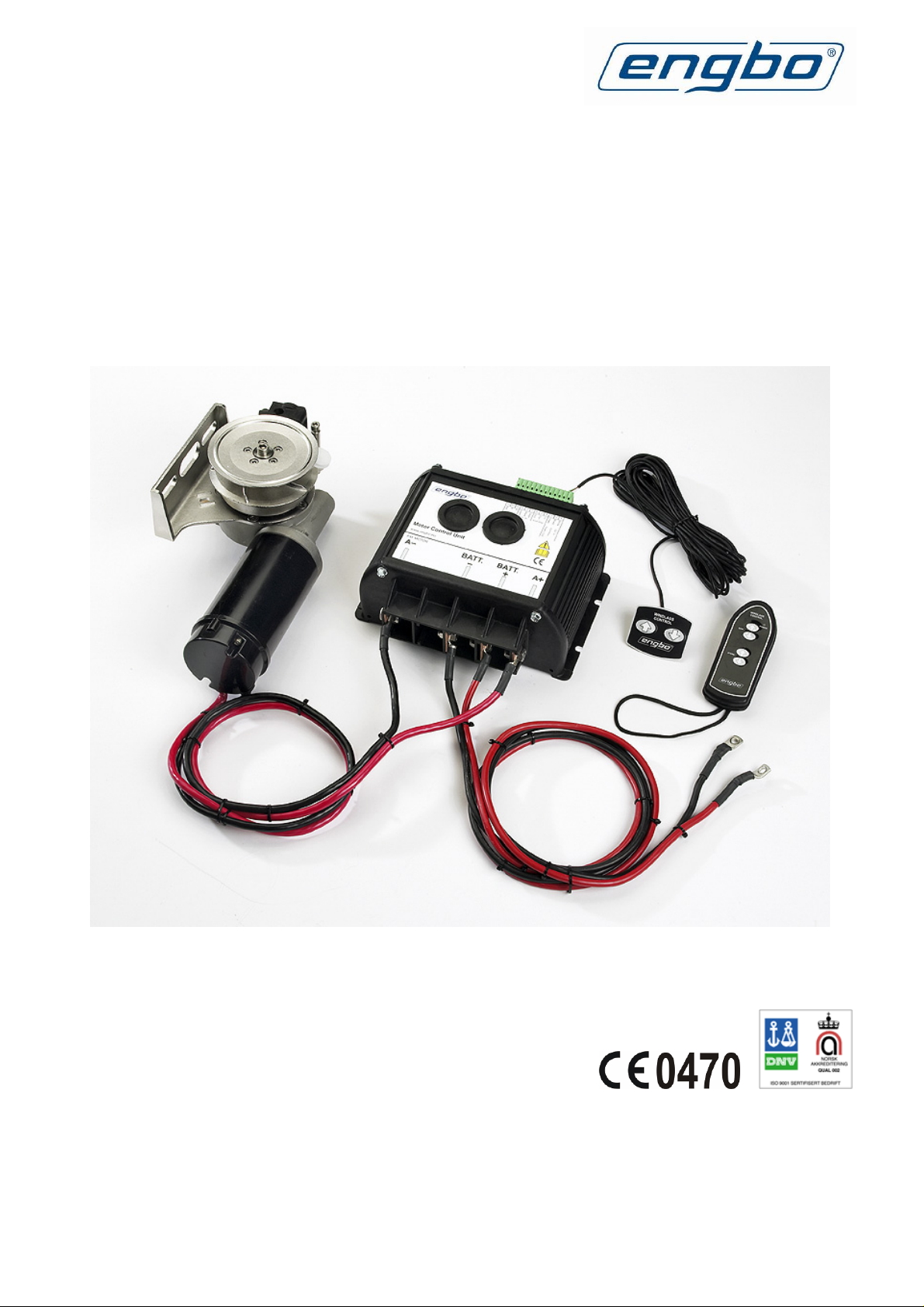
The picture shows a Midi 200 system.
(Wireless remote control and battery cables are optional.)
Rev: 2
FCC ID: R78-ECU-01
R78-RC-01
ENGBO AS – a company in the Engbo Group
OFFICE: Wirgenes vei 7, N-3159 Barkåker POSTAL ADDR.: P.O. Box 2288 Postterminalen, N-3103 Tønsberg
E-MAIL: support@engbo.no WEB: www.engbo.no TEL.: +47 33 00 31 50 FAX: +47 33 00 31 60

TABLE OF CONTENTS
INTRODUCTION............................................................................................................................. 3
Brief description of the winches ...................................................................................................................3
Dimensioned drawings............................................................................................................................................3
TECHNICAL DATA......................................................................................................................... 4
WIRING............................................................................................................................................. 5
Connection of switch panel......................................................................................................................................5
Connection of end stop sensor................................................................................................................................. 5
Connection of motor leads and battery ca bles........................................................................................................ 6
Battery connection...................................................................................................................................................6
Wiring diagram.............................................................................................................................................7
INSTALLATION INSTRUCTIONS ................................................................................................ 8
General....................................................................................................................................................................8
Use of anchor bracket ............................................................................................................................................. 8
Stern penetrations....................................................................................................................................................8
Fixed anchor bracket or hinged anchor bracket..................................................................................................... 8
Cover with rollers for hole ...................................................................................................................................... 8
INSTALLATION EXAMPLES ........................................................................................................ 9
OPERATING INSTRUCTIONS .................................................................................................... 10
General..................................................................................................................................................................10
Dropping anchor ................................................................................................................................................... 11
Hauling in....................................................................................................................................................11
Automatic end stop .....................................................................................................................................11
Forced operation .........................................................................................................................................11
Installation of end stop wires................................................................................................................................. 12
WIRELESS REMOTE CONTROL................................................................................................ 14
Operating instructions.................................................................................................................................14
Dropping anchor ................................................................................................................................................... 14
Hauling in..............................................................................................................................................................15
Forced operation...................................................................................................................................................15
Battery replacement ....................................................................................................................................15
Retrofit........................................................................................................................................................16
Coding the unit............................................................................................................................................17
MAINTENANCE ............................................................................................................................ 18
Winter storage.......................................................................................................................................................18
Adjustment of end stop device....................................................................................................................18
Adjustment of the rope roller guide....................................................................................................................... 18
TROUBLESHOOTING – MINI 100/MIDI 200............................................................................ 19
FCC Statements............................................................................................................................... 20
ENGBO AS – a company in the Engbo Group
OFFICE: Wirgenes vei 7, N-3159 Barkåker POSTAL ADDR.: P.O. Box 2288 Postterminalen, N-3103 Tønsberg
E-MAIL: support@engbo.no WEB: www.engbo.no TEL.: +47 33 00 31 50 FAX: +47 33 00 31 60
2
INTRODUCTION
Congratulations on your new winch and thank you for choosing an Engbo product. We
hope your winch will meet your expectations. Please note that this requires that the winch
be installed and used in accordance with this manual in an environment with the correct
conditions for proper operation. This includes the necessary battery capacity for the winch
motor as well as correct placement of winch, rope, anchor and anchor bracket.
Brief description of the winches
Engbo MINI 100 is designed for boats up to approximately 20 feet and Engbo MIDI 200
for boats between 20 to 25 feet. These winches are true free-fall winches and equipped
with a new power electronics that replaces the traditional contactor. The new electronics
have no open contacts and are very flexible as regards voltage. Engbo MINI 100 and
MIDI 200 are also equipped with new control electronics with an integrated radio
receiver for the wireless remote control as well as an integrated protection of the winch
motor and electronics.
The winches are supplied with control panel as standard. A wireless remote control with a
range of > 30 m under normal conditions can optionally be used.
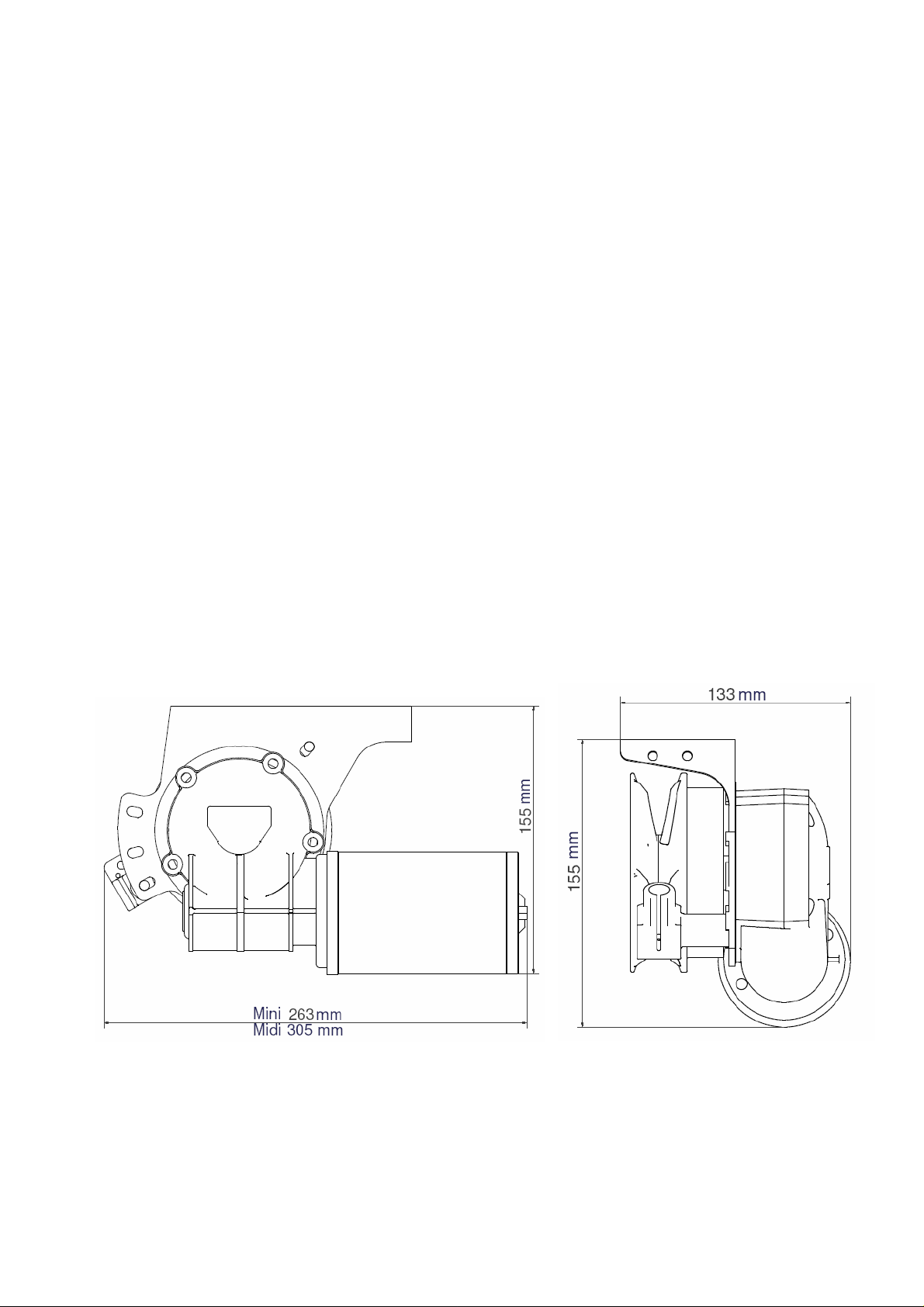
Dimensioned drawings
ENGBO AS – a company in the Engbo Group
OFFICE: Wirgenes vei 7, N-3159 Barkåker POSTAL ADDR.: P.O. Box 2288 Postterminalen, N-3103 Tønsberg
E-MAIL: support@engbo.no WEB: www.engbo.no TEL.: +47 33 00 31 50 FAX: +47 33 00 31 60
3

TECHNICAL DATA
Motor power nom.
Rope
Maximum pull
Haulage speed
Current draw
Standby current
consumtion
Recommended fuse
Recommended min.
battery capacity
Weight: Winch with
motor leads
Weight: Control
electronics
End stop function
Recommended
anchor
Recommended
vessel size
Installation
Standard equipment
Optional equipment
ENGBO – MINI 100 ENGBO – MIDI 200
12 V DC/350 W 12 V DC/600 W
Braided leaded rope: Dia 12 mm,
30 m
Weight:7,2 kg
Breaking load: 1200 daN
Up to 100 kg
(Electronic limit)
15-35 m/min
approx. 20 m/min with 20 kg load
10-150 A
approx. 50 A with 20 kg load
Braided lead rope diameter 12
mm, 30/50 m
Weight: 7.2 kg/12 kg
Breaking load: 1600 daN
Up to 200 kg
(Electronic limit)
15-30 m/min
approx. 20 m/min with 30 kg load
10-200 A
approx. 40 A with 30 kg load
‹ 0.3 A at 12 V ‹ 0.3 A at 12 V
100 A 150 A
12 V/75 Ah 12 V/75 Ah
5.5 kg 7.7 kg
2.3 kg 2.3 kg
No Yes
5-8 kg Bruce or plate 7.5-16 kg Bruce, plate or Engbo
Max. 6.0 m (20 feet) Max. 7.6 m (25 feet)
Vertical, hanging, forward or side
(may require additional bracket).
Winch, electronic module, control
panel and main switch.
Basic installation bolt set.
Vertical, hanging, forward or side
(may require additional bracket).
Winch with end stop device,
electronic module, control panel
and main switch.
Basic installation bolt set.
Lead rope
Anchor (several types available)
Anchor bracket (several types)
Shackles
Wireless remote control
Fuse and fuse holder
Installation bracket(s)
Battery cable
Lead rope
Anchor (several types available)
Anchor bracket (several types)
Shackles
Wireless remote control
Fuse and fuse holder
Installation bracket(s)
Battery cable
ENGBO AS – a company in the Engbo Group
OFFICE: Wirgenes vei 7, N-3159 Barkåker POSTAL ADDR.: P.O. Box 2288 Postterminalen, N-3103 Tønsberg
E-MAIL: support@engbo.no WEB: www.engbo.no TEL.: +47 33 00 31 50 FAX: +47 33 00 31 60
4
WIRING
The sticker on top of the electronics module also shows the wiring of the unit.
All wiring and connections must be done with the main switch turned off or the battery
disconnected.
Control panel for fixed installation.
Watertight (IP 68) control panel for installation
exposed to sea spray and sun. Designed to allow
installation directly on gently curved surfaces as
well (double-sided tape). The enclosed screws may
also be used.
An optional adapter plate (part no. 112-10015) can
be used for installation in existing 62 x 62 mm hole.
Several panels can be connected in parallel to the
same electronics unit.
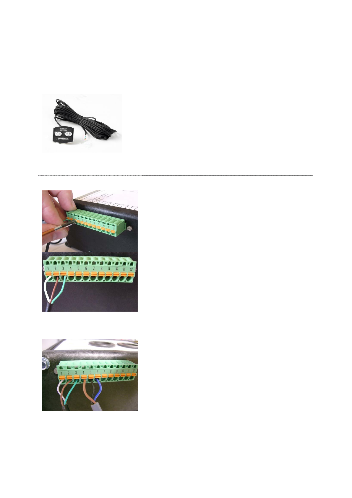
Connection of switch panel
One switch panel is supplied as standard with a
10m cable. The wires are cut and the insulation
stripped to the correct length and connected by
pushing the wires in while holding down the orange
button above the selected hole. Release the button
when the wire is in place. Check to make sure that
the insulation is not inside the terminal and that
there are no loose strands sticking out.
The wires must be connected as follows:
1: White
2: Brown
3: Green
If more than one panel is to be installed, connect
the wires in parallel to 1, 2 and 3 (2 is common 0 V)
(Spring-clamp terminal strips are used to avoid the
risk of the connections coming loose due to
vibration or temperature changes.)
Connection of end stop sensor
(Note: MIDI 200 ONLY)
The wires from the end stop sensor are connected
as described above.
The wires must be connected as follows:
4: Brown (BN) = +V
5: Black (BK) = Signal
6: Blue (BU) = Gnd
ENGBO AS – a company in the Engbo Group
OFFICE: Wirgenes vei 7, N-3159 Barkåker POSTAL ADDR.: P.O. Box 2288 Postterminalen, N-3103 Tønsberg
E-MAIL: support@engbo.no WEB: www.engbo.no TEL.: +47 33 00 31 50 FAX: +47 33 00 31 60
5
WARNING !!
!
!
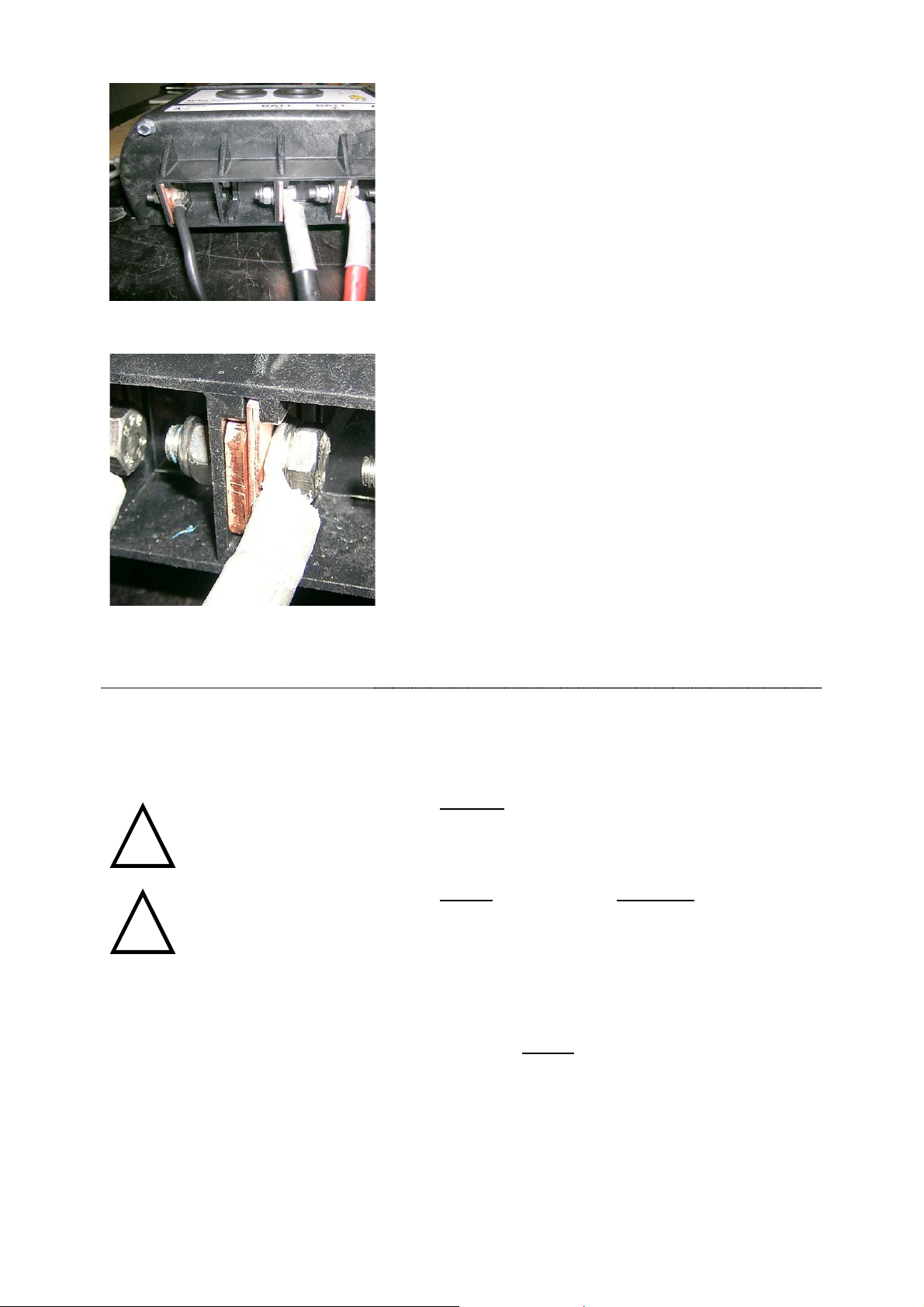
Connection of motor leads and battery
cables
The preferred method is to first fit the cables on the
unit before installing it standing against the
bulkhead with the power cables pointing downward.
The motor leads are supplied fitted on the motor.
Start by connecting the motor's black negative lead
to the left before the battery's black negative cable,
then the battery's positive cable and finally the
motor's positive lead. (Disassemble in opposite
order if necessary.)
The picture shows the correct connection and
orientation of bolts and cables (the lock nuts on the
left side).
(The cable terminals must be connected directly to
the copper rails without any washers, etc. in
between. Use a flat washer between the bolt head
and the top of the cable terminal and between the
plastic side of the end wall and lock nut.)
The M8 x 25 mm bolt is for the battery's positive
conductor.
Note the copper plate used as a spacer in the end
wall.
For normal distances from the battery to the
electronics module (< 4 m), use 25 mm
100 and 35 mm
2
for MIDI 200. If the distance is
longer, use the next size larger cable dimension.
2
for MINI
Battery connection
• INCORRECT BATTERY POLARITY WILL
PERMANENTLY DESTROY THE POWER
ELECTRONICS
BEFORE CONNECTING THE BATTERY - MAKE
•
SURE NO CABLES ARE SHORT-CIRCUITED OR
DAMAGED
• CHECK ALL POWER CABLES AND TERMINALS;
TIGHTEN UP IF NECESSARY
NEVER USE WASHERS BETWEEN CABLE
•
TERMINALS AND TERMINAL POINTS WITH
HEAVY CURRENTS.
The battery's positive cable must have a fuse as close to
the battery as possible and the main switch must be
installed in an accessible location before the electronics
unit.
Windlasses must
battery.
always be connected to the start
ENGBO AS – a company in the Engbo Group
OFFICE: Wirgenes vei 7, N-3159 Barkåker POSTAL ADDR.: P.O. Box 2288 Postterminalen, N-3103 Tønsberg
E-MAIL: support@engbo.no WEB: www.engbo.no TEL.: +47 33 00 31 50 FAX: +47 33 00 31 60
6
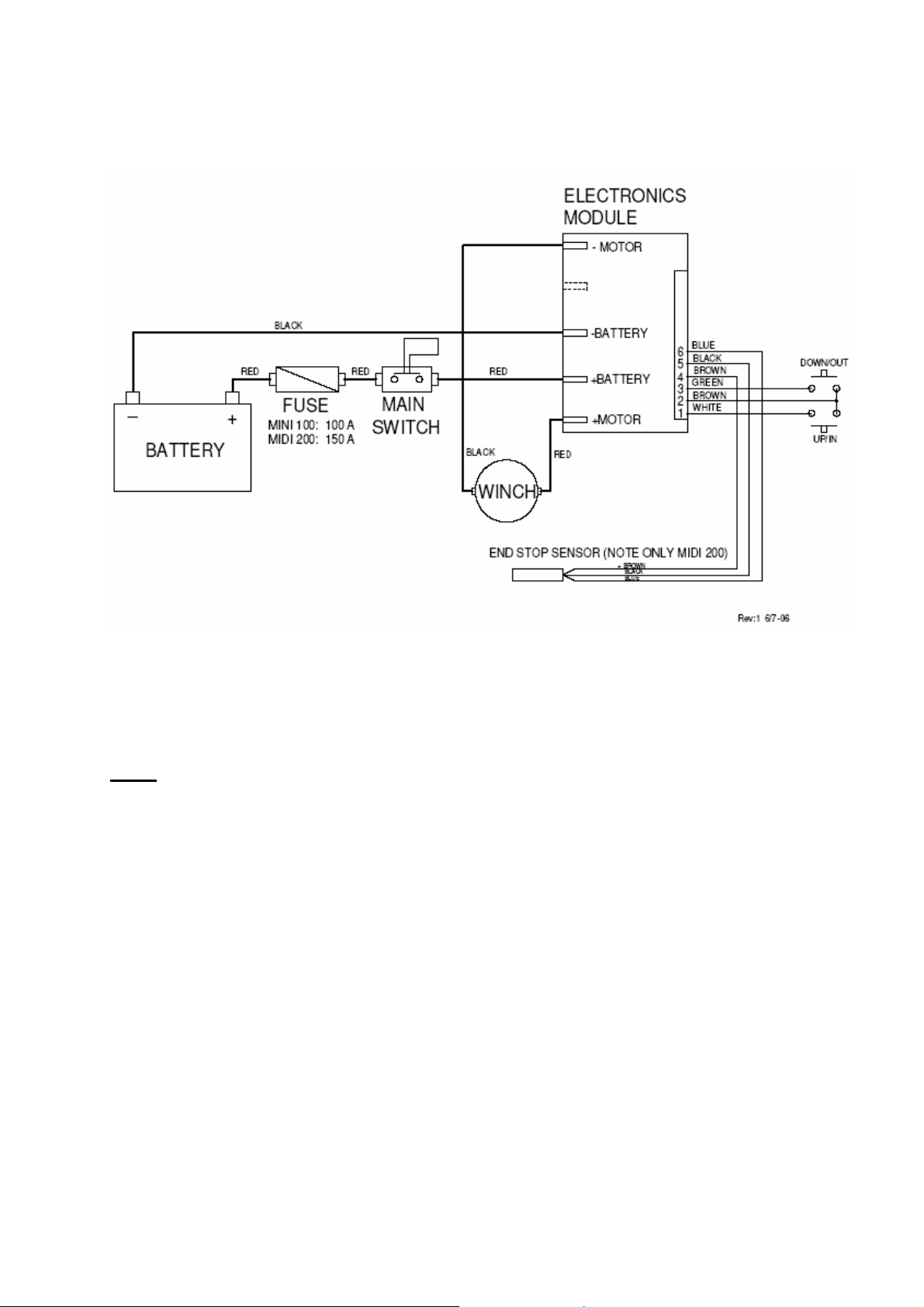
Wiring diagram
NOTE!
The winch must be connected to the boat's start battery and connected
after the boat's main switch.
ENGBO AS – a company in the Engbo Group
OFFICE: Wirgenes vei 7, N-3159 Barkåker POSTAL ADDR.: P.O. Box 2288 Postterminalen, N-3103 Tønsberg
E-MAIL: support@engbo.no WEB: www.engbo.no TEL.: +47 33 00 31 50 FAX: +47 33 00 31 60
7

INSTALLATION INSTRUCTIONS
General
Locate the winch as high as possible to allow plenty of room for rope below the winch.
The height from lower edge of the gypsy should be at least 40 cm above the bottom of the
rope locker or where the rope will be placed. This is to allow space for 50 metres of 12
mm Engbo braided anchor rope. If the height is less than 40 cm, make sure the rope does
not pile all the way up to the winch. If this is the case, use a shorter rope.
The winch should be installed far enough to the centre of the stern that the anchor does
not drag in the wave curving in right behind the boat.
Use of anchor bracket
The bracket for the rope must be installed with the sheaves outside the platform to ensure
the anchor/rope clears the platform.
Stern penetrations
Make sure the hole in the hull is located correctly based on the direction of the rope. To
avoid unnecessary wear and tear the rope should not touch the sides of the hole vertically
or horizontally, and the hole must be elliptical vertically to allow for rope movement on the
roller when winching.
Fixed anchor bracket or hinged anchor bracket
If the winch must be installed so low in relation to the swim platform that it will pull the
anchor forward/inward rather than upward/inward, it is preferable to use our hinged
anchor bracket (see catalogue).
Cover with rollers for hole
If it proves difficult to route the rope straight vertically from the gypsy to the anchor roller,
it may be beneficial to use a cover with rollers to allow for the rope angle.
NOTE! Remember to fasten the end of the rope to the boat.
ENGBO AS – a company in the Engbo Group
OFFICE: Wirgenes vei 7, N-3159 Barkåker POSTAL ADDR.: P.O. Box 2288 Postterminalen, N-3103 Tønsberg
E-MAIL: support@engbo.no WEB: www.engbo.no TEL.: +47 33 00 31 50 FAX: +47 33 00 31 60
8

INSTALLATION EXAMPLES
The pictures below show different installations
Mini 100 only
ENGBO AS – a company in the Engbo Group
OFFICE: Wirgenes vei 7, N-3159 Barkåker POSTAL ADDR.: P.O. Box 2288 Postterminalen, N-3103 Tønsberg
E-MAIL: support@engbo.no WEB: www.engbo.no TEL.: +47 33 00 31 50 FAX: +47 33 00 31 60
9

OPERATING INSTRUCTIONS
General
Read the entire operating instructions carefully before using the winch.
1. Please remember that heavy loads are involved. Therefore use common sense
when operating the winch and make sure that:
Fingers do not become entangled in rope, rollers or gypsy.
The rope is always monitored when hoisting the anchor.
Everyone on board is informed about how to operate the winch.
2. Always operate the winch from a location with full overview when hauling the
anchor. This is necessary in case the anchor hooks on something unexpected that
may damage the boat.
3. If the winch works hard when raising the anchor, release the button for a moment.
When the boat has started moving aft, start the winch again. This will ensure that
the winch will work less hard and draw less current.
4. Keep the anchor rope taut when winding long lengths of rope.
5. Should the anchor be stuck on the bottom, do as follows: Pay out some rope and
fasten it to a cleat in the boat. Use the boat to loosen the anchor. When the anchor
is loose, use the winch in the normal manner.
6. The winch can be operated for a maximum of 3 minutes with a normal load.
7.
Always secure the anchor to the boat with a safety rope when sailing. A snap
hook can be used to fasten it to an eye/shackle, for example. A safety rope is
enclosed.
8. Children must not operate the winch.
9. Careless use may result in unnecessary damage/injury.
10. Always make sure there is sufficient battery capasity when using the winch.
Always keep the engine running while using the winch.
11. The winch has an electronic overload protection. If necessary, let the winch cool
down for approximately 15 min and try again. In an emergency, this protection may
be overridden by turning the winch off and back on again. (Overrides are saved by
the processor.)
12. Engbo AS is not responsible for injury or damage as a result of the use of the
winch.
NOTE! ALWAYS KEEP THE ENGINE RUNNING WHEN USING THE WINCH AND ALWAYS
TURN OFF THE POWER TO THE WINCH WHEN NOT IN USE.
ENGBO AS – a company in the Engbo Group
OFFICE: Wirgenes vei 7, N-3159 Barkåker POSTAL ADDR.: P.O. Box 2288 Postterminalen, N-3103 Tønsberg
E-MAIL: support@engbo.no WEB: www.engbo.no TEL.: +47 33 00 31 50 FAX: +47 33 00 31 60
10

Dropping anchor
Engbo MINI 100 and MIDI 200 has a true free-fall anchor drop function. One press of the
button and the anchor drops freely to the bottom.
The anchor should be dropped a distance from where the boat will be located
corresponding to 3-5 times the water depth.
When the anchor winch has been turned off with the main
switch, always press the "DOWN/OUT" button first (marked
with an arrow pointing downward). This button must be held
in for at least 1 second to drop the anchor.
The winch will then pay out for 3 seconds to ensure correct
free-fall function. (This time period is 3 seconds regardless
of how long the button is pressed.)
Hauling in
When the anchor is out, haul in the anchor by pressing the
"UP/IN" button (marked with an arrow pointing upwards).
The winch will haul in the rope for as long as the button is
held in.
The winch always starts with 3 seconds at low speed before
increasing to full speed.
The winch can also be operated at low speed by pushing
and releasing the "IN" button several times.
Automatic end stop
Note! MIDI 200 ONLY
Assumes correctly positioned end stop wires on the anchor
rope.
When the first end stop wire is sensed by the end stop
sensor when hauling in the anchor, the winch will stop. The
button must then be released and pushed once more. The
winch will then operate at low speed until the second end
stop is sensed by the sensor. The winch will then stop
completely.
Forced operation
NOTE! MIDI 200 ONLY
If the anchor needs to be lifted a little further after end
stop 2, this can be done by holding down the "IN"
button for more than 10 seconds. The winch will then
operate at extra low speed for as long as the button is
held down.
NOTE! This operation must only be carried out
under very controlled circumstances to prevent
damage.
NOTE! ALWAYS KEEP THE ENGINE RUNNING WHEN USING THE WINCH AND
ALWAYS TURN OFF THE CURRENT TO THE WINCH WHEN NOT IN USE.
ENGBO AS – a company in the Engbo Group
OFFICE: Wirgenes vei 7, N-3159 Barkåker POSTAL ADDR.: P.O. Box 2288 Postterminalen, N-3103 Tønsberg
E-MAIL: support@engbo.no WEB: www.engbo.no TEL.: +47 33 00 31 50 FAX: +47 33 00 31 60
11

Installation of end stop wires
NOTE! MIDI 200 ONLY
Integrated in the rope rejector is an inductive sensor that signals end stop when the
anchor has been lifted all the way up. To activate the sensor, two brass wires (included)
are fitted on the rope (see procedure below).
The outer diameter of the brass wire winding must be similar to the outer diameter of the
rope, or as close as possible. This is necessary in order for the inductive sensor to be
able to detect the wire.
To locate the brass wires correctly on the rope, haul in the anchor until the thumble is 2550 cm below the rope roller (operate at slow speed for the final length), and mark the rope
with a marker pen at the inductive sensor. The anchor is then reeled in at low speed to
the desired final resting position. Mark the rope once more at the sensor. These marked
positions are where the wires shall be fastened.
These wires will be exposed to wear by the gypsy, especially during heavy loads, and
must therefore be inspected regularly. Replace damaged wires as needed.
ENGBO AS – a company in the Engbo Group
OFFICE: Wirgenes vei 7, N-3159 Barkåker POSTAL ADDR.: P.O. Box 2288 Postterminalen, N-3103 Tønsberg
E-MAIL: support@engbo.no WEB: www.engbo.no TEL.: +47 33 00 31 50 FAX: +47 33 00 31 60
Cut approximately 25 cm of brass wire for each
signal location. (The length of the supplied brass
wire is approximately 1m.)
The rope and installation is shown with the
anchor at the bottom right.
Use an awl to make a hole for the wire where
the rope is marked.
Bend 6-7 mm at 90 degrees and push this end
into the hole.
It may be beneficial to use a pair of pliers to
force the wire into the rope and to keep it in
place initially while winding the wire around the
rope.
12

Wind the wire four complete turns around the
rope.
After four turns and on the opposite side of
where you started, "sew" the wire into the rope.
Use the awl to carefully make a hole for the wire,
push the wire through and tighten.
Repeat the sewing operation once more.
Then cut the wire and bend the end at 90
degrees towards the middle of the rope.
Force the end into the rope with the pliers.
A fitted end wire should look like this with close
windings and the ends secured inside the rope.
ENGBO AS – a company in the Engbo Group
OFFICE: Wirgenes vei 7, N-3159 Barkåker POSTAL ADDR.: P.O. Box 2288 Postterminalen, N-3103 Tønsberg
E-MAIL: support@engbo.no WEB: www.engbo.no TEL.: +47 33 00 31 50 FAX: +47 33 00 31 60
13

WIRELESS REMOTE CONTROL
Floating, splash-proof, hand-held remote control unit. The operating range is > 30 m
under normal conditions. The Engbo remote control is a high quality, narrow band unit
with two-way communication with the electronics unit. Each unit has a unique code.
It uses three standard AAA (LR03) batteries (included).
It has anti-slip strips on the back.
Fits in a standard mobile phone holder.
Hand cord is included as standard (easily removed).
The battery lifetime is > 2 seasons based on normal use.
One remote control can be used to operate two winches. The remote control units are
normally supplied programmed for the enclosed electronics unit. Both button pairs are
then programmed.
Operating instructions
The remote control is battery-operated. To ensure longer
lifetime, it will automatically go to “sleep” mode five
minutes after the last button was pushed. Deactivation is
signalled with two short sound bursts and blinks in the
"POWER" indicator. The remote control is activated by
holding down any button for 1.5 seconds. Activation is
indicated by a steady green light in the "POWER"
indicator and a short sound. All subsequent use of
buttons is shown on the associated indicator above the
button and a short sound.
The "POWER" indicator is also used to indicate low
voltage at the electronics unit. This is indicated by an
orange light. If the winch is overloaded and requires time
to cool down, this will also be indicated by an orange
light. The indicator will be red in case of system faults
and slowly blink red together with short sounds if the
remote is unable to communicate with the electronics
unit. These error messages are shown when buttons are
pushed.
Dropping anchor
When the remote control has been activated, the anchor
can be dropped by pressing the "DOWN/OUT" button
(marked with downwards arrow) again. This button must
be held in for at least 1 second to drop the anchor.
The winch will then pay out for 3 seconds to ensure
correct free-fall function. (This time period is 3 seconds
regardless of how long the button is pressed.)
ENGBO AS – a company in the Engbo Group
OFFICE: Wirgenes vei 7, N-3159 Barkåker POSTAL ADDR.: P.O. Box 2288 Postterminalen, N-3103 Tønsberg
E-MAIL: support@engbo.no WEB: www.engbo.no TEL.: +47 33 00 31 50 FAX: +47 33 00 31 60
14

Hauling in
When the anchor has been dropped, start weighing
anchor by pressing once on the "UP/IN" button (marked
with upwards arrow). If the remote control has been
deactivated (more than five minutes elapsed since the
last button activation), it will first be turned on and then
immediately start hauling in the anchor. The winch
always starts with 3 seconds at low speed before
increasing to full speed.
The winch can thereby also operate at low speed by
pushing and releasing the "IN" button several times.
Forced operation
NOTE! MIDI 200 ONLY
If the anchor needs to be lifted a little further after end
stop 2, this can be done by holding down the "IN" button
for more than 10 seconds. The winch will then operate at
low speed for as long as the button is held down.
This is indicated on the remote control by a green light
slowly blinking above the "IN" button and rapid, brief
sound bursts.
NOTE! This operation must only be carried out under
very controlled circumstances to prevent damage.
Battery replacement
The remote control uses three regular AAA/LR03
alkaline batteries. The battery lifetime is more than two
seasons under normal use.
When replacing batteries, open the unit by unscrewing
all five screws.
NOTE! The screws are of different lengths and have
O-rings under the screw heads.
Replace the batteries and make sure all point the same
way with the + up and the – downwards towards the
edge as illustrated.
Reassemble the back cover and carefully screw the
parts together until the housing gasket is
lightly
compressed. The impermeability of this unit depends
on intact O-rings and intact gasket with the right
compression.
NOTE! To ensure a long lifetime, this remote
control has acid-proof machine screws and screw
inserts in the housing. The screws may penetrate
the housing if screwed carelessly or too much
force is used.
(Not covered by the warranty.)
ENGBO AS – a company in the Engbo Group
OFFICE: Wirgenes vei 7, N-3159 Barkåker POSTAL ADDR.: P.O. Box 2288 Postterminalen, N-3103 Tønsberg
E-MAIL: support@engbo.no WEB: www.engbo.no TEL.: +47 33 00 31 50 FAX: +47 33 00 31 60
15

Retrofit
If the remote control is purchased after the electronics unit, the electronics unit must be
fitted with an antenna. The remote control and electronics unit must also be coded/taught
electronically to communicate with each other.
Remove the left rubber cover (the one closest to
the Engbo logo). Then push the antenna through
the cover (on one side).
While holding down the antenna connector
handle, push the antenna all the way down into
the bottom of the clamp. Release the handle and
the antenna is fixed in place.
Replace the rubber cover. Start by pushing the
rubber cover in by the antenna and continue
around the edge until the cover is fixed in place.
Make sure not to twist the cover with the
antenna.
(The remote control will function over short
distances also without the antenna.)
ENGBO AS – a company in the Engbo Group
OFFICE: Wirgenes vei 7, N-3159 Barkåker POSTAL ADDR.: P.O. Box 2288 Postterminalen, N-3103 Tønsberg
E-MAIL: support@engbo.no WEB: www.engbo.no TEL.: +47 33 00 31 50 FAX: +47 33 00 31 60
16

Coding the unit
The remote control (transmitter) can be
coded/taught electronically to communicate with
the selected
two). The electronics unit and remote control must
be close to each other and set to code/teaching
mode at the same time as described below:
1.
The remote control unit is set in
code/teaching mode by holding down both
buttons in the pair of buttons to be used for
10 seconds (see Image A).
control indicates that it is in the
code/teaching mode by the "POWER"
indicator starting to slowly blink green and
a short sound. The remote control will
Image A
remain in this mode until correctly coded or
until the same two buttons are pushed
again. If not, it will automatically turn off
after five minutes. When exiting from this
mode, there will be a short sound burst and
the "POWER" indicator will no longer be lit.
2. Hold down both switches on the
permanently installed switch panel while
turning on the main switch. Then release
the switches (see Images B and C).
electronics unit will now be in code mode.
(This can also be done by temporarily
connecting between 1, 2 and 3 on the
electronics unit.)
now remain in the programming mode for
only 10 seconds, and then switch back to
the normal mode again.
3. Press one of the two switches on the
Image B
remote control that controls either the bow
or aft winch. This must be done within the
10 seconds that the electronics unit is in
the code mode. Correct coding is confirmed
with a short sound signal from the remote
control.
4. The remote control is now coded and ready
for use.
Image C
This coding/teaching can be done an unlimited
number of times.
electronics unit(s) (receiver), (max.
The electronics unit will
The remote
The
ENGBO AS – a company in the Engbo Group
OFFICE: Wirgenes vei 7, N-3159 Barkåker POSTAL ADDR.: P.O. Box 2288 Postterminalen, N-3103 Tønsberg
E-MAIL: support@engbo.no WEB: www.engbo.no TEL.: +47 33 00 31 50 FAX: +47 33 00 31 60
17

MAINTENANCE
Winter storage
• Before winter storage, the winch and all electrical terminals and connections must
be coated with a moisture proofing spray.
• Make sure the winch is protected against snow during winter storage.
• Do not cover up the winch to avoid condensation during winter storage.
• Remove the rope before winter storage. Soak it in mild soapy water overnight to
remove salt deposit and dirt. This will ensure that the rope remains supple for
many years and allows for checking and possible replacement of the end stop
wires.
If relevant, clean the rope locker on the inside and remove any seaweed, mud, etc.
Adjustment of end stop device
NOTE! MIDI 200 ONLY
The device will normally be adjusted and
extend approximately 1 mm from the
holder. If adjustment is necessary, loosen
the screw holding the inductive sensor.
Move the sensor to the correct position,
but make sure that the rope will not be
caught in it. Retighten the screw.
(Previous model shown. Latest models:
Install sensor onto end wall.)
Adjustment of the rope roller guide
The guide will normally be adjusted for 12
mm rope.
The guide must be at a straight angle in
relation to the rope with a gentle pressure
against the rope when the rope is located
in its normal position in the gypsy.
If adjustment is needed, loosen the screw
under the bracket to adjust the pressure
against the rope. Loosen the screw on
top of the holder to adjust the angle and
distance.
ENGBO AS – a company in the Engbo Group
OFFICE: Wirgenes vei 7, N-3159 Barkåker POSTAL ADDR.: P.O. Box 2288 Postterminalen, N-3103 Tønsberg
E-MAIL: support@engbo.no WEB: www.engbo.no TEL.: +47 33 00 31 50 FAX: +47 33 00 31 60
18

TROUBLESHOOTING – MINI 100/MIDI 200
(For wiring, see diagram under the section "Wiring".)
Symptom: Action and please note the
following:
1 The winch is totally
"dead". Nothing
works.
2 The winch will not
drop the anchor,
and only reels in for
3 s.
3 The winch does not
work or pulls very
poorly.
4 If the winch still
does not function.
5 If the end stop does
not function:
(MIDI 200 ONLY)
or Engbo AS, Tønsberg. Tel.: +47 33003150, Fax: +47 33003160, E-mail: support@engbo.no
ENGBO AS – a company in the Engbo Group
OFFICE: Wirgenes vei 7, N-3159 Barkåker POSTAL ADDR.: P.O. Box 2288 Postterminalen, N-3103 Tønsberg
E-MAIL: support@engbo.no WEB: www.engbo.no TEL.: +47 33 00 31 50 FAX: +47 33 00 31 60
NOTE! The main current switch
must be turned off when
connecting and disconnecting
cables and performing
mechanical work.
Check that:
- the main switch is turned on,
- the fuse is intact
- all terminals have good contact
- all connections are according
to diagram in the manual
- there is sufficient power to the
winch motor.
(See Item 3)
Check that:
- connections to 1, 2 and 3 are according to diagram. By
switching 1 and 3, the winch should function correctly.
IMPORTANT!
Based on previous
experience, this is the most
common problem.
Look for main current faults:
Measure the battery voltage at
the input to the winch while
operating the winch.
Disconnect cables to 1, 2 and 3.
--------
Strip the insulation on the ends
of a loose cable (approx. 10 cm)
and establish contact between
these points:
Cable between 2 and 3
Cable between 1 and 2
Check that:
- connections to 4, 5 and 6 are
according to diagram.
- the power to sensor (between
4 and 6) is more than 10 V DC
- end stop wires are in place.
If the winch still does not function normally after this procedure,
the fault is located in the winch itself. Contact the nearest dealer,
Action results in: Result
The voltage must be
minimum 10.5 V when
operating the winch to
ensure normal motor
function.
Functions that normally are
controlled from the switch
panel are disconnected to
allow forced operation of the
winch directly from the
electronics unit.
--------
The winch is released and
the anchor dropped.
Winch reels in.
The indicator lamp on the
sensor must light up when
the brass ring on the rope is
by the sensor.
(Can also be tested using a
screwdriver, or similar, by
the sensor.)
If the voltage is below 10.5 V, the
reason must be determined.
Check all connections, e.g. main
switch, fuse, battery terminals,
battery voltage and the battery's
general condition.
If the voltage is higher than
10.5 V but the motor will still not
run, the reason may be that
extended use/overloading of the
winch has resulted in the
electronic protection shutting off
the motor.
Wait 20 min. to let it cool down
and try again.
The switch panel is disconnected.
--------
If the winch functions normally
using this procedure, the fault is
located in a cable to the switch
panel, or the switch panel itself,
and must be replaced.
If the voltage is OK and the lamp
does not light, the sensor must be
replaced.
19

FCC Statements
This device complies with Part 15 of the FCC Rules. Operation is subject to the following
two conditions: (1) this device may not cause harmful interference, and (2) this device
must accept any interference received, including interference that may cause undisired
operation.
Changes or modifications to the equipment not expressly approved by the party
responsible for compliance could void the user’s authority to operate the equipment.
NOTE: This equipment has been tested and found to comply with the limits for a Class
B digital device, pursuant to Part 15 of the FCC Rules. These limits are designed to
provide reasonable protection against harmful interference in a residential installation.
This equipment generates, uses and can radiate radio frequency energy and, if not
installed and used in accordance with the instructions, may cause harmful interference
to radio communications. However, there is no guarantee that interference will not occur
in a particular installation.
If this equipment does cause harmful interference to radio or television reception, which
can be determined by turning the equipment off and on, the user is encouraged to try to
correct the interference by one or more of the following measures:
-- Reorient or relocate the receiving antenna.
-- Increase the separation between the equipment and receiver.
-- Connect the equipment into an outlet on a circuit different
from that to which the receiver is connected.
-- Consult the dealer or an experienced radio/TV technician for help.
ENGBO AS – a company in the Engbo Group
OFFICE: Wirgenes vei 7, N-3159 Barkåker POSTAL ADDR.: P.O. Box 2288 Postterminalen, N-3103 Tønsberg
E-MAIL: support@engbo.no WEB: www.engbo.no TEL.: +47 33 00 31 50 FAX: +47 33 00 31 60
20


 Loading...