

EngA ENGINEERED AIR HE Series, ENGINEERED AIR DE Series, ENGINEERED AIR RE Series Installation, Operation And Maintenance Manual
Page 1

A
UNIT MODEL NO. ___________________
UNIT SERIAL NO. ___________________
SERVICED BY: _____________________
TEL. NO: __________________________
CANADIAN
HEAD OFFICE
AND FACTORY
USA
HEAD OFFICE
AND FACTORY
CANADIAN
EASTERN FACTORY
1401 HASTINGS CRES. SE
CALGARY, ALBERTA
T2G 4C8
Ph: (403) 287-2590
Fx: 888-364-2727
Parts:
32050 W. 83rd STREET
DESOTO, KANSAS
66018
Ph: (913) 583-3181
Fx: (913) 583-1406
Parts:
1175 TWINNEY DRIVE
NEWMARKET, ONTARIO
L3Y 5V7
Ph: (905) 898-1114
Fx: (905) 898-7244
Parts:
SALES OFFICES ACROSS CANADA AND USA
Retain instructions with unit and maintain in a legible condition.
Please give model number and serial number when contacting
factory for information and/or parts.
INSTALLATION, OPERATION
AND MAINTENANCE MANUAL
FOR
HE, DE & RE SERIES
DIRECT FIRED HEATING UNITS
INDOOR AND OUTDOOR MODELS
IOM-26 Oct 12 R4
www.engineeredair.com
Page 2

A HE, DE & RE MANUAL
TABLE OF CONTENTS
YOU HAVE RESPONSIBILITIES TOO ........................................................................................................................................ 3
INTRODUCTION ............................................................................................................................................................................. 3
SAFETY PRECAUTIONS .............................................................................................................................................................. 3
WARRANTY ..................................................................................................................................................................................... 5
PARTS .............................................................................................................................................................................................. 6
RECEIVING ...................................................................................................................................................................................... 6
TEMPORARY STORAGE .............................................................................................................................................................. 6
INSTALLATION ................................................................................................................................................................ 7
CODES ............................................................................................................................................................................................. 7
LIFTING ............................................................................................................................................................................................ 9
MOUNTING ...................................................................................................................................................................................... 9
SHIPPING MATERIALS ................................................................................................................................................................10
ASSEMBLY .....................................................................................................................................................................................11
PIPING, ELECTRICAL OR CONTROL SERVICE CONNECTIONS ......................................................................................12
NATURAL GAS AND PROPANE INSTALLATION: ..................................................................................................................12
GAS LINE TESTING (EXTERNAL TO THE UNIT) ...................................................................................................................12
NON RECIRCULATING INSTALLATION REQUIREMENTS ..................................................................................................13
INLET DUCTING ............................................................................................................................................................................13
FIELD INSTALLED DAMPERS ....................................................................................................................................................14
DE PROCESS HEATER INSTALLATION REQUIREMENTS .................................................................................................15
EXHAUST FAN / RELIEF AIR PROVISIONS ............................................................................................................................16
LOW LIMIT FREEZE PROTECTION ..........................................................................................................................................16
ELECTRICAL INSTALLATION .....................................................................................................................................................16
Recommended 24V Field Wiring Size: ........................................................................................................................... 17
DUCT MOUNTED TE-6000-EA3 TEMPERATURE SENSOR ................................................................................................18
COIL CONNECTIONS ...................................................................................................................................................................18
DRAIN TRAPS ................................................................................................................................................................................19
FLUSHING AND DEGREASING OF WATER AND GLYCOL COILS ....................................................................................19
HEAT TRANSFER FLUIDS ..........................................................................................................................................................20
BEFORE START-UP ...................................................................................................................................................... 20
START-UP CHECK LIST ................................................................................................................................................ 20
OPERATION ................................................................................................ ............................................... 22
SAFETY SHUTOFF VALVE LEAK TEST: ..................................................................................................................................23
OPERATIONAL CHECK ...............................................................................................................................................................24
CONTROL SETTINGS ..................................................................................................................................................................25
MAINTENANCE .............................................................................................................................................................. 26
ELECTRICAL ..................................................................................................................................................................................26
BELT ADJUSTMENT .....................................................................................................................................................................27
SET SCREWS ................................................................................................................................................................................27
BEARING SETSCREW TORQUES ............................................................................................................................................28
LUBRICATION OF FAN BEARINGS ...........................................................................................................................................28
LUBRICATION OF DODGE FAN BEARINGS ...........................................................................................................................29
MOTOR LUBRICATION ................................................................................................................................................................31
GAS MANIFOLD.............................................................................................................................................................................31
BURNERS .......................................................................................................................................................................................32
FILTERS ..........................................................................................................................................................................................32
CONTROLS ....................................................................................................................................................................................33
CONTROL ENCLOSURE VENTILATION ..................................................................................................................................33
OUTDOOR AIR INTAKES, MIXING SECTIONS AND DAMPERS.........................................................................................33
COILS ...............................................................................................................................................................................................33
ULTRAVIOLET SCANNERS ........................................................................................................................................................33
© Airtex Manufacturing Partnership. All rights reserved.
IOM-26 2 of 33 Oct 12 R4
Page 3
A HE, DE & RE MANUAL
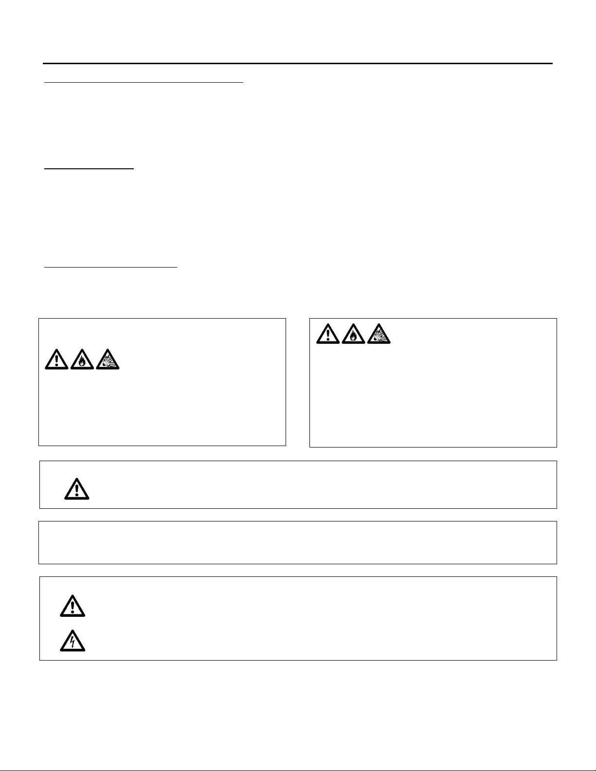
FOR YOUR SAFETY
The use and storage of gasoline or other flammable vapors and liquids in
open containers in the vicinity of this appliance is hazardous.
Warning:
This unit is connected to high voltages. Electrical shock or death could occur
if instructions are not followed. This equipment contains moving parts that can
start unexpectedly. Injury or death could occur if instructions are not
followed. All work should be performed by a qualified technician. Always
disconnect and lock out power before servicing. DO NOT bypass any interlock
or safety switches under any circumstances.
YOU HAVE RESPONSIBILITIES TOO
This installation, operation and maintenance manual can not cover every possibility, situation or
eventuality. Regular service, cleaning and maintaining the equipment is necessary. If you are not capable
of performing these tasks, hire a qualified service specialist. Failure to perform these duties can cause
property damage and/or harm to the building occupants and will void the manufacturers’ warranty.
INTRODUCTION
Engineered Air units are high quality products designed and manufactured to provide many years of
trouble-free operation. We recommend that this manual be read thoroughly to ensure proper installation,
efficient operation and proper maintenance of this equipment. The submittal record is considered to be
part of the Installation, Operation and Maintenance Manual. Please report any omissions to the national
service manager.
SAFETY PRECAUTIONS
Read, understand and follow the complete manual before beginning the installation, including all safety
precautions and warnings.
FOR YOUR SAFETY
WARNING:
If you smell gas:
1 Open windows.
2 Don't touch electrical switches.
3 Extinguish any open flame.
4 Immediately call your gas supplier.
FOR YOUR SAFETY
The use and storage of gasoline or other flammable vapors and liquids in open containers
in the vicinity of this appliance is hazardous.
Improper installation, adjustment,
alteration, service or maintenance can
cause property damage, injury or death.
Read the installation, operating and
maintenance instructions thoroughly
before installing or servicing this
equipment.
IOM-26 3 of 33 Oct 12 R4
Page 4
A HE, DE & RE MANUAL
Warning:
Pool, laundry and common cleaning products often contain fluorine or
chlorine compounds. When these chemicals pass through the heater,
they can form strong acids. The acid can eat through the heat
exchanger wall, causing serious damage and presenting a possible
threat of flue gas spillage into the building.
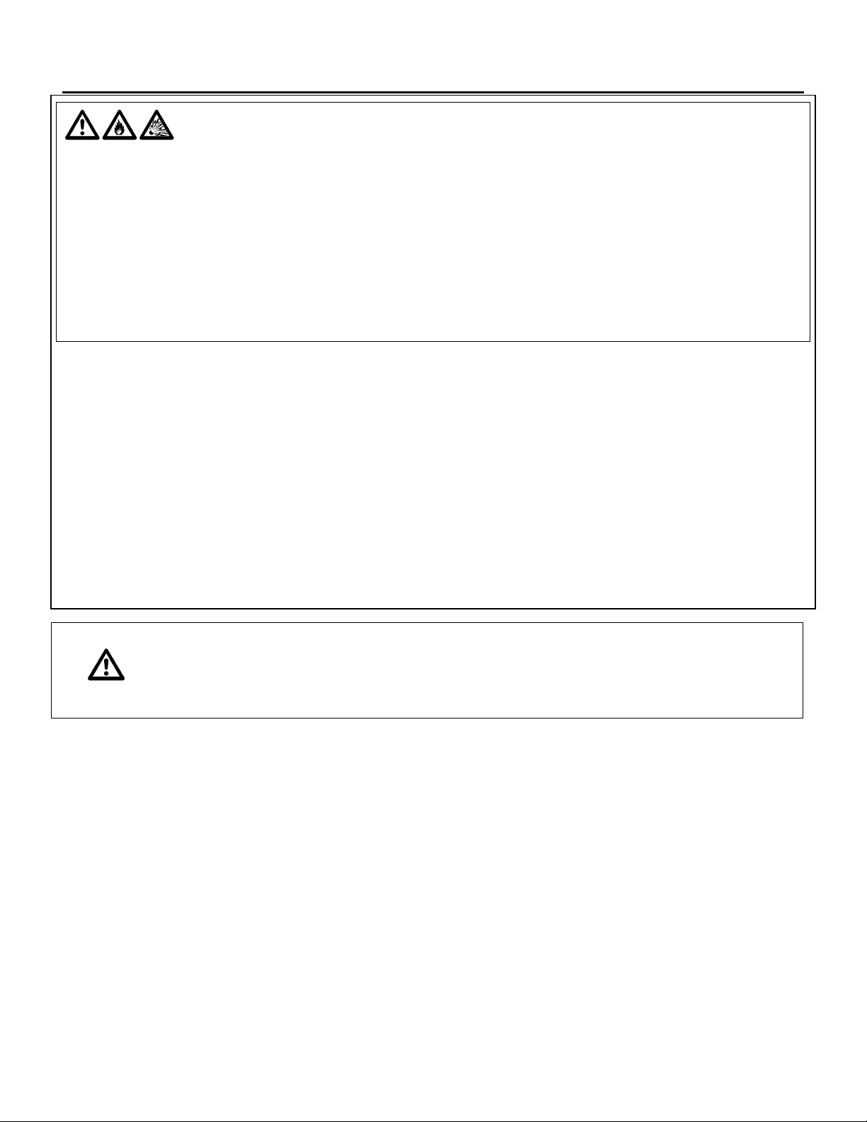
WARNING:
FIRE OR EXPLOSION HAZARD
Failure to follow safety warnings exactly could result in serious injury, death or property
damage.
Be sure to read and understand the installation, operation and service instructions in this
manual.
Improper installation, adjustment, alteration, service or maintenance can cause serious
injury, death or property damage.
— Do not store or use gasoline or other flammable vapors and liquids in the vicinity of this
or any other appliance.
— WHAT TO DO IF YOU SMELL GAS
Do not try to light any appliance.
Do not touch any electrical switch; do not use any phone in your building.
Leave the building immediately.
Immediately call your gas supplier from a phone remote from the building. Follow
the gas supplier’s instructions.
If you cannot reach your gas supplier, call the fire department.
— Installation and service must be performed by a qualified installer, service agency or the
gas supplier.
IOM-26 4 of 33 Oct 12 R4
Page 5

A HE, DE & RE MANUAL
WARRANTY
LIMITED WARRANTY ENGINEERED AIR will furnish without charge, F.O.B. factory, freight collect,
replacement parts for, or repairs to products covered herein which prove defective in material or
workmanship under normal and proper use for a period of twelve (12) months from the initial start-up or
eighteen (18) months from the date of shipment, whichever expires sooner, provided the customer gives
ENGINEERED AIR written notice of such defects within such time periods and provided that inspection by
ENGINEERED AIR establishes the validity of the claim and all pertinent invoices have been paid in full.
The repairs or replacements will be made only when the complete product(s) or part(s) claimed to be
defective are returned to ENGINEERED AIR or a depot designated by ENGINEERED AIR, transportation
charges prepaid. Repairs or replacements as provided for by this paragraph shall constitute fulfillment of
all ENGINEERED AIR's obligations with respect to this warranty. The refrigerant charge is not included in
any part of this warranty. This warranty does not apply to any products or parts thereof that have been
subject to accident, misuse or unauthorized alterations, or where ENGINEERED AIR's installation and
service requirements have not been met.
The foregoing warranty is in lieu of all other warranties, express or implied. ENGINEERED AIR specifically
disclaims any implied warranty of merchantability and/or fitness for purpose. Under no circumstances shall
ENGINEERED AIR be liable to, nor be required to indemnify, Buyer or any third parties for any claims,
losses, labour, expenses or damages (including special, indirect, incidental, or consequential damages) of
any kind, resulting from the performance (or lack thereof) of this Agreement or the use of, or inability to use
the goods sold hereunder, including, but not limited to, damages for delay, temporary heating/cooling
costs, loss of goodwill, loss of profits or loss of use. Furthermore, the parties agree that the Buyer's sole
remedy under this Agreement shall be limited to the limited warranty set forth in the preceding paragraph
relating to the repair or replacement of any defective goods. Under no circumstances shall any claim or
award against ENGINEERED AIR exceed the original contract price whether awarded through arbitration,
litigation or otherwise.
ENGINEERED AIR Warranty is void if:
1. The unit is not installed in accordance with this manual.
2. The start-up and operation of the unit is not performed in accordance with this manual.
3. The unit is operated in an atmosphere containing corrosive substances.
4. The unit is allowed to operate during building construction.
5. The unit is allowed to operate in atmospheres where chlorine or chlorine compounds are present or
which contain any contaminant (silicone, aluminum oxide etc.) that adheres to the spark ignition
flame sensing probe.
IOM-26 5 of 33 Oct 12 R4
Page 6
A HE, DE & RE MANUAL
Warning:
Any replacement part must be of equivalent listing or certification and be
functionally equivalent. The replacement part must meet the original’s
specification in terms of functionality including certifications, timing, input
and output range, accuracy and operation.
Failure to replace parts or components with equivalent parts can cause
property damage, injury or death.
PARTS
1. Motors:
Motor manufacturers have service centers that will repair or replace motors as required.
2. Parts Other Than Motors:
Contact the nearest Engineered Air sales office or factory. Be sure to include Model Number,
Serial Number, date of installation and nature of failure along with the description of the parts
required. Some parts may not be stocked items that must be made or ordered.
RECEIVING
Refer to the back of the packing slip for receiving unit instructions.
On receipt of the unit, check for damage. Inspect protective covers for punctures or other signs that there
may be internal damage. Remove protective covers and check for internal damage. Replace covers if the
unit is not being assembled or installed at this time. Open access doors and check for internal damage.
Close access doors when the inspection is complete.
All units are pre-tested at the factory immediately prior to shipping and are ensured to be in good operating
condition at that time. If damage is found follow the instructions on the packing slip.
On receipt of the unit, check electrical characteristics (see rating plate) to make sure the unit voltage is
compatible with that available for the unit. All parts for field installation are listed on the shipping order form.
TEMPORARY STORAGE
If a unit is to be stored prior to installation the following precautions are required:
• Store in a well drained area that will not accumulate surface water.
• Store in an area where the unit will not get damaged.
• The entire perimeter and any full height cross members of the unit must be supported by a level
surface and the supporting surface must be adequate for supporting the entire weight of the unit.
• All protective coverings that were provided for shipping must be in place.
• Protect indoor units from rain and snow.
IOM-26 6 of 33 Oct 12 R4
Page 7

A HE, DE & RE MANUAL
Warning:
This unit is not rated for hazardous locations and cannot be installed in
areas requiring any hazardous location rating.
Caution:
All wiring, piping and fuel line installation must be completed by qualified
persons in accordance with all federal, state, provincial and/or local codes.
INSTALLATION
Note: Installation shall be in accordance with this manual and all other associated component and
control Installation, Operation and Maintenance Manuals.
CODES
In Canada:
1. The installation of this unit shall be in accordance with the latest edition of the Canadian Electrical
Code, Part 1 – C.S.A. Standard C22.1, Provincial and Local Codes, and in accordance with the
local authorities having jurisdiction.
2. This unit shall be electrically grounded in accordance with the latest edition of the Canadian
Electrical Code, Part 1 – C.S.A. Standard C22.1, Provincial and Local Codes, and in accordance
with the local authorities having jurisdiction.
3. The installation of this unit shall be in accordance with the latest edition of the Canadian Natural
Gas and Propane Installation Code, C.S.A. Standard B149.1, Provincial and Local Codes, and in
accordance with the local authorities having jurisdiction.
4. In accordance with local authorities having jurisdiction or CSA. Standard B149.1 a readily
accessible approved manual shut-off valve shall be installed in either the drop or riser as close as
possible to the valve train (gas manifold).
5. The installation of this unit shall be in accordance with the latest edition of the National Plumbing
Code of Canada, Provincial and Local Codes, and in accordance with the local authorities having
jurisdiction.
6. The installation of this unit shall be in accordance with all other National, Provincial and Local
Codes, and in accordance with the local authorities having jurisdiction.
IOM-26 7 of 33 Oct 12 R4
Page 8

A HE, DE & RE MANUAL
MODEL
COMBUSTIBLE CLEARANCE
SERVICE CLEARANCE
TOP
FRONT
BACK
SIDE
BOTTOM
SERVICE SIDE
CONTROL
PANEL †
DIRECT FIRED GAS
HEAT
1" (25)
1" (25)
1" (25)
1" (25)
0
24" (610)
42" (1067)
FLUID COILS &
RECOVERY DEVICES
1" (25)
1" (25)
1" (25)
1" (25)
0
UNIT WIDTH
42" (1067)
ELECTRIC HEAT
1" (25)
1" (25)
6" (152)
1" (25)
0
UNIT WIDTH +
10" (254)
42" (1067)
OTHER UNITS
1" (25)
1" (25)
1" (25)
1" (25)
0
24" (610)
42" (1067)
In USA:
1. The installation of this unit shall be in accordance with the latest edition of the National Electrical
Code (ANSI/NFPA 70), State and Local Codes and in accordance with the local authorities having
jurisdiction.
2. This unit shall be electrically grounded in accordance with the latest edition of the National
Electrical Code (ANSI/NFPA 70), State and Local Codes and in accordance with the local
authorities having jurisdiction.
3. If the unit has not been provided with an electric disconnect switch, one of adequate ampacity shall
be installed in accordance with Article 430 of the National Electrical Code (ANSI/NFPA 70).
4. The installation of this unit shall be in accordance with the latest edition of the National Fuel Gas
Code ANSI/Z223.1/NFPA 54, State and Local Codes and in accordance with the local authorities
having jurisdiction.
5. In accordance with local authorities having jurisdiction or NFPA 54 an accessible approved manual
shutoff valve shall be installed within 6 ft (1.8 m) of the valve train (gas manifold).
6. The installation of this unit shall be in accordance with the latest edition of the National Standard
Plumbing Code (NSPC), State and Local Codes and in accordance with the local authorities having
jurisdiction.
7. The installation of this unit shall be in accordance with all other National, State and Local
Codes, and in accordance with the local authorities having jurisdiction.
MINIMUM CLEARANCE TO COMBUSTIBLES AND FOR SERVICE IN INCHES (mm)
† - As required by the Canadian Electrical Code or the National Electrical Code.
For Safety and Service, the minimum clearances must be observed.
IOM-26 8 of 33 Oct 12 R4
Page 9

A HE, DE & RE MANUAL
Warning:
Injury or death can result from improper rigging and lifting. Rigging and
lifting of equipment must be performed by qualified personnel with proper
equipment using appropriate and approved safety precautions.
LIFTING
Engineered Air units are constructed on a structural steel base frame. The unit base frame is equipped with
lifting lugs specifically located to facilitate proper lifting of the unit. Spreader bars must be used to keep
rigging away from the unit cabinetry. All lifting lugs must be used. If using a lift truck, ONLY lift using the
perimeter structural frame. DO NOT allow forks to lift on cabinet or unit floor.
Note: There may be bottom mounted components, such as drain piping, that can be easily damaged.
MOUNTING
Units must be mounted level. Failure to do so can cause water to be trapped in drain pans or operational
problems that can void warranty. Failure to do so can result in injury or death, damage the equipment
and/or building and can be a cause of poor indoor air quality.
Equipment must be installed so that sufficient working clearance and component access is provided.
Some units are designed for cantilevered installation. Consult the Submittal Record for specific unit
mounting.
Consult the Submittal Record for specific unit mounting. Engineered Air units are constructed for three
types of mounting:
1. Base mounting – Consult the Submittal Record for type of mounting. Unless the unit is specifically
designed for point or other mounting, the base of the unit must be supported continuously by a
mounting support system that is directly below the unit structural base frame and runs the entire
length and width of the unit. Refer to the Submittal Record for mounting information. Units 100”
(2500mm) wide and under can be supported on each side continuously along the length of the unit.
As a minimum, sleepers that are installed perpendicular to the length of the unit must be continuous
across the width of the unit and shall be installed at the end lifting point base rails and the lesser of
80” (2000mm) on center or at all lifting points.
2. Suspended mounting – Where units have been designed for suspended mounting, factory provided
connections for hanger rods will be provided. All hanger rod supports must be used. Suspended
units must be protected from damage. When installed in aircraft hangers, parking garages or
repair garages the installation must comply where applicable with:
a) The Canadian Natural Gas and Propane Installation Code, C.S.A. Standard B149.1
b) The Standard on Aircraft Hangers, ANSI/NFPA 409
c) The Standard on Parking Garages, ANSI/NFPA 88A
d) The Standard on Repair Garages, ANSI/NFPA 88B
IOM-26 9 of 33 Oct 12 R4
Page 10

A HE, DE & RE MANUAL
3. Roof curb mounting – The curbs are constructed of heavy gauge load bearing, galvanized steel,
and must be fully insulated after installation. Wood nailer strips are provided for easy attachment of
roof flashing. Gasket material is supplied with the unit and must be field mounted on the curb to
seal the joint between the curb and the unit frame. The curb must be supported along its entire
perimeter and any full height cross members as shown on the shop drawings. Point loading of
curbs is not permissible.
The gasket material provided for the curb is closed cell foam. Closed cell foam is dense and does
not compress easily. If the unit is split and shipped in sections there will also be gasket material for
sealing between sections. The gasket material for splits is open cell foam. It is less dense than the
closed cell foam and compresses easily.
ONLY USE THE CLOSED CELL FOAM GASKET PROVIDED FOR SEALING THE CURB.
Curbs may be broken down for shipping. Field assembly is required by the installing contractor. Bolt
all sections together at split joints using hardware provided. The installing contractor must caulk and
seal all joint and corner flashings. All flashings and braces that are provided must be installed. DO
NOT screw/penetrate joint, corner or adaptor flashings. Refer to assembly instructions sent with
roof curb.
SHIPPING MATERIALS
Remove shipping materials. Shipping materials may include, but are not limited to:
• Protective covers over openings, inlets, condenser coils etc.
• Protective covers over split sections if provided.
• Tie-down bolts, straps and blocks on fan and compressor vibration isolators.
• Tie-down bolts, straps and blocks on tilt equipped heat pipes and enthalpy/desiccant wheels if
supplied.
IOM-26 10 of 33 Oct 12 R4
Page 11
A HE, DE & RE MANUAL
Warning:
Assembly of split units requires bolting together the base frame of adjacent
sections. This may require personnel to work under the unit during
assembly. Injury or death can result from improper support or improper
loading of the curb. Additional temporary support shall be provided by the
installer for the safety of personnel.
ASSEMBLY
If the unit is split and shipped in sections, the sections must be field assembled. All sections are pre-drilled
for assembly. The hardware and gaskets are packed in one of the sections. Apply the gasket, align the
sections. The base frame must be bolted together first. Access below the unit for bolting of the base frame
must be provided. Once the base frame has been tightly fastened, loosely assemble all the bolts and nuts,
and then tighten. Caulk all split lines. Install split joint caps. The inlet hood is designed for field installation.
On outdoor units connect the hood to the support flange and attach with appropriate fasteners.
The gasket material provided for the split is open cell foam. Open cell foam is light and compresses easily.
If the unit is mounted on a curb provided by Engineered Air there will also be gasket material for sealing
the curb. The gasket material for curbs is closed cell foam. It is more dense than open cell foam and does
not compress as easily.
ONLY USE THE OPEN CELL FOAM GASKET PROVIDED FOR SEALING THE SPLIT(S).
Split unit wiring
All split wiring must be completed by an electrician prior to starting the equipment. A number of different
methods are used to reconnect the wiring.
Power wire: this wiring is generally not broken or spliced, and will extend from the device back to the
contactor or terminal block inside the electrical panel(s). The wire will be tagged to identify which panel it
extends to and will be numbered to the corresponding connection.
The location of the equipment split line may result in the wire being disconnected at the device it is feeding.
The wire bundle will be tagged and identified. Confirm correct rotation of 3 phase devices after the wiring
connections has been completed.
Control wire: this wire is typically broken near the split line, to be reconnected at either a enclosed terminal
block, junction box or extended to a nearby control panel. Each wire or wire bundle will be tagged and
numbered to indicate the location it is sent to.
Sensor wire shield: The drain wire from the shield must be grounded (at one end only). A ground
connection point is available for connection at the point of termination.
All loose wiring must be securely fastened to the equipment casing upon completion.
IOM-26 11 of 33 Oct 12 R4
Page 12

A HE, DE & RE MANUAL
PIPING, ELECTRICAL OR CONTROL SERVICE CONNECTIONS
DO NOT install anything that will interfere with equipment access or the rating plate.
Engineered Air equipment is constructed with cabinet and floors designed to prevent water from entering
the building through the installed unit. When ordered, factory installed pipe chases and/or electrical chases
are built into the unit floor. Factory chases are provided with covers that need to be replaced and sealed
after piping and electrical connections are made.
THE FLOOR OF THE UNIT HAS BEEN MADE WATER-RESISTANT. DO NOT CUT OR DRILL HOLES
IN THE FLOOR OR USE PENETRATING FASTENERS.
All penetrations through the unit walls must be caulked and sealed to prevent air and/or water from
entering the unit.
NATURAL GAS AND PROPANE INSTALLATION:
1. Installation must be made in accordance with the requirements of the authorities having jurisdiction.
2. Check the unit rating plate and confirm fuel type, supply pressure, input rating and temperature rise.
3. Refer to the heater rating plate for determining the minimum gas supply pressure for obtaining the
maximum gas capacity for which this heater is specified.
4. Gas supply pressure higher than the unit rating plate requires an additional field supplied gas regulator.
5. Install an approved appliance shutoff valve on the gas supply in accordance with the requirements of
the authorities having jurisdiction.
6. Gas lines shall not interfere with unit access. The gas line connection at the heater shall have an
approved drip leg with screwed cap.
7. A minimum 1/8 inch NPT plugged tapping, accessible for test gauge connection, must be installed
immediately upstream of the gas supply connection to the unit.
On indoor units any control device (regulator, diaphragm valve, high and low pressure switch, etc.) that
requires a bleed or vent line, must be vented in accordance with applicable codes.
DE Series process air heaters require the installation of a manual emergency gas shutoff
valve in an appropriate location that allows access to this valve to shut off the fuel to this
heater in case of a fire or explosion at the heater or the space served by the heater.
GAS LINE TESTING (EXTERNAL TO THE UNIT)
The appliance and its individual shutoff valve must be disconnected from the gas supply piping system
during any testing of that system at test pressures in excess of 0.5 psi (3.5 kPa).
The appliance must be isolated from the gas supply system by closing its individual shutoff valve during
any testing of that system at test pressure equal to or less than 0.5 psi (3.5 kPa).
IOM-26 12 of 33 Oct 12 R4
Page 13
A HE, DE & RE MANUAL
NON RECIRCULATING INSTALLATION REQUIREMENTS
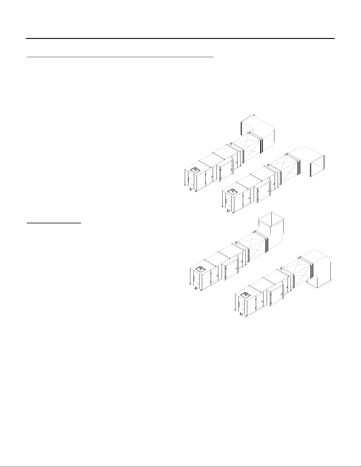
For Non Recirculating applications, all air to this unit must be drawn directly from the outdoors.
Recirculation of room or building air is not permitted.
The outside air intake of the make-up air unit shall be located in accordance with local building code
provisions for ventilation air. Not withstanding those requirements the intake should be located as far as
possible away from any exhaust discharge,
plumbing vent or other source of contaminants in
order to prevent the induction of contaminants.
The outside air intake of the make-up air unit shall
not be located within 20 ft (6 m) horizontally of the
vertical plane in which combustible gas, vapor or
dust is present.
This equipment shall be installed so that in the
event the make-up air shut down causes a hazard
to other fuel burning equipment in the building, the
unit shall be interlocked to open balancing inlet air
dampers or equivalent.
INLET DUCTING
A pre-purge cycle shall be used to provide at least
four air changes in the ducting before an ignition
attempt.
Units with ducted outside air inlet shall have straight
duct directly attached to the unit of a length at least
1½ times the unit height or 2 times the unit width,
which ever is greater.
Field constructed intake accessories should be
properly designed to minimize the entry of snow
and rain. If there is doubt about the installation of
this product with respect to the application, contact
Engineered Air.
IOM-26 13 of 33 Oct 12 R4
Page 14
A HE, DE & RE MANUAL
Warning:
On heaters which recirculate room air, outside ventilation air must be provided
in accordance with the information shown on the name plate.
FIELD INSTALLED DAMPERS
At times it is desirable to have a damper external to the unit. In some cases the operation of these
dampers may cause a “gas trap”, which is a volume of air trapped within the unit between damper sections.
In this case a pre-purge cycle shall be used to provide at least four air changes in the ducting before an
ignition attempt.
Where external dampers of any kind are used, the make-up air unit shall be electrically interlocked with the
dampers in such a way as to prevent ignition attempt unless the dampers are fully open.
3 Position inlet dampers on dual capacity units:
On low capacity: the profile plate bypass damper should be closed. The outside air inlet dampers
should be open about 1" (25mm).
On high capacity: the profile plate bypass damper should be open and the outside air inlet dampers
should be fully open.
HE WITH RECIRCULATING MIX BOX OR RE SERIES (IN USA ONLY).
DE WITH RECIRCULATING MIX BOX (CANADA OR USA).
Recirculation of room air in HE, DE & RE units may be hazardous in the presence of:
A. Flammable solids, liquids, and gases and
B. Explosive material (i.e.: grain dust, coal dust, gunpowder, etc.) and
C. Substances which may become toxic when exposed to heat (i.e.: refrigerants, aerosols, etc.)
Recirculation units are not recommended in uninsulated or poorly insulated buildings where
outside temperatures fall below 32°F (0°C).
The ventilation air (outside air) shall be ducted directly to the heater. The outside air intake shall
not be located within 20 ft (6 m) horizontally of the vertical plane in which combustible gas, vapor
or dust is present.
Excessive recirculation or insufficient ventilation air (outside air), which results in inadequate
dilution of the products of combustion products generated by the recirculating HE with mix box or
RE heater, may create hazardous concentrations of carbon dioxide, carbon monoxide, nitrogen
dioxide, and other combustion products in the heated space.
If propane powered forklift trucks or other fossil fuel powered equipment are utilized in the
conditioned space, additional ventilation requirements for the facility must be addressed
separately.
IOM-26 14 of 33 Oct 12 R4
Page 15

A HE, DE & RE MANUAL
DE PROCESS HEATER INSTALLATION REQUIREMENTS
1. DE Series process air heaters require the installation of a manual emergency gas shutoff valve in an
appropriate location that allows access to this valve to shut off the fuel to this heater in case of a fire or
explosion at the heater or the space served by the heater.
2. If the space served by this DE Series process air heater can be entered by personnel:
a. The access opening(s) to the space shall be equipped with door interlock switch(es) to prevent the
operation of the heater during a bake cycle when an access door is opened.
b. It is recommended that warning signage be posted each access opening with wording equivalent
to:
Do not enter this space until the ventilation/cool down cycle is complete.
3. If the space served by this DE Series process air heater is intended to be entered by personnel
following a bake cycle, the space should be ventilated to purge contaminants from the space and cool
the products to avoid a burn hazard. The cool down cycle control is normally provided as part of the
remote panel. See the unit function and wiring diagrams.
4. If this DE Series process air heater has a re-circulating mode that draws air from the space being
served, filters shall be provided in the return air duct system that are approved by the authority having
jurisdiction if there is airborne particulate matter that could be detrimental to the operation of the heater.
If airborne particulate matter could accumulate in the duct system in the re-circulating mode, the return
air duct system shall be installed with doors, panels, or other means to facilitate inspection,
maintenance, cleaning, and access to fire protection devices. Periodic inspection and cleaning of the
re-circulating air duct system is required
The duct systems shall be designed to prevent recirculation of insufficiently diluted products of
combustion.
5. The minimum amount of ventilation air supplied to the space in re-circulation mode must exceed 200
cfm per 1000 cfh of natural gas based on the maximum capacity of the heater plus an allowance to
sufficiently dilute the VOC’s created by the process to maintain the lower explosive level (LEL) below a
25 percent threshold value. Refer to the unit rating plate for this information.
6. If this DE Series process air heater serves a paint booth refer to the unit function and wiring diagram
provided for the following:
a. Wiring the paint spraying equipment interlock. This prevents operation of the paint spraying
equipment unless the process heater is operated in the ventilation air mode.
b. An automatic purge (ventilation) air mode is provided for an minimum of three (3) minutes or a
minimum of four (4) air changes of the paint booth volume, whichever is greater at the start of the
bake or drying cycle with the paint spraying equipment locked out.
c. Interlock between the exhaust fan and heater fan.
IOM-26 15 of 33 Oct 12 R4
Page 16
A HE, DE & RE MANUAL
Caution:
Temporary Power Generation
The warranty will be void if the voltage being fed from any temporary
generator is not within 10% of the nominal rated nameplate voltage and
voltage imbalance shall be limited to 2%. A power monitor shall be installed
by others to properly monitor power quality and conditions.
All generator sets shall be provided with overcurrent and earth-fault
protection. The protective apparatus should be capable of interrupting,
without damage, any short-circuit current that may occur.
Warning:
No unspecified external load shall be added to the control transformer
circuit(s) or to the main power circuit(s).
7. Refer to the unit function and wiring diagram provided for the lighting interlock of the served space
during heater operation in the bake cycle mode.
8. For Non Re-circulating applications, all air to this unit must be drawn directly from the outdoors.
EXHAUST FAN / RELIEF AIR PROVISIONS
Adequate relief shall be provided so as to prevent building over-pressurization when the ventilation system
is operating at its full rated capacity. This can be accomplished by interlocking a powered exhaust system;
by providing properly sized relief openings; or by taking into account, through standard engineering
methods, the structure’s designed infiltration rate; or by a combination of these methods.
LOW LIMIT FREEZE PROTECTION
If an optional low-temperature control system (low limit) is not an integral part of the heater, it is
recommended that a low limit control be installed if this unit is being installed a geographic area subject to
freezing temperatures. The low limit can provide freeze-up protection in the event of burner shutdown.
ELECTRICAL INSTALLATION
DO NOT install anything that will interfere with equipment access or the rating plate.
The unit must be electrically grounded and all wiring must be installed in accordance with the National
Electrical Code, ANSI/NFPA 70, and/or the Canadian Electric Code CSA 22-1 and to the approval of the
authorities having jurisdiction. THE FLOOR OF THE UNIT HAS BEEN MADE WATER-RESISTANT. DO
NOT CUT OR DRILL HOLES IN THE FLOOR OR USE PENETRATING FASTENERS. Field wiring
diagrams, internal wiring diagrams and operating functions are included in the control cabinet. The power
requirements are indicated on the rating plate. Where field wiring of control circuits is required, take care to
size the field wiring for a maximum 10% voltage drop. The control circuit ampacity is noted on the field
wiring diagram. See the field wiring diagram for requirements for shielded or twisted pair wire for solid state
devices.
IOM-26 16 of 33 Oct 12 R4
Page 17
A HE, DE & RE MANUAL
Circuit
Load
(Amps)
(1)
Maximum Total Length of Run
< 50 Ft
< 100 Ft
< 150 Ft
< 200 Ft
< 250 Ft
< 300 Ft
< 350 Ft
< 400 Ft
< 450 Ft
< 500 Ft
(~ 15 m)
(~ 30 m)
(~ 45 m)
(~ 60 m)
(~ 75 m)
(~ 90 m)
(~ 105 m)
(~ 120 m)
(~ 135 m)
(~ 150 m)
1
16 AWG
16 AWG
16 AWG
16 AWG
16 AWG
16 AWG
14 AWG
14 AWG
14 AWG
12 AWG
2
16 AWG
16 AWG
16 AWG
14 AWG
12 AWG
12 AWG
12 AWG
10 AWG
10 AWG
10 AWG
3
16 AWG
16 AWG
14 AWG
12 AWG
12 AWG
10 AWG
10 AWG
10 AWG
4
16 AWG
14 AWG
12 AWG
10 AWG
10 AWG
10 AWG
5
16 AWG
12 AWG
12 AWG
10 AWG
6
16 AWG
12 AWG
10 AWG
10 AWG
7
14 AWG
12 AWG
10 AWG
8
14 AWG
10 AWG
10 AWG
9
14 AWG
10 AWG
10
12 AWG
10 AWG
11
12 AWG
10 AWG
12
12 AWG
10 AWG
13
12 AWG
14
12 AWG
15
12 AWG
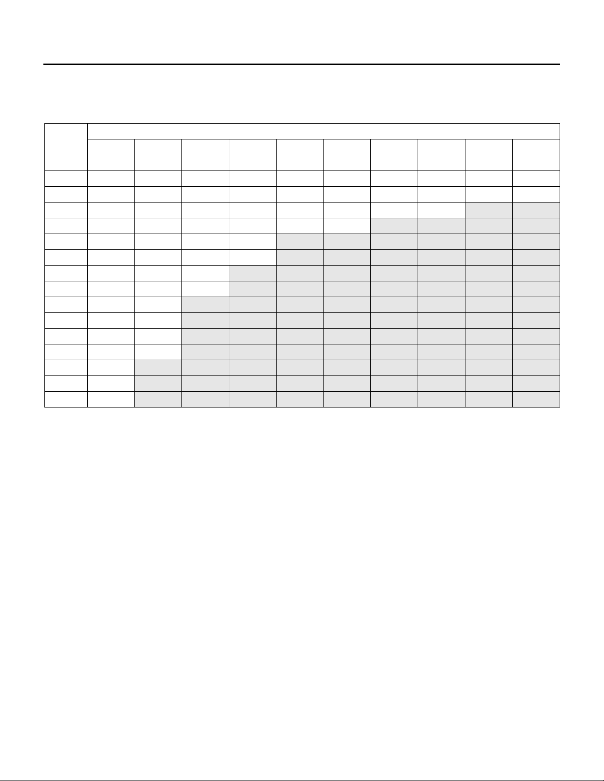
Recommended 24V Field Wiring Size:
Copper conductors only
Notes:
1) The field wiring load depends on the actual load on a particular control circuit the field wiring is
connected to. Refer to the internal wiring diagram of the unit.
2) The table above is based on a maximum 10% voltage drop on a 24V control circuit. Wire size was
calculated using the following formula:
CM = (25 x I x L ) / V
Where CM is circular mils of conductor for a constant load of I amps, wire length L in feet from the
unit to the field device and back, and voltage drop V.
When connecting to a three phase power supply, check for the correct rotation of all motors and fans. If the
rotation is incorrect, reverse the rotation at the incoming power only. All electrical conduit outlets in the
control panel must be sealed to prevent moist building air from migrating to the control panel.
All penetrations through the unit walls must be caulked and sealed to prevent air and/or water from
entering the unit.
IOM-26 17 of 33 Oct 12 R4
Page 18
A HE, DE & RE MANUAL
Caution:
Use a backup wrench on threaded coil connections when installing piping.
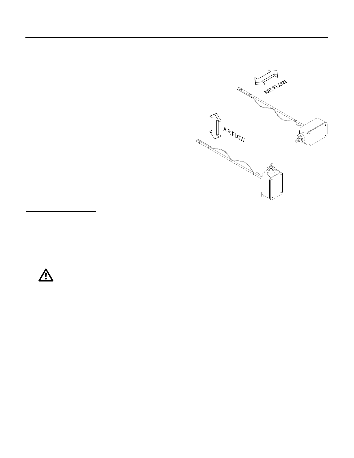
DUCT MOUNTED TE-6000-EA3 TEMPERATURE SENSOR
Some applications require field installed discharge air
sensors.
The sensor strip must be parallel to the air flow. The
sensor should be mounted near the center of a straight
duct 5 to 10 feet (1500 to 3000mm) downstream of the
supply air connection to the Engineered Air unit. Avoid
installing near duct transitions or elbows.
Use twisted pair or shielded wiring. The ground shield
should be grounded only at the unit control panel end.
Protect the opposite end ground and any unused wire with
electrical tape.
When installing an Engineered Air TE-6000-EA3 duct
mounted temperature sensor, the sensor strip must be
parallel to the air flow as shown.
COIL CONNECTIONS
This equipment may require field connection of water, steam or refrigerant coils. For proper operation
airflow must be counterflow to the flow of the fluid. The inlet water connection is normally at the bottom of
one header and the outlet water connection at the top of the other header. The steam connection is at the
middle of the supply header and the condensate is at the bottom of the other header.
For refrigerant coils, all piping is to be installed by a qualified refrigeration mechanic. All refrigeration
specialties shall be installed using good refrigeration installation and design practices.
Recovery, reuse, recycling, reclamation, and safe disposal of refrigerant is the only acceptable practice
today. Venting of refrigerant into the atmosphere during installation or servicing is unacceptable. To avoid
damage, use an accepted refrigerant recovery system whenever removing refrigerant. When working with
refrigerants you must comply with all local government safety and environmental laws.
IOM-26 18 of 33 Oct 12 R4
Page 19
A HE, DE & RE MANUAL
Warning:
Failure to properly trap each connection can result in drain pan flooding,
standing water in unit, building damage, injury or death, cause poor air
quality or other problems.
H1
H2
H1
H2
VENT & PRIMING
FUNNEL
TO DRAIN
OPTIONAL
CLEAN OUT
ATMOSPHERIC
DRAIN TRAPS
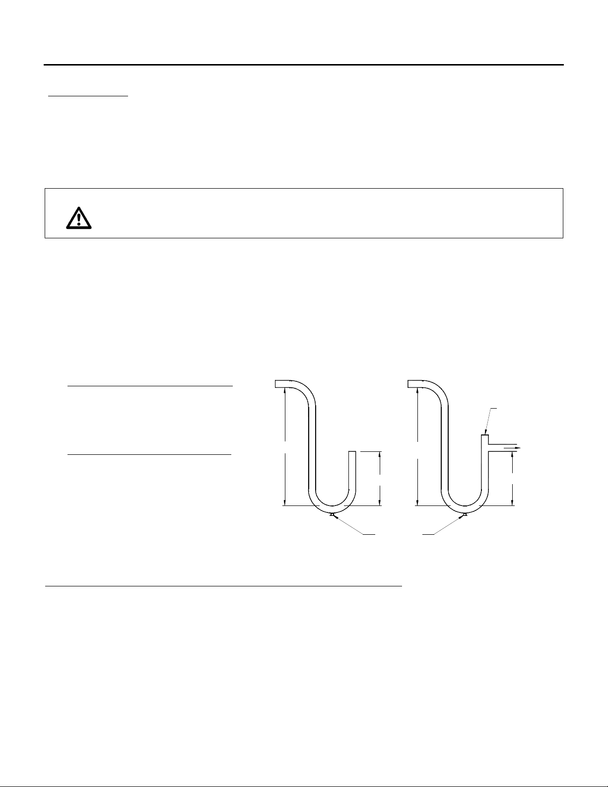
Each drain connection requires a separate drain trap supplied and installed by the contractor. For a trap to
work properly, it must be primed. During freezing periods, primed traps may need to be heat traced or drain
and plug the trap when not in use. If a drain connection has a smaller pipe inside, connect to the outer pipe
only. Ensure that the trap is of adequate depth to operate against a static that includes the extra pressure
drop for dirty filters.
In some applications (e.g. heat recovery units) there may be additional drain connections inside the curb
intended to be connected to the building drainage system. These drains must be connected and properly
trapped.
Cooling coil drain pans may have multiple drain connections extending outside the unit casing. Multiple
drains may be connected to a common drain providing that each drain is individually trapped and vented to
avoid problems from drains in different pressure zones. The drain must be properly sized and sloped.
Size drain trap with the following minimum requirements:
a) Units With Draw Through Drain Pans:
H1 = Negative Static† x 1.5 + 3.5” (89mm)
H2 = Negative Static† x 0.75 + 2.5” (64mm)
b) Units With Blow Through Drain Pans:
H2 = Maximum Positive Static† x 1.5
H1 = H2 + 0.5” (13mm)
† Static Water Column (WC) in inches or mm
including fully loaded filters.
Ensure adequate clearance for properly sized drain traps.
FLUSHING AND DEGREASING OF WATER AND GLYCOL COILS
Coil tubing may contain material or residue from manufacturing, transportation or storage. To prevent
possible damage to other components in the system, the coils must be flushed and degreased. Consult a
qualified water treatment specialist.
IOM-26 19 of 33 Oct 12 R4
Page 20
A HE, DE & RE MANUAL
Warning:
This unit is connected to high voltages. Electrical shock or death could occur
if instructions are not followed. This equipment contains moving parts that
can start unexpectedly. Injury or death could occur if instructions are not
followed. All work should be performed by a qualified technician. Always
disconnect and lock out power before servicing. DO NOT bypass any
interlock or safety switches under any circumstances.
HEAT TRANSFER FLUIDS
The coil(s) provided have been selected for use with a specific heat transfer fluid as shown on the
Submittal Record. Use of other fluids will result in different performance and can damage the coil(s).
It is imperative to properly select and apply heat transfer fluids used in heating and cooling systems.
Untreated, improperly treated or improper use of fluids or use of fluids not approved for use in commercial
heating and cooling systems can damage coils and system components. For selection and application of
heat transfer fluids, always follow the manufacturers’ recommendations including treatment, mixing and
filling. Warranty will be void if coil damage results from misapplication or improper treatment of the heat
transfer fluid.
Some systems may use CPVC piping. Do not use propylene glycol with CPVC.
BEFORE START-UP
Remove tie-down bolts, straps and blocks on fan and compressor vibration isolators, tilt equipped heat
pipes and enthalpy/desiccant wheels if supplied.
START-UP CHECK LIST
The start-up and operation must be in accordance with safe practices. Start-up must be performed by
qualified personnel. Complete attached start-up record.
1. Set all associated electrical switches, controls, thermostats and main disconnect switch to “OFF”
position.
2. Close all manual valves and field piping valves.
3. Confirm that all shipping materials have been removed. See any supplemental instructions shipped
with the unit to help identify possible locations.
4. Check all bearings, drive and fan set screws for tightness. See TABLE I
5. Check drive alignment and belt tension. Refer to Maintenance, page 26.
6. Inspect all electrical wiring, both field and factory installed, for loose connections. Ensure fire alarm
contact is installed, or jumpered if not required.
7. Turn disconnect switch ON (control switch is still off) and check the supply voltage. Voltage must be
within 10% of rating plate. If not, contact the installing electrical contractor and have the voltage
condition corrected before continuing start-up.
8. Check all fan motors for correct rotation. If incorrect, reverse rotation on incoming power only.
IOM-26 20 of 33 Oct 12 R4
Page 21

A HE, DE & RE MANUAL
9. Set thermostat or controller to the “OFF” position and turn unit control switch “ON”.
10. Check the amperage draw of each motor and compressor. Refer to unit or motor rating plate for full
load amps. At the unit, check and record the voltage while it is running. For 3 phase power the
phase to phase voltage imbalance should be less than 2%. A 2% voltage imbalance can cause up
to a 10% current imbalance that will overheat motor windings.
To calculate voltage imbalance (NEMA method) refer to the following example:
Phase to phase voltage readings: 235V 236V 230V
The average Voltage between legs is 233.7V (235+236+230)/3
Highest voltage deviation from average is: 233.7V – 230V = 3.7V
Voltage imbalance percentage = Highest deviation divided by average X 100
3.7 / 233.7 x 100 = 1.6% This imbalance is less than 2% and therefore is OK
If voltage imbalance is greater than two percent (2%), turn off main disconnect and contact
the installing electrical contractor to have the voltage condition corrected.
11. Enable heating and/or cooling; refer to unit function for correct sequence and operation.
12. Confirm field wiring voltage drop is less than 10% when equipment is operating.
13. For the unit to operate properly a system air balance must be performed to ensure correct air flow.
Failure to do so can damage the equipment and/or building and can be a cause of poor indoor air
quality.
14. Some units are equipped with an adjustable coil air bypass. This must be field adjusted during the
system air balance to ensure proper air flow across the coil. Adjust the bypass to achieve coil
pressure drop as stated on the submittal and/or the unit function sheet.
15. Set all controls to the settings indicated on the wiring diagram.
16. Re-install all access panels.
17. Remove any packing material or debris and dispose appropriately.
IOM-26 21 of 33 Oct 12 R4
Page 22
A HE, DE & RE MANUAL
Warning:
This unit is connected to high voltages. Electrical shock or death could occur
if instructions are not followed. This equipment contains moving parts that
can start unexpectedly. Injury or death could occur if instructions are not
followed. All work should be performed by a qualified technician. Always
disconnect and lock out power before servicing. DO NOT bypass any
interlock or safety switches under any circumstances.
Warning:
Proper commissioning and start-up of the air handling system is the
responsibility of the installing contractor. It is recommended that an air
balance be completed by a certified air balancing contractor to insure the air
volume being delivered matches the unit rating plate. Failure to perform a
proper air balance can cause injury or death, damage to the equipment,
property damage, system operational problems, or be a cause of poor air
quality. Moisture carry over can result from improper air flow.
OPERATION
This unit may incorporate one or more functions and a variety of controls and options to suit individual
requirements. A description of the unit functions and options is shown on the Electrical Data Sheet and
unit wiring diagram. Carefully check your wiring diagram to verify that all remote controls are properly
located and correctly field wired.
Some equipment may contain programmable unitary controllers or programmable logic controllers (PLC).
Additional information can be obtained from the specific programmable control manufacturer. Often this
information is available from the control manufacturer’s website.
IOM-26 22 of 33 Oct 12 R4
Page 23
A HE, DE & RE MANUAL
Manufacturer
Pipe size (in.)
Model
Maximum leakage rate
(bubbles/10sec.)
Honeywell
1, 1¼
V4943, V8943
13
1½, 2
V4943, V8943
16
¾, 1, 1¼, 1½
V5055, V5097
14
2, 2½ ,3
V5055, V5097
24
ASCO
¾
K3A551/651
6
1
K3A551/651
6
1 ¼
K3A551/651
7
1 ½
K3A551/651
9
1/2(13mm)
CUTAT
45DEGREE
ANGLE
JARORGLASSWITHWATER
1/4IN (6MM)ALUMINUMOR
COPPERPILOTTUBING
1/4 (6MM)FLEXIBLETUBING
GASSUPPLY
UPSTREAM
MANUAL
GASCOCK
PVR SSOV
MANUAL
GASCOCK
DOWNSTREAM
TEST
TAP
LEAK
A B C ED
1
CAN ALSO BE A PERMANENT PETCOCK.
PRV = PRESSURE REGULATING VALVE.
2
USE ONLY ONE OF THE DOWNSTREAM TAPS ON THE SSOV.
SSOV = SAFETY SHUTOFF VALVE.
4
3
2
3
4
DOWNSTREAM
GASCOCK
MANUAL
1
F
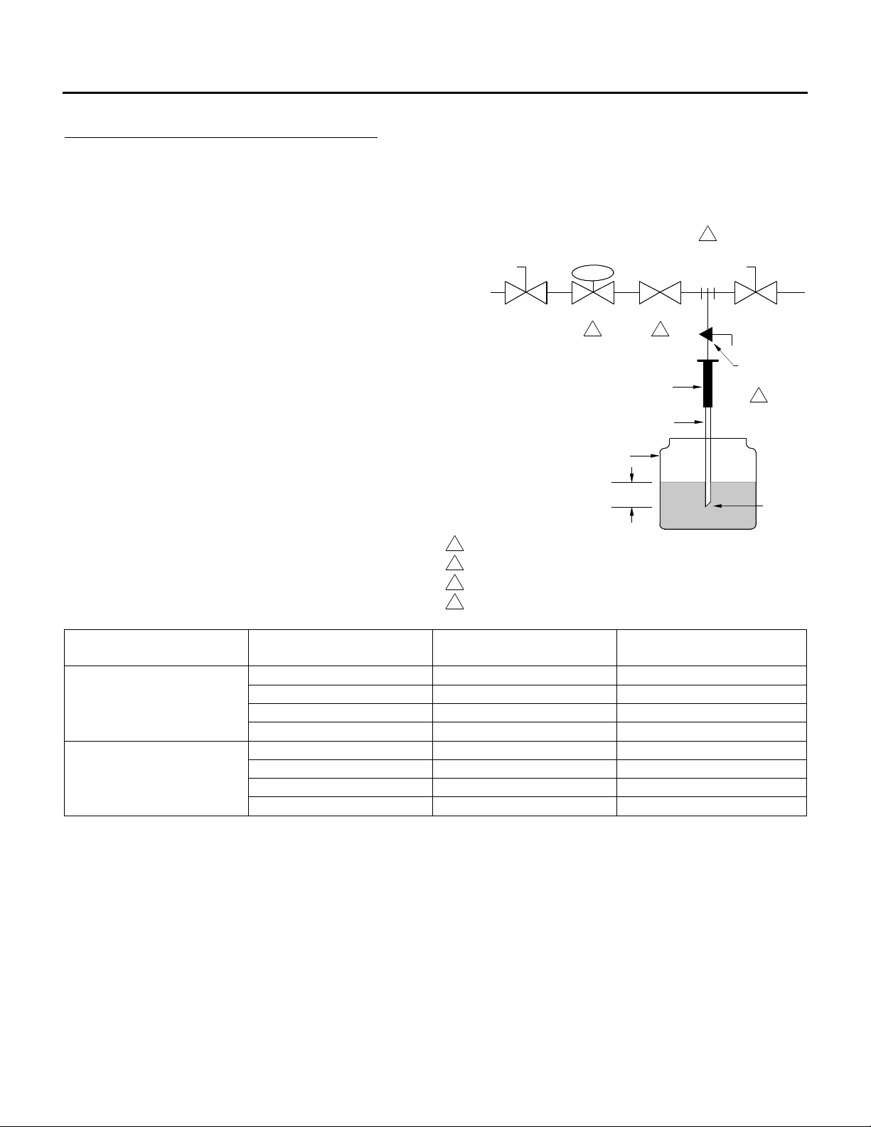
SAFETY SHUTOFF VALVE LEAK TEST:
Safety shutoff valves require a qualified technician to perform a leak (bubble) test to determine tightness of
closure on a least an annual basis. A very small amount of leakage is normal. Valve leakage rates
exceeding those noted in the table below require repair or valve replacement.
1. De-energize the control system.
2. Close the upstream manual gas valve.
3. Connect a ¼” (6mm) tube to the outlet
pressure tap on the safety shutoff valve.
4. Immerse the opposite end of the ¼” (6mm)
tube (cut to a 45° angle) vertically ½” (13mm)
into a clear container of water.
5. Count the number of bubbles appearing
during a 10 second period.
6. If the bubble rate is greater than that noted in
the table repair or replace the valve.
7. If bubble rate is less than noted in the table,
remove the ¼” (6mm) tube, reconnect the
outlet pressure tap plug.
8. Energize the control system and open
upstream manual gas valve.
9. After testing check all piping connections and
plugs for external leakage.
The table below indicates the maximum number of
bubbles in relation to the size and type of valve.
IOM-26 23 of 33 Oct 12 R4
Page 24

A HE, DE & RE MANUAL
OPERATIONAL CHECK
CALL A QUALIFIED SERVICE PERSON FOR SERVICE.
1. Turn on main and pilot valve up stream of manual firing shut-off valves and check for leaks on unit
piping.
2. Check for leaking main and pilot valve seats by closing the manual firing valve and safety shut-off
valve. Connect one end of a hose to the pressure tap between the manual firing valve and safety
shut-off valve and submerge the other end in a cup of water. If bubbles appear, correct leak.
3. The pilot pressure is preset in the factory and should not require adjustment.
4. To start the blower, set the remote manual switches to the “on” position. Switch on the exhaust
system to make the exhaust interlock. The damper should begin opening. When fully open, the
damper blade will make an end switch that will start the blower. If the control system includes an
auto bypass low limit, for convenience, the low limit can be jumpered out during start-up and
adjustment of other controls. Remove the jumper when start-up is completed and check the low
limit and bypass function.
5. To start the heat, open the pilot manual firing valve and turn on the heat switch on the remote
panel. The pilot should attempt ignition. If an attempt at ignition is made and lockout occurs, reset
the flame relay and visually check a second time to confirm that there is a pilot flame. If there is
pilot flame for 8 seconds before flame ignition control lockout, a safety control in the flame sensing
circuit is likely the problem. For example a lockout will occur if the air pressure switches are not
made. Refer to separate trouble shooting guide for additional information. Also check spark rod
and flame rod to see if the ceramic is wet, cracked or dirty as any one of these things can cause
lockout. The gap on the spark rod is 3/32". If the unit has a Fireye M SERIES II flame ignition
control, a D.C. voltmeter micro ammeter is required to check the flame rod signal. A set of test
jacks is provided in the flame ignition control for this test. The signal should be at least 10 VDC. If
the signal is less than 10 VDC and a pilot flame is present, refer to the separate trouble shooting
guide.
6. After achieving a pilot that burns constantly while the blower is running, check the main gas valves
for operation while the main manual firing valve is CLOSED. Turn the heat switch off. The pilot will
then go out. Place a pressure gauge between the automatic valve(s) and the manual firing valve.
Switch on the burner. If the pilot comes on and proves properly, the main automatic valve should
open and the gauge should register pressure. The pressure gauge may read negative at reduced
inputs. If the main valve(s) do not open, check for a wiring error or a defective component.
7. Test for main flame ignition. With the main automatic valve open, manually open the firing valve
from closed to open. Main burner ignition should take place approximately one quarter of a turn
from closed to open.
8. The heater has been designed and built for the specific air volume, external static pressure (duct
pressure) and air temperature rise shown on the rating plate and in the submittal record. No
adjustment of the profile plate should be required.
IOM-26 24 of 33 Oct 12 R4
Page 25

A HE, DE & RE MANUAL
9. Do not adjust the main pressure regulator (appliance regulator). The firing rate has been factory
set and should not require any adjustment. The air temperature rise should be as listed on the
nameplate. If not, the air volume through the unit should be adjusted. This may be accomplished
by adjusting the blower speed, by balancing dampers, or both. The air temperature rise and unit
inlet gas pressure should be measured when the modulating valve is wide open.
The modulating valve can be made to stay wide open by turning the modulating temperature control
up to its maximum setting and removing its sensing element from the air stream and exposing it to
a cool temperature. If unit inlet gas pressure is less than minimum inlet pressure on the unit label,
the unit may not have enough heat on the coldest (design ambient) days. With proper airflow the
flame should be approximately 16" long and tipped with a reddish orange flame. If the flame is
much longer and mostly yellow, or it the flame is much shorter and florescent blue only, check the
separate trouble shooting guide for the necessary adjustments.
10. Confirm gas inlet pressure matches unit rating plate at high fire.
11. Perform a flame supervision check as follows: With the burner firing, close the main manual firing
valve and the pilot firing valve. The automatic valves should close within 4 seconds and the flame
ignition control should lock out within 10 to 15 seconds. To return to normal operation, reset the
flame safeguard and open the manual valves.
12. Check for leaks on unit piping with unit firing.
13. Check the low limit (optional) by adjusting the setting above the discharge set point until the unit
shuts down. The low limit will not shut the units down until the bypass timer contact has opened.
14. Return the low limit and temperature controller to their proper settings (see control settings).
15. The blower motor and particularly the belt, should be checked after the previous tests and
adjustments have been completed. The belts have a tendency to stretch during the first few weeks
of operation and may need to be adjusted. The amperage draw of the motor should be checked
with an ammeter and should not exceed the rated amperage stated on the motor rating plate.
Otherwise, the motor overload will lockout the motor.
If the installation has an exhaust fan, adjust the exhaust air to match the supply air within ± 10%.
CONTROL SETTINGS
The following settings of the adjustable controls are acceptable for most applications. Refer to unit function
and wiring diagram for settings specific to your unit.
Single and two stage ductstat: 55 – 70°F (13 – 21°C).
Single, two stage and modulating space thermostat: 68 – 74°F (20 –23°C).
Remote temperature selector: 60 – 70°F (16 – 21°C).
IOM-26 25 of 33 Oct 12 R4
Page 26
A HE, DE & RE MANUAL
Warning:
This unit is connected to high voltages. Electrical shock or death could occur
if instructions are not followed. This equipment contains moving parts that
can start unexpectedly. Injury or death could occur if instructions are not
followed. All work should be performed by a qualified technician. Always
disconnect and lock out power before servicing. DO NOT bypass any
interlock or safety switches under any circumstances.
Warning:
Follow the cleaning instructions and recommended inspection schedule to
reduce the risk of mold or other bacterial growth. Property damage or
personal injury claims may result from mold or biological growth arising from
improper installation, inadequate maintenance, or failure to inspect.
Engineered Air has no responsibility for and makes no express or implied
warranties regarding mold or bacterial growth or any other indoor air quality
issues. If mold or biological growth is present, determine and fix the cause.
Properly remove and dispose of the contamination. Properly clean and
sanitize the affected area using only approved sanitizers suitable for HVAC
equipment.
Caution:
Label all wires prior to removal when servicing controls or critical
components. Wiring errors can cause improper and dangerous operation.
Verify proper operation after servicing.
MAINTENANCE
To provide a maintenance history, It is recommended that the owner have a maintenance file for each unit.
The following maintenance instructions are to be carried out each spring and fall or as otherwise
indicated by qualified service personnel.
ELECTRICAL
1. Check all wiring for loose connections.
2. Check voltage at unit (while in operation).
3. Check amperage draw against unit rating plate.
4. Where possible, all contactors should be inspected to ensure that contacts are clean and are
making good contact. If contacts are abnormally pitted or burned badly, replace contactor. Single
phasing and motor burnouts can result from bad contacts.
IOM-26 26 of 33 Oct 12 R4
Page 27
A HE, DE & RE MANUAL
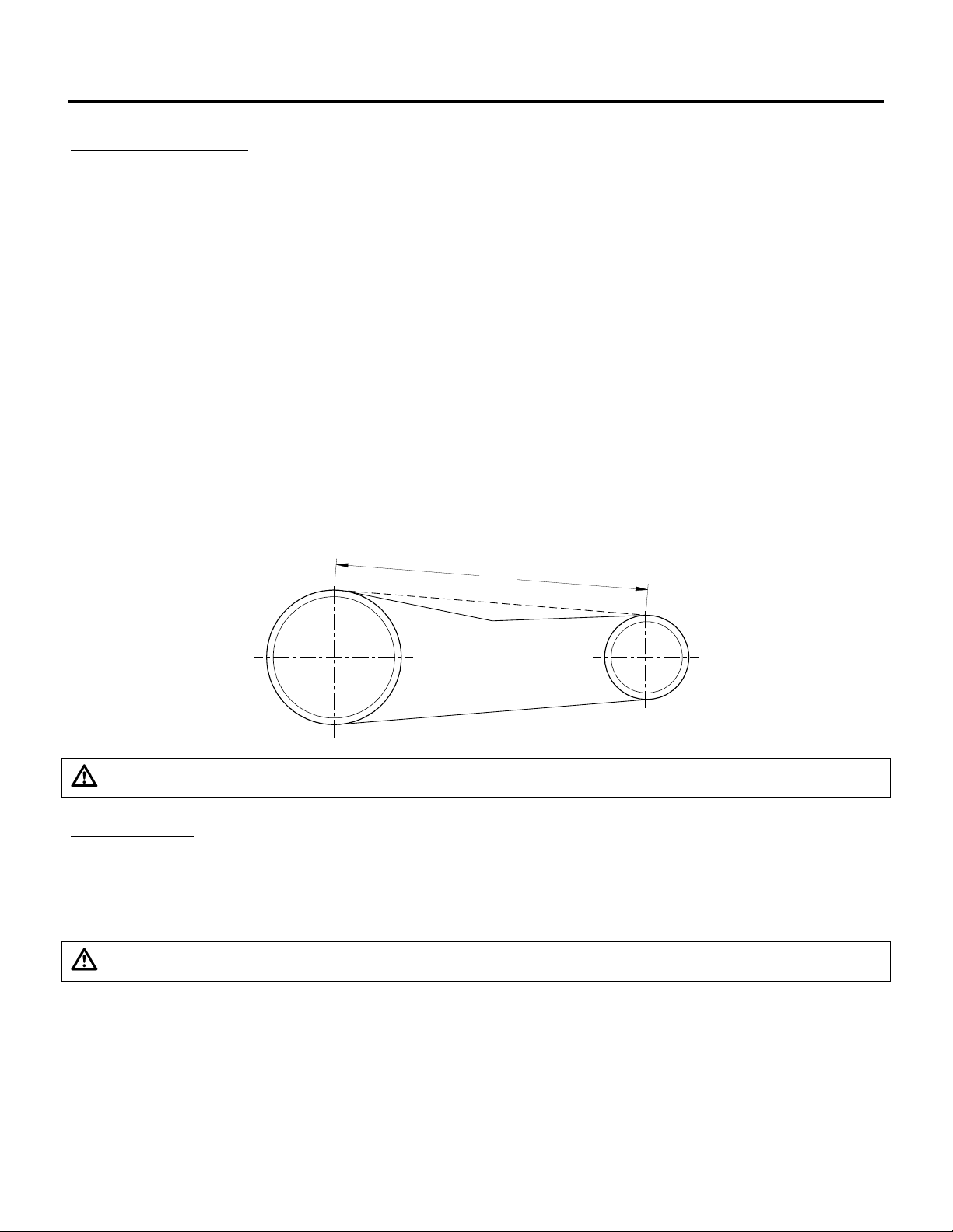
DEFLECTION
SPAN
BELT ADJUSTMENT
For maximum belt and bearing life, pulley alignment and belt tension must be properly maintained. Only
replace with belts of the proper type and size.
NOTE: If belts are too tight or improperly aligned, the life expectancy of the motor(s), fan bearings and
belt(s) are reduced.
Alignment: Pulleys must be aligned to within 1/16” per foot (1mm per 760mm) of span.
FOR FANS EQUIPPED WITH SPIDER BRACKETS:
A properly adjusted V-belt rides the inside of the pulley faces. Because the sides of the belt wedge in the
pulleys, the V-belt does not have to be extremely tight. It should be as loose as possible without slipping in
the pulley grooves.
Belt deflection: 3/4 “ (19mm) for each foot (300mm) of span between the pulleys.
FOR FANS EQUIPPED WITH PILLOW BLOCK BEARINGS:
Belt Deflection: Allow 1/64” (0.4mm) of deflection for each 1” (25.4 mm) of span length.
CAUTION: Excessive belt tension is the most frequent cause of belt wear, bearing wear and noise.
SET SCREWS
Check set screws on fan wheel, fan bearings, fan and motor pulleys for looseness on the shaft. Tighten
where required. IT IS IMPORTANT TO PERFORM THIS CHECK BEFORE INITIAL START-UP, AFTER A
RUN-IN PERIOD OF 2 WEEKS AND THEN ON 4 MONTH INTERVALS.
CAUTION: OVERTIGHTENING SET SCREWS CAN DAMAGE BEARINGS.
IOM-26 27 of 33 Oct 12 R4
Page 28
A HE, DE & RE MANUAL
Shaft diameter
NTN
KOYO
NTN
KOYO
DODGE
Type
UC SERIES
(set screw)
UK SERIES
(adapter sleeve locknut)
SC 203-215 SERIES
3/4" (19mm)
35 in-lb (3.9 Nm)
35 in-lb (4.0 Nm)
Install the washer and lock nut;
tighten the nut fully by hand.
Apply a punch or screw driver
into the notch of the nut and
tap it with a hammer. Stop
tapping after the nut has turned
60° to 90°.
Do not strike the seal.
Bend the tab on the rim of the
washer, which is in line with the
notch of the nut.
If a tab does no line up with a
notch, tighten the nut further.
DO NOT BACK THE NUT
OFF.
66 - 80 in-lb (7.5 - 9 Nm)
1" (25mm)
35 in-lb (3.9 Nm)
35 in-lb (4.0 Nm)
126 - 156 in-lb (14 -18 Nm)
1 3/16" (30mm)
43 in-lb (4.9 Nm)
35 in-lb (4.0 Nm)
126 - 156 in-lb (14 -18 Nm)
1 7/16" (37mm)
51 in-lb (5.8 Nm)
75 in-lb (8.5 Nm)
126 - 156 in-lb (14 -18 Nm)
1 11/16"(43mm)
69 in-lb (7.8 Nm)
75 in-lb (8.5 Nm)
228 - 272 in-lb (26 -31 Nm)
1 15/16"(49mm)
69 in-lb (7.8 Nm)
155 in-lb (17.5 Nm)
228 - 272 in-lb (26 -31 Nm)
2 3/16"(56mm)
87 in-lb (9.8 Nm)
155 in-lb (17.5 Nm)
228 - 272 in-lb (26 -31 Nm)
2 7/16"(62mm)
147 in-lb (16.6 Nm)
155 in-lb (17.5 Nm)
228 - 272 in-lb (26 -31 Nm)
2 11/16"(68mm)
173 in-lb (19.6 Nm)
248 in-lb (28.0 Nm)
228 - 272 in-lb (26 -31 Nm)
2 15/16"(75mm)
173 in-lb (19.6 Nm)
248 in-lb (28.0 Nm)
228 - 272 in-lb (26 -31 Nm)
Bearing Temperature
° F (°C)
Re-Greasing Interval
Clean
Dusty
Dusty & Wet
Under 120 (50)
2 ½ Years
Yearly
4 Months
Under 158 (70)
Yearly
4 Months
1 Month
Shaft Dia.
3/4"
(19mm)
1"
(25mm)
1 3/16"
(30mm)
1 7/16"
(37mm)
1 11/16"
(43mm)
1 15/16"
(49mm)
2 7/16"
(62mm)
2 15/16"
(75mm)
Grease
0.06 oz.
(1.8g)
0.12 oz.
(3.3g)
0.20 oz.
(5.6g)
0.23 oz.
(6.5g)
0.27 oz.
(7.7g)
0.36 oz.
(10.3g)
0.53 oz.
(14.9g)
1.00 oz.
(31.0g)
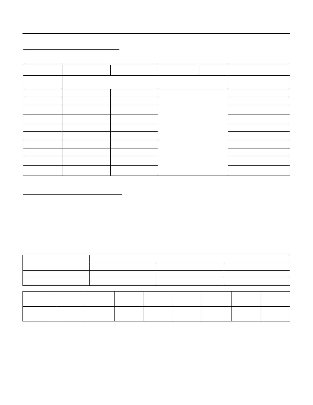
BEARING SETSCREW TORQUES
TABLE I
Refer to bearing manufacturers’ literature for all other types of bearings.
LUBRICATION OF FAN BEARINGS
Some fans have permanently lubricated sealed ball bearings which should not require lubrication. These
bearings are factory packed 30 to 50% full. Bearings that require lubrication should be greased while
the bearing is rotating slowly, with the following quantities of a lithium base lubricant. DO NOT
OVERGREASE. DO NOT USE NON-LITHIUM BASED GREASE.
Extended lubrication lines may be provided. Tubing is not factory filled.
RECOMMENDATIONS FOR BALL BEARINGS
For additional information refer to the fan and/or bearing manufacturers’ literature.
IOM-26 28 of 33 Oct 12 R4
Page 29
A HE, DE & RE MANUAL
Speed (RPM)
500
1000
1500
2000
2500
3000
3500
4000
4500
Shaft DIA.
½” - 1 1/
16”
6 6 5 3 3 2 2 2 1
1 15/16” – 2 7/16”
6 5 4 2 2 1 1 1 1
2 11/16” – 2 5/16”
5 4 3 2 1 1 1
3 7/16” – 3 15/16”
4 3 2 1 1
Speed (RPM)
500
1000
1500
2000
2500
3000
3500
4000
4500
Shaft DIA.
1 3/16” – 1 7/
16”
6 4 4 2 1 1 1
1 1/2
1 11/16” – 2 3/16”
4 2 1 1/2
1 1/2 1/2 1/2 1/2 1/2
2 7/16” – 3 7/16”
3
1 1/2
1 1/2 1/2 1/4 1/4
3 15/16” – 4 15/16”
2 1/2
1 1/2 1/4
LUBRICATION OF DODGE FAN BEARINGS
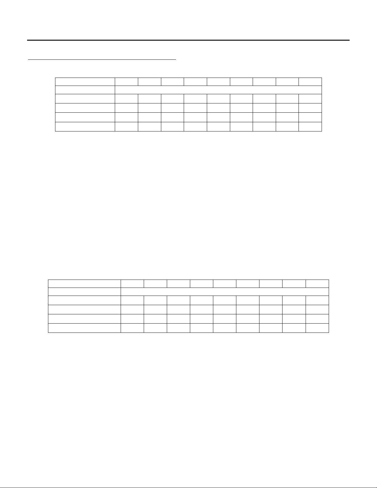
Suggested Re-lubrication Schedule (Months)* for Dodge Ball Bearing Pillow Block
* Suggested initial greasing interval. . If safety permits, re-lubricate while running until some purging
occurs at seals. Adjust lubrication frequency depending on condition of purged grease. Hours of
operation, temperature and surrounding conditions will affect the re-lubrication frequency required. For 24
hour operation double the lubrication frequency.
Lubricate with a multipurpose NLGI No. 2 or No. 3 ball bearing grease having rust inhibitors, antioxidant
additives and a minimum viscosity of 500 SSU at 100°F (38°C). Some examples of grease having these
properties are:
Shell Alvania RL 2
Mobil Mobilith SHC220
Exxon Ronex MP
Lubricate bearings prior to extended shutdown or storage and rotate shaft monthly to aid corrosion
protection.
Suggested Re-lubrication Schedule (Months)* for Dodge Spherical Roller Bearing - Solid Pillow
Block
* Suggested initial greasing interval. If safety permits, re-lubricate while running until some purging occurs
at seals. Adjust lubrication frequency depending on condition of purged grease. Hours of operation,
temperature and surrounding conditions will affect the re-lubrication frequency required. For 24 hour
operation double the lubrication frequency.
IOM-26 29 of 33 Oct 12 R4
Page 30

A HE, DE & RE MANUAL
Speed (RPM)
500
750
1000
1500
2000
2500
3000
3500
4000
** oz.
Shaft DIA.
1 7/16” – 1 15/
16”
6
4 1/2 4 4
3 1/2
2 1/2
2 1/2 1 1
0.05
2 3/16” – 2 11/16”
5
4 1/2
4
2 1/2
2 1/2
1 1/2 1/2 1/4 1/4
0.75
2 15/16” – 3 15/16”
4 1/2
4
3 1/2
2 1/2
1 1/2
1 1/2
2.00
4 7/16” – 4 15/16”
4 4 2 1/2
1
1
/
2
4.00
5 7/16” – 5 15/16”
4
2 1/2
1 1/2 1
7.00
Lubricate with a multipurpose roller bearing NLGI No. 2 having rust inhibitors and antioxidant additives, and
a minimum oil viscosity of 500 SSU at 100°F. Some examples of grease having these properties are:
Shell Alvania No. 2
Mobil Mobilith AW2
Mobilith SHC100
Texaco Premium RB2
American Rykon Premium 2
Lubricate bearings prior to extended shutdown or storage and rotate shaft monthly to aid corrosion
protection.
Suggested Re-lubrication Schedule (Months)* for Dodge Spherical Roller Bearing – Split Pillow
Blocks
* Suggested initial greasing interval. Remove bearing cap and observe condition of used grease. Adjust
lubrication frequency as needed. Hours of operation, temperature and surrounding conditions will affect
the re-lubrication frequency required. Clean and repack bearing annually. Remove old grease, pack
bearing full and fill housing reservoirs on both sides of bearing to bottom of shaft. For 24 hour operation
double the lubrication frequency.
** Grease to be added at each interval.
Lubricate with a multipurpose roller bearing NLGI No. 2 having rust inhibitors and antioxidant additives, and
a minimum oil viscosity of 500 SSU at 100°F. Some examples of grease having these properties are:
Shell Alvania No. 2
Mobil Mobilith AW2
Mobilith SHC100
Texaco Premium RB2
American Rykon Premium 2
Lubricate bearings prior to extended shutdown or storage and rotate shaft monthly to aid corrosion
protection.
Static Oil Lubrication
Use only highest quality mineral oil with a minimum viscosity of 100 SSU at the oil’s operating temperature.
The oil’s operating temperature is approximately 10°F greater than the bearing’s housing. SAE values
having this viscosity at the following operating temperature are:
150° - SAE 20 160° - SAE 30 180° - SAE 40
Static oil level should be at the center of the lower-most roller (do not overfill).
Complete lubrication change should be made annually.
IOM-26 30 of 33 Oct 12 R4
Page 31

A HE, DE & RE MANUAL
Hours Service
Per Day
Up to 7.5 HP
Up to 5.6 kW
10 to 40 HP
7.5 to 29.8 kW
Over 40 HP
Over 29.8 kW
Less than 12
5 Years
3 Years
1.5 Years
More than 12
2 Years
1 Year
9 Months
MOTOR LUBRICATION
Refer to motor manufacturer for lubrication recommendations.
On motors having grease drain plugs, remove the plugs and operate the motor for 15 minutes before
replacing plugs. DO NOT OVER GREASE.
RECOMMENDED MOTOR LUBRICATION INTERVALS
NOTE: Motors that run in severe conditions should be greased as specified by the motor manufacturer.
GAS MANIFOLD
It is recommended that at least once each year the safety devices should be checked. Follow operational
check at detailed in this manual.
The Safety Shut Off Valves must be tested on at least an annual basis or as per the manufacturer’s
recommendations which ever is less.
Regulators with vent terminals must have yearly cleaning of the screen.
IOM-26 31 of 33 Oct 12 R4
Page 32
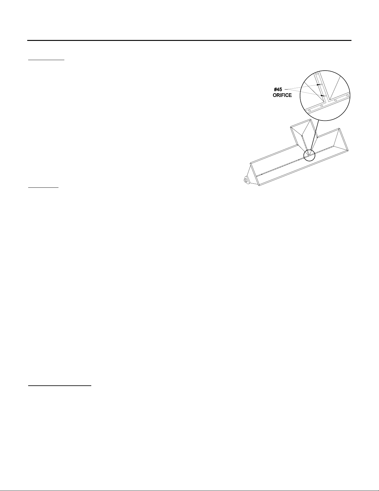
A HE, DE & RE MANUAL
BURNERS
It is recommended that the burner be inspected once each year.
Remove any scale that may have accumulated on the burner plates.
Ensure that the holes on the burner plates and gas orifices are
completely clear of foreign material. The first 2 orifices on the tee
casting as shown are #45, all others casting orifices are #42.
FILTERS
Filter-changing intervals can be based on the pressure drop across the filter or by calendar scheduling or
visual inspection. Scheduled intervals should be between one and six months, depending on the pollutant
loading from indoor and outdoor air. More-frequent changes may be required during the economizer
season.
Units that operate with high levels of outside air should have filters removed (or moved to winter
filter location if available) during the winter months in areas that have heavy frost or snow.
Plugged or excessively dirty filters can cause damage to the equipment. See submittal record for filter
quantities, sizes and types. Use same size and type for replacement.
A. High Velocity Permanent:
It is important that the filters be checked and cleaned regularly during the period immediately
following installation, in order to determine the best service interval. To clean, rinse with water.
Shake off excess water and re-install. These filters do not require an oil adhesive.
B. Pleated Throwaway and/or Replaceable Media (Cartridge, Bag):
Replacement filters can be obtained from any Engineered Air representative.
In some applications the used filters/media may contain chemical or biological hazards. All local, regional
and national regulations for safety and disposal should always be followed.
VFD ENCLOSURE
Filters may be located on the air inlet of VFD enclosures. Filter-changing intervals can be based on
calendar scheduling or visual inspection. Scheduled intervals should be between one and six months,
depending on the pollutant loading in the enclosure area.
IOM-26 32 of 33 Oct 12 R4
Page 33
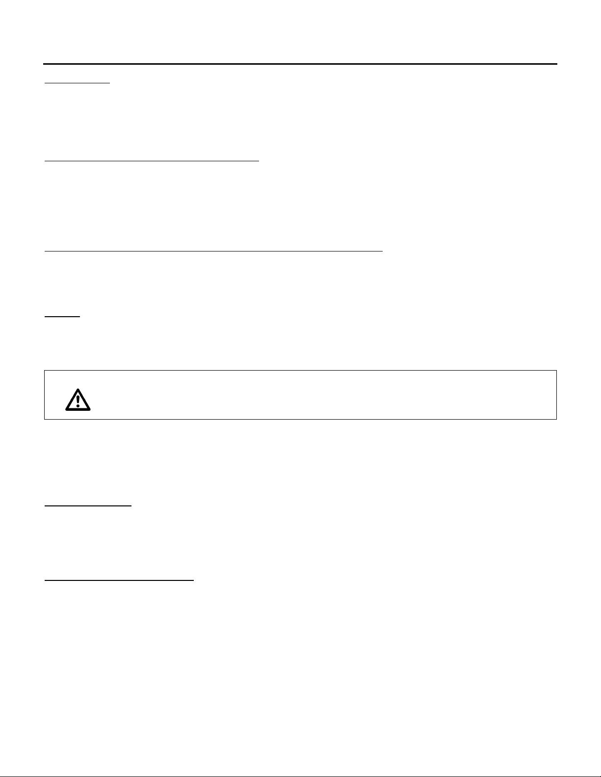
A HE, DE & RE MANUAL
Warning:
Dirty coils can be a cause of poor air quality. Failure to maintain clean coils
can cause injury or death, damage to the equipment, property damage or
system operational problems. Moisture carry over can result from dirty coils.
CONTROLS
Annually clean and recalibrate all controls, check for proper operation, and repair or replace any faulty
controls. Check all damper hardware settings every three months. Replace blown fuses with equivalent
size and type fuse. Failure to do so can result in damage to the unit.
CONTROL ENCLOSURE VENTILATION
Control enclosures are often ventilated in summer to provide component cooling. A manually adjustable
slide damper is provided for adjustment and seasonal shut off. The slide damper should be closed for
winter operation and opened for summer operation.
OUTDOOR AIR INTAKES, MIXING SECTIONS AND DAMPERS
Outdoor air intakes, screens, and adjacent areas shall be checked semi-annually for cleanliness, integrity
and proper operation. Adjust dampers where required.
COILS
Inspect coils and drain pans for cleanliness and biological growth once per year during the cooling season
or more often as required.
The external surface of finned coils can be cleaned using a low pressure water spray and a brush. Coil
fins are easily damaged. Do not use high pressure steam or water to clean coils; it will permanently
damage the coil. When using cleaning additives or solutions they must be compatible with the coil
materials or coatings. Use a fin comb to straighten any damaged or bent fins.
Coil Winterization:
Water coils that are not in use must be protected from freezing. Coils should be drained and blown out
with compressed air and then filled and drained several times with appropriate strength pre-mixed inhibited
HVAC glycol or other suitable fluid. Do not use propylene glycol with CPVC piping.
ULTRAVIOLET SCANNERS
The viewing area of the scanner must be kept clean. Even a small amount of contamination will reduce the
flame signal reaching the detector by a measurable amount. Wipe the viewing area routinely using a soft
cloth dampened with concentrated detergent.
For additional information refer to the uv scanner manufacturers’ literature.
IOM-26 33 of 33 Oct 12 R4
 Loading...