

Page 1
UNIT MODEL NO. _________________
UNIT SERIAL NO. _________________
SERVICED BY: ___________________
TEL. NO: ________________________
CANADIAN
HEAD OFFICE
AND FACTORY
USA
HEAD OFFICE
AND FACTORY
CANADIAN
EASTERN FACTORY
1401 HASTINGS CRES. SE
CALGARY, ALBERTA
T2G 4C8
Ph: (403) 287-4774
Fx: 888-364-2727
32050 W. 83rd STREET
DESOTO, KANSAS
66018
Ph: (913) 583-3181
Fx: (913) 583-1406
1175 TWINNEY DRIVE
NEWMARKET, ONTARIO
L3Y 5V7
Ph: (905) 898-1114
Fx: (905) 898-7244
SALES OFFICES ACROSS CANADA AND USA
Retain instructions with unit and maintain in a legible condition.
Please give model number and serial number when contacting
Engineered Air for information and/or parts.
A
INSTALLATION, OPERATION
AND MAINTENANCE MANUAL
FOR
C-TRAC3
COOLING CONTROLLER
Jan 13 R5
www.engineeredair.com
Page 2
A
Warning:
This unit is connected to high voltages. Electrical shock or death could occur if
instructions are not followed. This equipment contains moving parts that may start
unexpectedly. All work should be performed by a qualified technician. Always
disconnect and lock out power before servicing. DO NOT bypass any interlock or
safety switches under any circumstances.
C-TRAC3
If any errors or omissions are noted please contact Engineered Air – Calgary Service at
(403) 287-2590 or Fax (403) 287-4799 or email [email protected].
To ensure warranty is honored, only a qualified HVAC service person, who has received training on the
C-TRAC3, should be employed for service and troubleshooting. If further information is required please
contact the nearest Engineered Air office.
Under no conditions (except for temporary copying) should the unit function description be removed from
the unit. There are two copies provided with the unit. One is in an envelope for copying, then return it to
the unit or store in a safe place. The other is attached to the control panel door and should never be
removed. If a copy of the function for a particular unit is needed, contact Engineered Air with the unit
serial number, C-TRAC3 model number (ex model C-TRAC3.3.1) and the C-TRAC3’s program number noted
near the top right corner of the controller. The program number should also be noted on the electrical
drawing.
2 of 21 Jan 13 R5
Page 3

A C-TRAC3
Table of Contents
INTRODUCTION ................................................................................................................................................................ 5
STARTUP AND SHUT DOWN ............................................................................................................................................. 5
SERVICE SWITCH ............................................................................................................................................................... 5
TEMPERATURE CONTROL ................................................................................................................................................. 6
BASE SETPOINT ................................................................................................................................................................. 6
SETPOINT RESET ............................................................................................................................................................... 6
SETPOINT LIMITS .............................................................................................................................................................. 6
MODES OF OPERATION .................................................................................................................................................... 6
SENSOR #2 ........................................................................................................................................................................ 7
MEASURING TEMPERATURE AND SETPOINT ................................................................................................................... 7
OPERATION ....................................................................................................................................................................... 7
AMBIENT SENSING ............................................................................................................................................................ 8
BLOWER CONTROL ........................................................................................................................................................... 8
ECONOMIZER MODE ........................................................................................................................................................ 8
MINIMUM POSITION ........................................................................................................................................................ 9
Ambient Compensation .................................................................................................................................................. 10
HEATING MODE .............................................................................................................................................................. 10
COOLING MODE .............................................................................................................................................................. 10
DUAL MODE .................................................................................................................................................................... 10
OCCUPIED/UNOCCUPIED ................................................................................................................................................ 11
INDICATION AND DIAGNOSTIC LIGHTS ........................................................................................................................... 11
LOW LIMIT ...................................................................................................................................................................... 13
VARIABLE AIR VOLUME .................................................................................................................................................. 13
WIRING ........................................................................................................................................................................... 14
EMS Wiring ..................................................................................................................................................................... 15
TROUBLE SHOOTING ...................................................................................................................................................... 15
BASIC (MULTIMETER) ..................................................................................................................................................... 15
DIP Switches (C-TRAC 3.2 and higher) ............................................................................................................................ 15
SIMULATING A HEAT/COOL CALL ................................................................................................................................... 16
ENCHANCED (COMPUTER) ............................................................................................................................................. 16
Calibration ...................................................................................................................................................................... 17
SENSOR TABLES .............................................................................................................................................................. 18
SERVICE NOTES ............................................................................................................................................................... 19
3 of 21 Jan 13 R5
Page 4
A C-TRAC3
4 of 21 Jan 13 R5
Page 5
A C-TRAC3
The C-TRAC3 is designed to control Engineered Air equipment only. It is not designed to simulate or
copy other controllers on the market today, nor can it be modified to do so.
CAUTION:
All of the remote wiring must be complete and functional before attempting to start
the unit.
CAUTION:
It is important that the service technician understands the C-TRAC3 is a configurable
controller. While the terminal designation remains the same, the operation of the
terminal is dependent on the required function, and may differ from unit to unit.
The C-TRAC3 is not field programmable. If the C-TRAC3 program becomes damaged or corrupted, it
must be replaced or returned to Engineered Air for re-programming.
INTRODUCTION
The CTRAC-3 is designed to control the cooling, heating, mixing economizer and fan(s). Additionally, it
allows for independent control of other types of equipment operations such as multi-zone and
dehumidification.
The CTRAC-3 requires a 24Vac grounded power supply. The fuse is located on the back of the control, and
has a rating of 800mA (slow blow). Fuse failure can be checked by having 24Vac across terminals H and N,
but the small green light on the face of the C-TRAC3 is not illuminated. There should also be no Vdc
reading across V and Z.
This information in this manual should be used in conjunction with the unit function sheet(s) and the
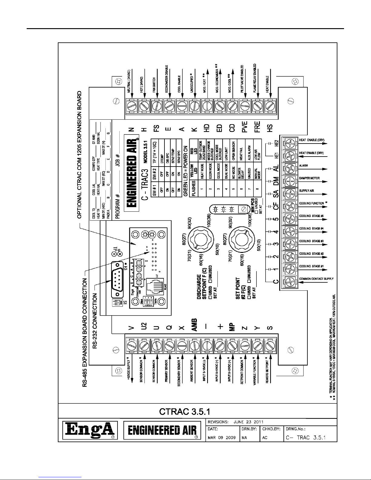
terminal designation list that accompanied the equipment.
The C-TRAC3 configuration program number is noted on the face of the C-TRAC3. This number is
important when contacting the factory about the unit operation, or for replacement parts. This number
should accompany the unit serial and tag number, and model number.
STARTUP AND SHUT DOWN
Startup and shutdown should always be accomplished by the use of the remote start contacts and/or
switches, or the unit on/off switch or an EMS control signal. This will allow the C-TRAC3 to disable unit
operation in sequence, protecting the unit components from damage.
SERVICE SWITCH
The service switch, located in the main electrical control panel, is designed for service and maintenance
use only, and should not be used to regularly enable or disable normal operation. Once the unit has
5 of 21 Jan 13 R5
Page 6

A C-TRAC3
Additional details regarding startup and shutdown are noted in the unit function and in the Installation,
Operation and Maintenance manual.
completely shut down, turn the main disconnect switch off prior to attempting any service or
maintenance.
TEMPERATURE CONTROL
BASE SETPOINT
The C-TRAC3 is designed to be a discharge air temperature controller. The base discharge air temperature
setpoint is typically set from the setpoint 1 control knob located on the face of the
C-TRAC3. Optionally, this setpoint may be replaced by a remote mounted potentiometer, directly set from
a remote BMS signal (0-10Vdc), preset from a computer, or commanded from an EMS signal. If not used,
set this knob to maximum (fully clockwise), as noted on the face of the C-TRAC3.
The C-TRAC3 has the ability to perform 2 independent operations at the same time, such as a
dehumidification system (pre-cool and reheat) or a multizone system (hot deck, and cold deck). These
types of systems normally incorporate both face-mounted setpoint dials, but the optional setpoints noted
above can still apply to both or either setpoint. As above, if setpoint 2 is not used, set to maximum, as
indicated on the face of the C-TRAC3.
SETPOINT RESET
The base discharge air temperature is normally modified from a remote signal to maintain the desired
temperature of the supplied space. This is called reset. The C-TRAC3 discharge temperature can be reset
from a variety of sources such as ambient air temperature, modulating or staged room thermostats, return
air temperature, or a BMS signal (0-10Vdc).
The resulting change in the discharge temperature setpoint from reset is the actual, or calculated,
discharge air temperature setpoint. This is normally referred to as the SPC.
SETPOINT LIMITS
The discharge air setpoint range is set, and limited to, a specified temperature range programmed prior to
shipment. For example, if the minimum discharge temperature is programmed at 60°F, then that is the
minimum possible temperature setting. Even though the setpoint dial may go as low as 50°F, the
calculated, or actual, setpoint can never go below 60°F.
MODES OF OPERATION
The C-TRAC3 has 3 distinct sequential modes of operation: heating, economizer and cooling. Depending
on ambient conditions the C-TRAC3 may start in any of the three modes. Mode change time is five
minutes (six minutes from heat to mechanical cooling if there is no economizer). If the C-TRAC3 is unable
6 of 21 Jan 13 R5
Page 7
A C-TRAC3
Mode
Terminal
Operation
Heat
HS
Heating is allowed with 24Vac at the terminal.
Economizer
E
Economizer is disabled to minimum with 24Vac.
Cool
A
Cooling is allowed with 24Vac at the terminal.
CAUTION:
All of the remote wiring must be complete and functional before attempting to start
the unit.
to satisfy the SPC in its present mode and the discharge temperature slips outside of the discharge
temperature dead band then it will begin timing for a mode change. Once the timing is completed, it can
change modes. If the timer is active and the discharge temperature slides back into the dead band, the
mode change timer is reset. If the current operating mode becomes disabled the C-TRAC3 will immediately
move into the next mode. A preprogrammed option can disable the unit operation if no modes are
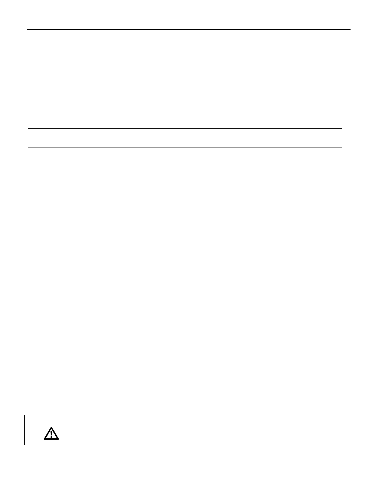
available. The table below indicates which 24Vac input terminal can enable or disable its corresponding
mode.
Table 1
The C-TRAC3 will not always be able to exactly maintain the SPC. Enabling a cooling compressor, for
example, may cause the discharge temperature to fall below the SPC. When the compressor is disabled
the temperature may rise above the setpoint. On average, however, the discharge temperature will
closely match the SPC.
The C-TRAC3 controls to a +/-2°F dead band of the SPC when in heating and economizer mode. The
cooling dead band is based on the dry bulb temperature drop of each stage of mechanical cooling.
SENSOR #2
The C-TRAC3 is has the option of using, and controlling to, two sensors. Some equipment may incorporate
2 discharge air sensors for improved temperature control. Multi-zone equipment use sensor #1 for the
hot deck, and sensor #2 for the cold deck. Dehumidification equipment use sensor #1 for the reheat
(leaving) section, and sensor #2 for the pre-cool section.
MEASURING TEMPERATURE AND SETPOINT
The calculated setpoint (SPC) and the actual temperature can be monitored using a DC voltmeter and the
temperature test points and a DIP switch block mounted on the face of the C-TRAC3 (located near the
RS232 serial connection). Note that the calculated setpoint includes any resets to the setpoint. Refer to
Table 4 on page 14.
OPERATION
As the C-TRAC3 is configurable and will vary in its operation unit to unit, it is imperative that the unit
function, terminal designation sheet and wiring diagram be reviewed to understand how the control is
operating for each particular application.
7 of 21 Jan 13 R5
Page 8

A C-TRAC3
Control of occupied and unoccupied time may be accomplished with an EMS controller. If used, and
enabled by the SMC programming software, the 24Vac input into terminal K is not required.
AMBIENT SENSING
The C-TRAC3 constantly monitors the ambient temperature using an Engineered Air TE6000EA3 sensor. On
initial start up the C-TRAC3 pre-determines which mode to start in: heating, cooling, or economizer. The
load requirements, ambient temperature and digital inputs determine which mode the C-TRAC3 can start
in. Note that some applications will involve dual modes, such as dehumidification and multi-zone
equipment.
The C-TRAC3 must have an ambient sensor installed to operate, or it will lockout on ‘open sensor’ failure.
BLOWER CONTROL
When 24Vac is applied to terminal FS the C-TRAC3 is considered to be in occupied mode. After a time
delay, that allows the damper actuators to respond, the blower(s) will be enabled by closing the output
contact between terminals C and SA. The time delay is variable depending on the equipment and the
function.
Fan start timing will vary depending on the unit configuration. Make up air equipment has a base delay
time of 90 seconds, while equipment with mixing dampers have a 10 second base delay time. Additionally,
there may be delays for morning warm up, cool down, and pump down, which may vary depending on the
ambient and discharge air temperature. Always refer to the unit function for specific application time
values. The fan delay off time can vary from 10s to 2.5 minutes.
ECONOMIZER MODE
When in economizer mode the C-TRAC3 will mix the warm return air with the cool outside air to try and
achieve the required discharge SPC. The C-TRAC3 will modulate the mixing dampers (return, outside and if
equipped, exhaust) from fully open to the minimum position setting (expressed as a percentage of outside
air).
The C-TRAC3 has 2 independent outputs for damper control. One is a 24Vac output from terminal DM for
on/off control or a 2 position damper actuator. The other is a modulating Vdc output from terminal ED for
modulating (economizer) actuator control. Flat mixing boxes are set to output a 0-7Vdc range, while angle
mixing boxes use a 0-10Vdc range.
The C-TRAC3 will drive the actuator to minimum position when in heating mode. Optionally, the
C-TRAC3 can be programmed to either drive the damper actuator to minimum position when in cooling
mode or continue to modulate to 100% outside air. If set to modulate, the dampers will decrease the
amount of outside air as the mechanical cooling is enabled to ensure that there is sufficient startup load to
avoid damaging the compressor. Once the compressor has started, the dampers will slowly modulate
open, as required.
8 of 21 Jan 13 R5
Page 9

A C-TRAC3
If input terminal E is powered (24Vac), the modulating output signal will drop to the minimum outside air
position setting. An optional enthalpy control is normally connected to this terminal.
Unoccupied mode will disable the mixing dampers to 100% return air.
MINIMUM POSITION
The normal setting for the minimum amount of outside air is 15%, although there are many situations
where this number could vary substantially. Refer to the unit function sheet to determine the required
amount.
The mixed air minimum position setpoint is typically adjusted at the C-TRAC3 using the face mounted
minimum position potentiometer; however a variety of methods could be employed. Input terminal MP
may be used to set the minimum position from a remote 0-10Vdc signal (10Vdc = 100% outside air). The
minimum position can also be programmed into the C-TRAC3 through the RS232 communication port from
a computer or directly controlled from an EMS signal. If the minimum position potentiometer is not used
it should be set to zero (turned fully CCW) as it remains in the hardware control circuit.
The mixed air minimum position may overridden from another device, such as a building static pressure
sensor or CO sensor. Refer to the unit function and wiring diagram to clarify. If used, this is normally a
“flow through” device that would input to the MP terminal on the C-TRAC3 first. The C-TRAC3 would then
output the appropriate signal to the damper actuator(s), rather than the minimum position signal directly
feeding into the damper actuator.
Variable Frequency Drives
If the equipment is employing variable frequency drives to control the fan speed (and program options are
selected), a feedback signal of actual speed (10Vdc = 60Hz) is connected to the C-TRAC3. This is to ensure
the airflow is adequate to correctly operate and safeguard the equipment.
As the total air volume drops when the VFD speed decreases, the amount of minimum outside air also
decreases. To compensate for this, the C-TRAC3 will automatically increase the minimum outside air
signal to the damper actuator(s) to allow for more outside air.
Under low air volume conditions the C-TRAC3 will limit the maximum amount of heating and cooling
output for improved temperature control and to safeguard the equipment. This is referred to as ‘load
shedding’. This feature has been removed in versions 3.6 and later.
Refer to the variable air volume section of this manual for additional information.
Mixed Air Low Limit Override
To avoid low limit failure, if the discharge air temperature approaches the low limit setpoint (typically
40°F) the C-TRAC3 will try and keep the unit operational by decreasing the minimum outside air position
down to ½ of its setpoint.
9 of 21 Jan 13 R5
Page 10

A C-TRAC3
Ambient Compensation
Makeup air equipment normally uses a 2 position damper actuator. Equipment can be ordered with an
Ambient Compensation Package. Among other things, this package uses a modulating outside air damper
actuator. The modulating economizer output (ED) will control the actuator and vary the output signal
depending on the ambient temperature. As the ambient temperature falls, the output will decrease
proportionally, adding static pressure drop across the dampers and effectively reducing the outside air
volume. This compensates for the thermal expansion of the air as it passes over the heat exchanger.
HEATING MODE
Heating is allowed to operate if terminal HS is powered (24Vac). The heating is only activated when the CTRAC3 is in heat or dual mode. The C-TRAC3 has a set of contacts (terminals HE1 and HE2) that will close
to enable a heating source, as well as a modulating (0-10Vdc typically) output from terminal HD to control
an independent heating controller, SCR, or water/steam valve. Typically this output will drive one of the
Engineered Air heating controllers (G-TRAC, DJM, H-TRAC etc). Refer to the appropriate manual for
additional information on these controls.
COOLING MODE
Cooling mode is allowed if terminal A is powered (24Vac) and the ambient temperature exceeds the
minimum, pre-programmed low ambient setpoint. The cooling is only activated when the C-TRAC3 is in
cool or dual mode. The C-TRAC3 has 5 output contacts (1 to 5) to enable mechanical cooling stages.
Additionally, a modulating (0-10Vdc typical) output is available from terminal CD for control of a
modulating style of compressor or cooling valve actuator.
Terminal CF is an ambient based cooling output (24Vac). If the first cooling stage is enabled, and the
ambient temperature is above the pre-programmed setpoint, this contact will close. Typical applications
for this would be for an ambient based condenser fan or compressor.
Compressor inter-stage, and minimum on/off times range from 4 to 8 minutes depending on operating
conditions. When the C-TRAC3 first enters cooling mode the first compressor minimum delay is 2 ½
minutes, with the second compressor capable of starting 20 seconds later. These short compressor start
times occur only once whenever the C-TRAC3 initially enters the cooling mode.
Terminal AMB is wired to an externally mounted ambient sensor (Engineered Air TE6000-EA3). The
C-TRAC3 uses this sensor to perform multiple functions, such as low ambient compressor lockout, high
ambient set back, and mode control.
DUAL MODE
Dual control mode allows the cooling or economizer to operate at the same time as the heating. These
are for dehumidification and multi-zone equipment applications.
10 of 21 Jan 13 R5
Page 11

A C-TRAC3
# of Flashes
Yellow LED
Red LED
1
Heat Mode
Temperature outside dead band
2
Economizer Mode
Mode change blocked
3
Cool Mode
Cooling mode blocked
4
Dual Mode
Low Limit
5
No Mode
Open Sensor
6
Blower Delay
Heat Fail
7
Unused
Auxiliary Alarm
8
Manual Control Mode
Low Air Flow
OCCUPIED/UNOCCUPIED
The C-TRAC3 is capable of a wide variety of control options for occupied/unoccupied control. Read the
unit function and wiring diagram carefully to understand the particular application. The mixing dampers
will set to 100% return air. This option is not available on make up air equipment.
The C-TRAC3 is capable of unoccupied heating and unoccupied cooling. Additionally, unoccupied fan
control may be continuous or intermittent.
An independent unoccupied setback thermostat is required if the unit does not have any method of
temperature reset. Normally the modulating room reset sensor is used, with the unoccupied setback
temperature pre-programmed. Systems using a remote 0-10Vdc discharge setpoint will trigger
unoccupied heating with an input signal greater than 6Vdc.
Switching input power (24Vac) from terminal ‘FS’ (fan switch or occupied mode) to terminal ‘K’ (knight or
unoccupied mode) puts the equipment into unoccupied mode. An EMS controller, connected to the CTRAC3 may enable occupied and unoccupied modes without the need of the FS and K input terminals.
INDICATION AND DIAGNOSTIC LIGHTS
On the face of the C-TRAC3 are 3 small LED lights, coloured green, yellow, and red. The green light is to
indicate the C-TRAC3 is powered and ready for operation. If power (24Vac) is applied to terminals H and
N, and the light is not on, the C-TRAC3 may be faulty and/or the fuse is blown. The yellow light indicates
mode and blower delay. The red light indicates problems and failures.
The yellow and red lights will flash on and off a number of times for indication. A noticeable pause occurs
between sets of flashes to avoid confusion. It is not the rate of flashes, but the number of flashes. Refer
to the table listed on the face of the C-TRAC3 or the table below.
Table 2
Heat Mode flashes when the C-TRAC3 is in this mode. The HE1 and HE2 contacts will be closed and the
modulating output will react based on the heating demand. It is possible to be in heat mode, with no
heating occurring.
11 of 21 Jan 13 R5
Page 12

A C-TRAC3
Economizer Mode flashes when the C-TRAC3 is in this mode. The modulating output from terminal ED can
rise above the minimum position to modulate the mixing dampers and maintain the required discharge air
temperature.
Cooling Mode indicates the mechanical cooling staged output contacts are available to begin enabling the
5 stages of mechanical cooling. All stages have minimum run time, minimum off time, and inter-stage
timing. As well, there may be an optional choice of a modulating cooling output signal if a modulating
compressor or other device such as a modulating chilled water coil is desired.
Dual Mode is a function used on equipment where the heating mode and the cooling or economizer
modes operate at the same time with independent set points.
Ex: multi-zone applications, or de-humidification functions.
No Mode will flash when the C-TRAC3 is not allowed to run the heating (HS not powered), cooling (A not
powered) or economizer (E powered). This generally occurs because of external controls, ambient
lockout, flame failure, etc. The C-TRAC3 can be preprogrammed to eliminate certain modes. For example
a makeup air unit does not have an economizer mode.
Blower Delay is to indicate the blower is preparing to start, but has internal timers to allow for the
dampers to open, or to warm up the heat exchanger.
Manual Control Mode indicates the C-TRAC3 is being controlled by SMC software directly.
Compressor Disabled refers to the mechanical cooling being disabled by the SMC software.
Temperature outside dead band means the temperature is no longer at setpoint and the C-TRAC3 is
attempting to resolve the error.
Mode Change Blocked indicates the C-TRAC3 wishes to change modes (ex economizer to cooling) but the
mode is blocked due to an external signal control, or no such mode exists.
Cooling Mode Blocked indicates the mechanical cooling mode is disabled from either low ambient
temperatures or terminal A not being powered.
Low Limit will flash when the unit has failed because of low discharge temperature, usually associated
with flame failure.
Open Sensor will blink and disable unit operation if the discharge or ambient sensor has failed (open
resistance). This is an optional setting, which may include sensor #2.
Heat Fail will flash if the gas fired heater has failed to ignite. The C-TRAC3 monitors the burner operation
with terminals PVE (pilot valve) and FRE (flame relay), and can be configured to shut down and lock out
the system on a flame failure. Some heaters may be configured for automatic re-light up to 3x before the
C-TRAC3 will go into heat fail. Electric heaters have a feedback, after the safety switches (high limits, air
switch and door switch), to terminal PVE which must prove within 1 minute, after the fan has started.
12 of 21 Jan 13 R5
Page 13

A C-TRAC3
Auxiliary Alarm indicates a failure of an external binary input into one of the optional programmable CTRAC3 terminals. Refer to the unit function sheet and wiring diagram to determine what type of input and
which terminal. Typically, this input would be a filter switch or a current sensor.
Low Air Flow is a noted indication of either the VFD operating at too low of a speed, or an open air flow
switch (if used). Refer to the unit function sheet and wiring diagram to determine which type and
terminal.
LOW LIMIT
The C-TRAC3 control will have low limit (freeze) protection included as a standard option. To reset the
control after a low limit trip the C-TRAC3 must have the power removed and restored to terminals H and
N. This is usually done by turning the unit off at the service switch located inside of the control cabinet. A
computer or EMS can also command the C-TRAC3 to reset the air handler from a low limit alarm.
On initial start-up the C-TRAC3 will bypass low limit sensing for a pre-set amount of time, determined by
the size and type of heat exchanger, the ambient temperature and the discharge air sensor temperature.
The bypass timer is also reset if the minimum position is increased by more than 15% or the VFD feedback
signal increases by more than 10%. This is to avoid nuisance low limit tripping while the heat exchanger is
recovering from a sudden increase in air. The anti-nuisance time is set to 30 seconds for all applications,
and will automatically reset itself if the temperature rises above the low limit setpoint.
If the discharge air temperature approaches the low limit setpoint on equipment incorporating an
economizer mixing box function, the C-TRAC3 will automatically decrease the minimum position down to
½ of its original setting.
VARIABLE AIR VOLUME
Variable air volume and 2 speed systems change the amount of air being moved by the system using a
variety of means. The C-TRAC3 can accept the feedback signal of a variable frequency drive, connected to
input terminals on the C-TRAC3 (0-10Vdc). Refer to the wiring diagram to determine which terminals are
used. The C-TRAC3 is capable of adjusting the temperature control according to the change in the air
volume signal. For example, on a significant decrease in airflow, the C-TRAC3 will force unnecessary
compressors off to avoid possible damage to the refrigeration components. Reduced airflow would also
limit the number of cooling stages that could operate. A sudden volume change will also affect the heating
control. The heating ramp responds more quickly to increase the heating output on an increase in air
volume. Additionally, the internal low limit bypass time is reset on a sudden increase in air volume.
On units equipped with mixing dampers, the C-TRAC3 can increase the minimum position during a
decrease in air volume. This is to maintain the minimum required amount of outside air. For example, an
RTU delivering 10,000cfm at 10% minimum outside air should be moving 9000cfm return air and 1000cfm
outside air. If the VFD was reduced to 50% volume we would be delivering 4500cfm return air and 500cfm
outside air = 5000cfm total. The minimum fresh air required is still 1000cfm. To account for this, the
damper minimum position will be increased to allow 1000cfm of outside air and 4000cfm of return air.
13 of 21 Jan 13 R5
Page 14
A C-TRAC3
CAUTION:
Adding a variable air volume system to equipment originally designed with
constant air flow will void warranty, unless approved and recorded by Engineered
Air.
This is a calculated increase meant to compensate for a reduction in total airflow, not a measured actual
value.
External controls are required to disable the mechanical cooling and heating if the VFD has been switched
to bypass mode, due to VFD failure.
If the C-TRAC3 is configured for variable airflow systems, the minimum position pot is factory sealed at the
fully counter-clockwise position, as the input will interfere with the VFD minimum speed setting.
WIRING
The C-TRAC3 terminals H and N require a minimum 24 Vac, 40 VA class 2 power supply that does not need
to be isolated from the rest of the systems components. The C-TRAC3 incorporates an internal ½ wave
rectified power supply that has the DC common virtually the same as the AC’s neutral supply (within
0.05Vdc).
Terminal N should be wired to the common of the same source supplying power to terminals E, A, and K.
All remote wiring attached to terminals Q, U, X, Y, V, Z, + and - should be installed in a clean (no electrical
noise) environment. Wire size should be a minimum of 24ga. twisted pair to reduce electrical noise
(shielded wire is recommended). For longer runs (over 50 ft. eq. length), the use of a minimum
20 gauge-shielded wire is recommended. The shield should be grounded at the unit end only, with the
other end taped.
It is important to ensure correct polarity when wiring into the system.
The modulating output signals from the C-TRAC3 can be programmed for other voltage ranges if needed
for operating other controls. The minimum load resistance is 500 Ohms. The possible variable voltage
ramps are:
0 – 10 VDC
0 – 7 VDC
0 – 5 VDC
0 – 2 VDC
As noted, these are configured values and the selected value is noted in the unit function sheet.
If the BMS input terminals (+ and -) are included as part of the unit function and are not field wired, the
signal is considered as being zero, therefore the control will operate as described when this signal is low
(ex maximum cooling).
14 of 21 Jan 13 R5
Page 15

A C-TRAC3
Vdc
0.5
1.0
1.3
1.5
1.8
2.1
2.4
2.7
2.9
3.2
°C
5
10
13
15
18
21
24
27
29
32
°F
40
50
55
60
65
70
75
80
85
90
EMS Wiring
The RS-485 communication cable to the C-TRAC3 is 24awg shielded twisted pair (STP) with a shunt
capacitance of 16pF per foot and 100 ohm characteristic impedance. Category 5 cable can be used as
defined by the EIA/TIA/ANSI 568 specification.
TROUBLE SHOOTING
The C-TRAC3 is designed to simplify service and troubleshooting. Most equipment failures and problems
occur due to sources external to the C-TRAC3, and can easily be traced with a digital multimeter.
Advanced troubleshooting may require the use of a computer.
BASIC (MULTIMETER)
The equipment has a function and terminal list attached to the electrical panel door. These explain how
the equipment is designed to operate. This information, along with the flashing patterns from the C-TRAC3
status lights and multimeter sensor and setpoint readings should allow for a majority of troubleshooting to
effectively take place.
Do not jumper or open circuit sensors. If necessary it is possible to substitute fixed or variable resistors in
place of the sensors for test purposes. Refer to the table later in this document for various sensor values at
various temperatures.
There is a test point and DIP switch block near the RS-232 connection for checking actual temperatures
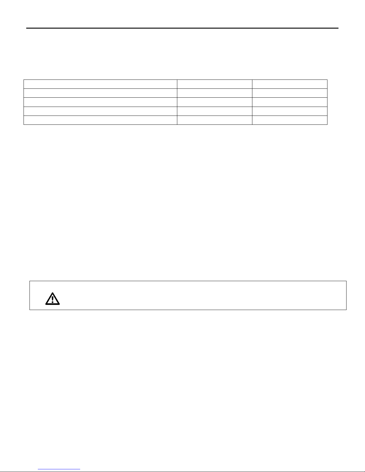
and setpoints. Refer to the DIP switch settings to determine which of the 4 possible variables are being
read. Referenced to ground, measure a DC voltage that relates to temperature in °C. Refer to Table 3 and
Table 4 below.
Table 3
Note the above actual temperature reading is the value at the Engineered Air sensor or setpoint. If there is
a building management system measuring temperature, its sensor should be located within one inch of
the Engineered Air sensor.
DIP Switches (C-TRAC 3.2 and higher)
A DIP switch block located to the left of the RS-232 connector will switch the multimeter test point to read
a variety of temperatures and setpoints. See the table below. Note that early versions of the
C-TRAC3 had selection jumpers.
15 of 21 Jan 13 R5
Page 16
A C-TRAC3
Voltage Readout Function
DIP Switch #1
DIP Switch #2
Discharge temperature at sensor Q
Off
Off
SPC value for the main setpoint
On
Off
Discharge temperature at sensor X
Off
On
SPC for the auxiliary set point
On
On
CAUTION:
Never leave the C-TRAC3 in normal operation with the sensors replaced with resistors.
Care must be taken to ensure static electricity does not damage the control’s central processor. When
working with any electronic control, discharge the static charge by touching ground before attempting to
service. (It is best to use an approved ground strap before servicing any electronic component).
Table 4
SIMULATING A HEAT/COOL CALL
It is possible to simulate a call for full heating and cooling without using a computer. A resistor or
potentiometer can be temporarily installed to replace the discharge temperature sensor(s).
For heat, if the discharge sensor was replaced with a group of resistors (48°F=910 Ohms and 60°F=960
Ohms) and the SPC was at 70°F or warmer, the heat mode should be activated (through the mode timers).
As the discharge sensor does not send a signal to the C-TRAC3 that it is satisfied the heat will remain on.
(Note that if the resistor is less then about 880 ohms the C-TRAC3 will trip on low limit).
Similarly, for full cooling call, substitute the discharge sensor with a resistor (80°F=1050 Ohms –
100°F=1140 Ohms) with a SPC (calculated setpoint) of about 55°F, with acceptable ambient temperatures).
This should activate the mode timers and move the C-TRAC3 into cooling mode and start the cooling. Note
that fixed resistors should be 1 or 5 % tolerance for test purposes, though better yet would be a variable
resistor (pot) mounted on a scaleable fixture.
ENCHANCED (COMPUTER)
The C-TRAC3 family is capable of communicating to a Microsoft Windows compatible computer. Connect
with a serial cable to the RS-232 port (15 pin serial port) located on the face of the C-TRAC3. Laptops and
computers require a standard null modem cable with both ends female.
For more detailed troubleshooting on how to access the C-TRAC3 from a computer contact Engineered Air.
16 of 21 Jan 13 R5
Page 17
A C-TRAC3
The customer version of the SMC software has limited access to program variables,
and is primarily used for monitoring equipment operation.
Calibration
Calibration is factory set and cannot be done without a computer using Engineered Air SMC software.
Sensor calibration is normally not required, as there are typically external reasons why the sensor is not
operating properly, such as inadequate wire size or electrical noise and interference. Contact Engineered
Air for assistance.
17 of 21 Jan 13 R5
Page 18
A C-TRAC3
SENSOR
(purple and blue)
Same resistance as TE 6000-960
Set-Point Dialled To
60°F
90°F
POT
(orange and grey)
2.725 K
3.272 K
(orange and blue)
3.184 K
2.702 K
(blue and grey)
970
OTHER
(purple and orange)
4.19 K
3.71 K
(purple and grey)
About 1.981 K (varies with element temp.)
°C
°F
Resistance
°C
°F
Resistance
°C
°F
Resistance
-40
-40
602
18.3
65
983
48.9
120
1234
-34.4
-30
633
20
68
996
54.4
130
1269
-28.9
-20
665
20.6
69
1000.7
60
140
1333
-23.3
-10
698
21.1
70
1005
65.5
150
1365
-17.8 0 732
23.9
75
1026.5
71.1
160
1437
-12.2
10
768
26.7
80
1048
76.7
170
1491
-8.7
20
804
29.4
85
1070
82.2
180
1546
-1.1
30
842
32.2
90
1092
87.7
190
1602
4.4
40
881
35.6
95
1116
93.3
200
1659
10
50
921
37.8
100
1139
98.8
210
1718
12.8
55
942
43.3
110
1186
100
212
1778
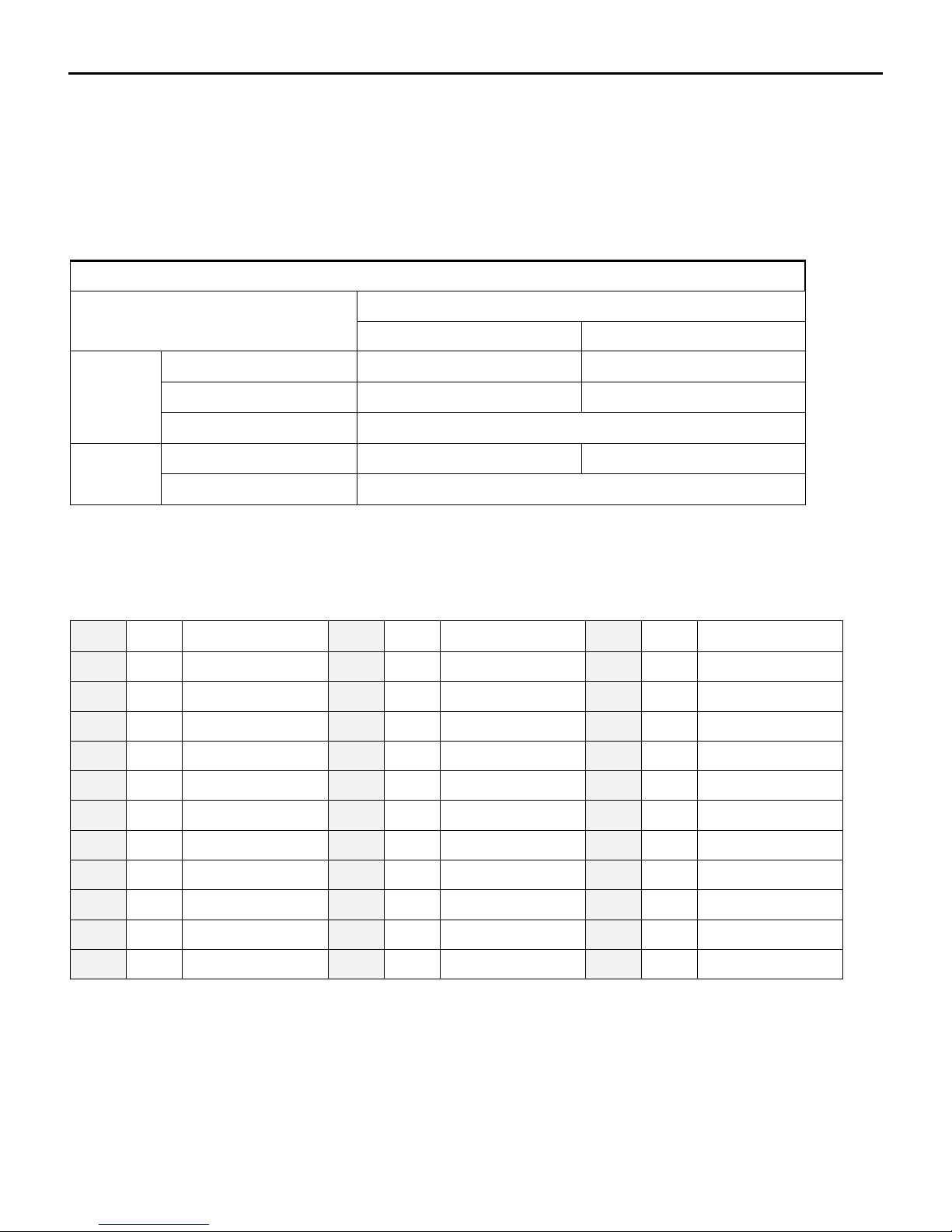
SENSOR TABLES
Note sensor values on the table below. If the sensor is disconnected, placed at a fixed temperature and
the resistance measured, it should be close to the values below.
Table 5
Sensor Resistance Chart for TE6000EA3
Table 6
Reference resistance is 1035 ohms at 77°F. Resistance tolerances are ±0.05 to 0.15% at 77°F. Temperature
range +32 to +104°F.
18 of 21 Jan 13 R5
Page 19

A C-TRAC3
SERVICE NOTES
Dehumidification Mode
Any temperature reset methods used for normal operation are still active to affect the reheat temperature
if the equipment is enabled to dehumidification mode.
Room Sensor/Setpoint
The standard modulating room sensor is a Johnson Controls® TE-6100-960 that comes complete with a
setpoint dial. Optionally, the setpoint dial in the room can be disabled in favor of the second setpoint dial
on the face of the C-TRAC3.
Field Installed Discharge Air Sensor
The location of this sensor is critical to the performance of the equipment and is the most likely cause of
poor temperature control. If it is too close to the heat exchanger it may pick up radiant heat and cause the
equipment to discharge an actual temperature much lower than what is being read by the
C-TRAC3. If it is mounted too far downstream there will be too much lag in the response of the change in
temperature, and will cause the actual discharge temperature to hunt up and down. Refer to the
equipment Installation Operation and Maintenance manual for mounting location details.
DJM2 Setup Notes
Set the DJM2 heating controller to be a fully proportional control by adjusting the CONT potentiometer to
the full counter clockwise position. Adjust the BMSS pot so that the burner comes on at 3.0Vdc and the
BMSZ pot so that the burner shuts off at 2.5Vdc. The precision of the BMSS and BMSZ pots is not overly
critical as the
C-TRAC3 will learn at what input the burner comes on and off, and will adjust its internal temperature
algorithms to compensate for any error.
G-TRAC2 Setup Notes
Add a 1k ohm resistor between G-TRAC2 terminals Q and U. Set block ‘C’ DIP switch 5 to disable the low
limit, and set 3 and 4 to the closed position. Block ‘A’ DIP switches 1, 2, 3, 4 and 5 must be off. With the
C-TRAC3 calling for maximum heat (10 Vdc into G-TRAC2 terminals + and -), adjust the BMS reset pot so
that the burner reaches full fire at 9.25Vdc (G-TRAC2 terminals PL and PG). The gas valve actuator will be
near fully open.
Two Speed Motors
Generally two speed motors do not present a problem to the stability of C-TRAC3 controller. It may,
however, be configured to operate similar to a VFD, using load shedding and minimum position
compensation. In this case, when the motor is turned to high speed, a contact between terminals V and
MP will close to notify the C-TRAC3 of high speed.
Tandem Compressors
If all the compressors are connected to the C-TRAC3 output contacts, there are no programming changes
required. However if the second compressor of the tandem set is operated from a pressure switch the
C-TRAC3 inter-stage time is increased to 8 minutes minimum.
19 of 21 Jan 13 R5
Page 20
A C-TRAC3
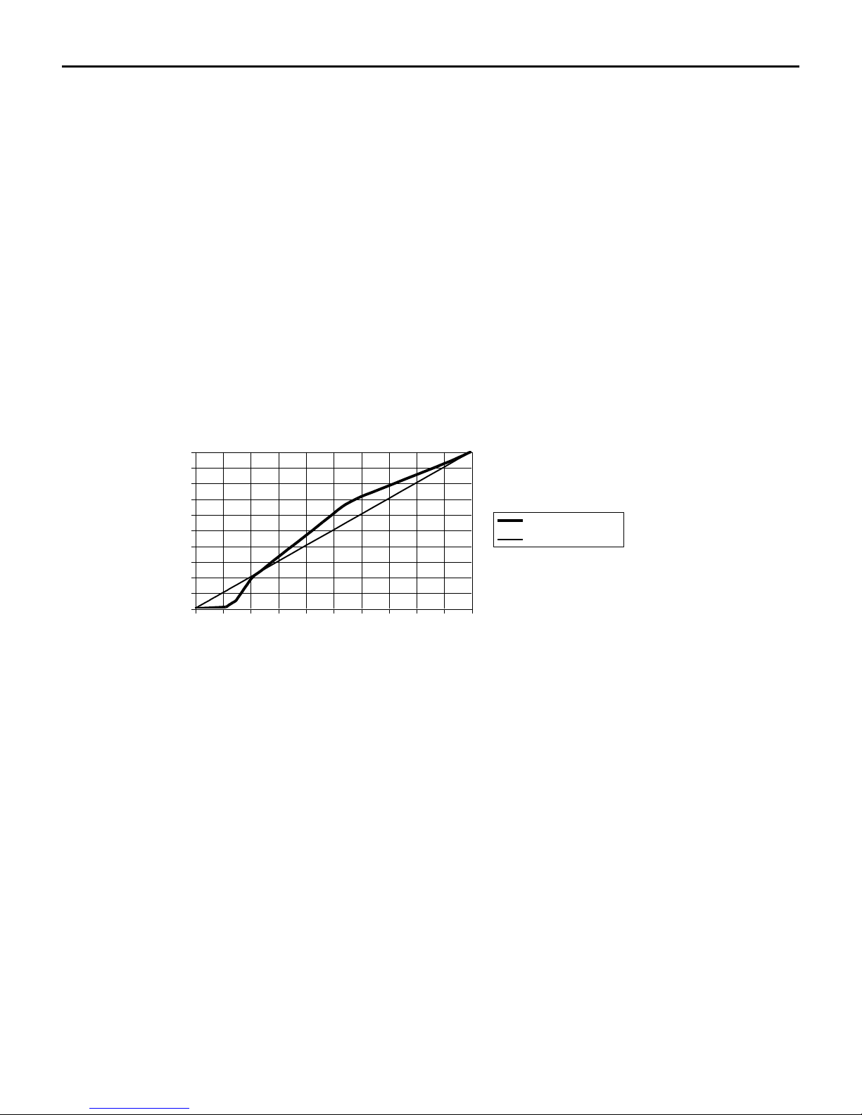
C-TRAC3 Damper Linearization Curve
0
10
20
30
40
50
60
70
80
90
100
0 1 2 3 4 5 6 7 8 9 10
Output to Actuator Vdc
Input %
C-TRAC3 Output
Linear Output
Air Quality Sensors
Generally these sensors output a modulating 0-10Vdc signal based on the levels of impurities in the air.
The signal is connected to the MP terminal on the C-TRAC3 to override the base minimum position.
Normally the minimum position pot located on the face of the C-TRAC3 sets the base minimum. Note that
here are additional connection methods that can achieve the same result. Check with the wiring diagram,
terminal designation sheet and unit function sheet.
Damper Linearization Curve
As a set of dampers open, the amount of static pressure drop decreases. However it does not decrease
proportionally. Because of this the C-TRAC3 uses an output curve to the damper actuator(s) that tries to
match the actual airflow with the required airflow. For example, an input signal of 1.5Vdc (15%) will
output 1.9Vdc to the actuator. The actual air flow will be near 15%.
EMS Control
Energy Management Systems incorporating BACnet or Modbus communication protocols, or a nearby
computer using Engineered Air SMC software, may be connected to the C-TRAC3 for remote monitoring
and control of temperature setpoints, minimum damper positions and enabling operational modes and
control. Review the associated manual supplied with the equipment for additional information.
Face Mounted Setpoints
Some applications do not require the use of one or both of the setpoint knobs mounted on the face of the
C-TRAC3. If not required, the ‘Not Used’ check box will be ticked, with the note ‘Set at Max’ below it.
Setting the knob below maximum may cause the C-TRAC3 to have higher than expected setpoints.
Multizone Setpoint Calculation
Multizone program setpoints are configured somewhat differently from other programs. The SMC
software allows the user to input the minimum and maximum cold deck temperatures, and the maximum
hot deck temperature. The minimum hot deck temperature is based on an adder to the minimum cold
20 of 21 Jan 13 R5
Page 21

A C-TRAC3
deck temperature setpoint. The adder is selected from a drop down list in the program ranging from 10 to
30°F.
21 of 21 Jan 13 R5
 Loading...