

EngA C-TRAC3 Installation, Operation And Maintenance Manual
UNIT MODEL NO. _________________
UNIT SERIAL NO. _________________
SERVICED BY: ___________________
TEL. NO: ________________________
CANADIAN
HEAD OFFICE
AND FACTORY
USA
HEAD OFFICE
AND FACTORY
CANADIAN
EASTERN FACTORY
1401 HASTINGS CRES. SE
CALGARY, ALBERTA
T2G 4C8
Ph: (403) 287-4774
Fx: 888-364-2727
32050 W. 83rd STREET
DESOTO, KANSAS
66018
Ph: (913) 583-3181
Fx: (913) 583-1406
1175 TWINNEY DRIVE
NEWMARKET, ONTARIO
L3Y 5V7
Ph: (905) 898-1114
Fx: (905) 898-7244
SALES OFFICES ACROSS CANADA AND USA
Retain instructions with unit and maintain in a legible condition.
Please give model number and serial number when contacting
Engineered Air for information and/or parts.
A
INSTALLATION, OPERATION
AND MAINTENANCE MANUAL
FOR
C-TRAC3
COOLING CONTROLLER
Jan 13 R5
www.engineeredair.com
A
Warning:
This unit is connected to high voltages. Electrical shock or death could occur if
instructions are not followed. This equipment contains moving parts that may start
unexpectedly. All work should be performed by a qualified technician. Always
disconnect and lock out power before servicing. DO NOT bypass any interlock or
safety switches under any circumstances.
C-TRAC3
If any errors or omissions are noted please contact Engineered Air – Calgary Service at
(403) 287-2590 or Fax (403) 287-4799 or email service@engineeredair.com.
To ensure warranty is honored, only a qualified HVAC service person, who has received training on the
C-TRAC3, should be employed for service and troubleshooting. If further information is required please
contact the nearest Engineered Air office.
Under no conditions (except for temporary copying) should the unit function description be removed from
the unit. There are two copies provided with the unit. One is in an envelope for copying, then return it to
the unit or store in a safe place. The other is attached to the control panel door and should never be
removed. If a copy of the function for a particular unit is needed, contact Engineered Air with the unit
serial number, C-TRAC3 model number (ex model C-TRAC3.3.1) and the C-TRAC3’s program number noted
near the top right corner of the controller. The program number should also be noted on the electrical
drawing.
2 of 21 Jan 13 R5

A C-TRAC3
Table of Contents
INTRODUCTION ................................................................................................................................................................ 5
STARTUP AND SHUT DOWN ............................................................................................................................................. 5
SERVICE SWITCH ............................................................................................................................................................... 5
TEMPERATURE CONTROL ................................................................................................................................................. 6
BASE SETPOINT ................................................................................................................................................................. 6
SETPOINT RESET ............................................................................................................................................................... 6
SETPOINT LIMITS .............................................................................................................................................................. 6
MODES OF OPERATION .................................................................................................................................................... 6
SENSOR #2 ........................................................................................................................................................................ 7
MEASURING TEMPERATURE AND SETPOINT ................................................................................................................... 7
OPERATION ....................................................................................................................................................................... 7
AMBIENT SENSING ............................................................................................................................................................ 8
BLOWER CONTROL ........................................................................................................................................................... 8
ECONOMIZER MODE ........................................................................................................................................................ 8
MINIMUM POSITION ........................................................................................................................................................ 9
Ambient Compensation .................................................................................................................................................. 10
HEATING MODE .............................................................................................................................................................. 10
COOLING MODE .............................................................................................................................................................. 10
DUAL MODE .................................................................................................................................................................... 10
OCCUPIED/UNOCCUPIED ................................................................................................................................................ 11
INDICATION AND DIAGNOSTIC LIGHTS ........................................................................................................................... 11
LOW LIMIT ...................................................................................................................................................................... 13
VARIABLE AIR VOLUME .................................................................................................................................................. 13
WIRING ........................................................................................................................................................................... 14
EMS Wiring ..................................................................................................................................................................... 15
TROUBLE SHOOTING ...................................................................................................................................................... 15
BASIC (MULTIMETER) ..................................................................................................................................................... 15
DIP Switches (C-TRAC 3.2 and higher) ............................................................................................................................ 15
SIMULATING A HEAT/COOL CALL ................................................................................................................................... 16
ENCHANCED (COMPUTER) ............................................................................................................................................. 16
Calibration ...................................................................................................................................................................... 17
SENSOR TABLES .............................................................................................................................................................. 18
SERVICE NOTES ............................................................................................................................................................... 19
3 of 21 Jan 13 R5
A C-TRAC3
4 of 21 Jan 13 R5
A C-TRAC3
The C-TRAC3 is designed to control Engineered Air equipment only. It is not designed to simulate or
copy other controllers on the market today, nor can it be modified to do so.
CAUTION:
All of the remote wiring must be complete and functional before attempting to start
the unit.
CAUTION:
It is important that the service technician understands the C-TRAC3 is a configurable
controller. While the terminal designation remains the same, the operation of the
terminal is dependent on the required function, and may differ from unit to unit.
The C-TRAC3 is not field programmable. If the C-TRAC3 program becomes damaged or corrupted, it
must be replaced or returned to Engineered Air for re-programming.
INTRODUCTION
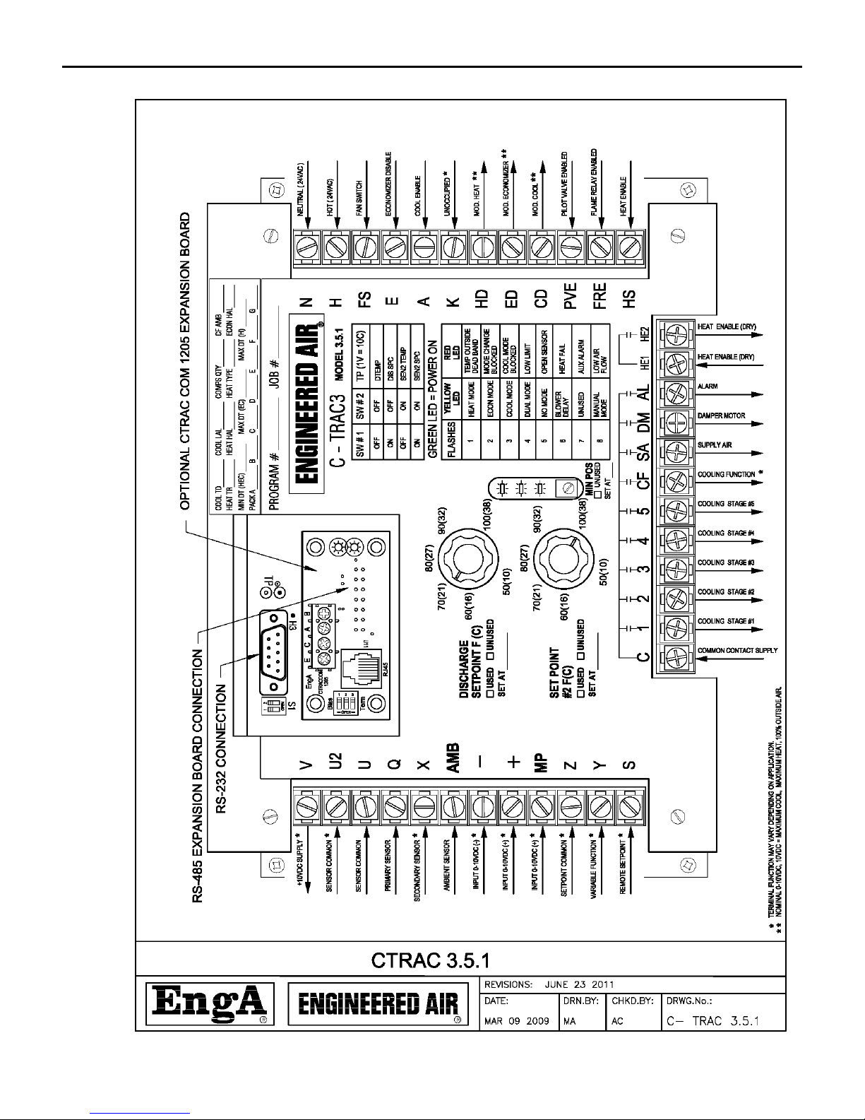
The CTRAC-3 is designed to control the cooling, heating, mixing economizer and fan(s). Additionally, it
allows for independent control of other types of equipment operations such as multi-zone and
dehumidification.
The CTRAC-3 requires a 24Vac grounded power supply. The fuse is located on the back of the control, and
has a rating of 800mA (slow blow). Fuse failure can be checked by having 24Vac across terminals H and N,
but the small green light on the face of the C-TRAC3 is not illuminated. There should also be no Vdc
reading across V and Z.
This information in this manual should be used in conjunction with the unit function sheet(s) and the
terminal designation list that accompanied the equipment.
The C-TRAC3 configuration program number is noted on the face of the C-TRAC3. This number is
important when contacting the factory about the unit operation, or for replacement parts. This number
should accompany the unit serial and tag number, and model number.
STARTUP AND SHUT DOWN
Startup and shutdown should always be accomplished by the use of the remote start contacts and/or
switches, or the unit on/off switch or an EMS control signal. This will allow the C-TRAC3 to disable unit
operation in sequence, protecting the unit components from damage.
SERVICE SWITCH
The service switch, located in the main electrical control panel, is designed for service and maintenance
use only, and should not be used to regularly enable or disable normal operation. Once the unit has
5 of 21 Jan 13 R5

A C-TRAC3
Additional details regarding startup and shutdown are noted in the unit function and in the Installation,
Operation and Maintenance manual.
completely shut down, turn the main disconnect switch off prior to attempting any service or
maintenance.
TEMPERATURE CONTROL
BASE SETPOINT
The C-TRAC3 is designed to be a discharge air temperature controller. The base discharge air temperature
setpoint is typically set from the setpoint 1 control knob located on the face of the
C-TRAC3. Optionally, this setpoint may be replaced by a remote mounted potentiometer, directly set from
a remote BMS signal (0-10Vdc), preset from a computer, or commanded from an EMS signal. If not used,
set this knob to maximum (fully clockwise), as noted on the face of the C-TRAC3.
The C-TRAC3 has the ability to perform 2 independent operations at the same time, such as a
dehumidification system (pre-cool and reheat) or a multizone system (hot deck, and cold deck). These
types of systems normally incorporate both face-mounted setpoint dials, but the optional setpoints noted
above can still apply to both or either setpoint. As above, if setpoint 2 is not used, set to maximum, as
indicated on the face of the C-TRAC3.
SETPOINT RESET
The base discharge air temperature is normally modified from a remote signal to maintain the desired
temperature of the supplied space. This is called reset. The C-TRAC3 discharge temperature can be reset
from a variety of sources such as ambient air temperature, modulating or staged room thermostats, return
air temperature, or a BMS signal (0-10Vdc).
The resulting change in the discharge temperature setpoint from reset is the actual, or calculated,
discharge air temperature setpoint. This is normally referred to as the SPC.
SETPOINT LIMITS
The discharge air setpoint range is set, and limited to, a specified temperature range programmed prior to
shipment. For example, if the minimum discharge temperature is programmed at 60°F, then that is the
minimum possible temperature setting. Even though the setpoint dial may go as low as 50°F, the
calculated, or actual, setpoint can never go below 60°F.
MODES OF OPERATION
The C-TRAC3 has 3 distinct sequential modes of operation: heating, economizer and cooling. Depending
on ambient conditions the C-TRAC3 may start in any of the three modes. Mode change time is five
minutes (six minutes from heat to mechanical cooling if there is no economizer). If the C-TRAC3 is unable
6 of 21 Jan 13 R5
A C-TRAC3
Mode
Terminal
Operation
Heat
HS
Heating is allowed with 24Vac at the terminal.
Economizer
E
Economizer is disabled to minimum with 24Vac.
Cool
A
Cooling is allowed with 24Vac at the terminal.
CAUTION:
All of the remote wiring must be complete and functional before attempting to start
the unit.
to satisfy the SPC in its present mode and the discharge temperature slips outside of the discharge
temperature dead band then it will begin timing for a mode change. Once the timing is completed, it can
change modes. If the timer is active and the discharge temperature slides back into the dead band, the
mode change timer is reset. If the current operating mode becomes disabled the C-TRAC3 will immediately
move into the next mode. A preprogrammed option can disable the unit operation if no modes are
available. The table below indicates which 24Vac input terminal can enable or disable its corresponding
mode.
Table 1
The C-TRAC3 will not always be able to exactly maintain the SPC. Enabling a cooling compressor, for
example, may cause the discharge temperature to fall below the SPC. When the compressor is disabled
the temperature may rise above the setpoint. On average, however, the discharge temperature will
closely match the SPC.
The C-TRAC3 controls to a +/-2°F dead band of the SPC when in heating and economizer mode. The
cooling dead band is based on the dry bulb temperature drop of each stage of mechanical cooling.
SENSOR #2
The C-TRAC3 is has the option of using, and controlling to, two sensors. Some equipment may incorporate
2 discharge air sensors for improved temperature control. Multi-zone equipment use sensor #1 for the
hot deck, and sensor #2 for the cold deck. Dehumidification equipment use sensor #1 for the reheat
(leaving) section, and sensor #2 for the pre-cool section.
MEASURING TEMPERATURE AND SETPOINT
The calculated setpoint (SPC) and the actual temperature can be monitored using a DC voltmeter and the
temperature test points and a DIP switch block mounted on the face of the C-TRAC3 (located near the
RS232 serial connection). Note that the calculated setpoint includes any resets to the setpoint. Refer to
Table 4 on page 14.
OPERATION
As the C-TRAC3 is configurable and will vary in its operation unit to unit, it is imperative that the unit
function, terminal designation sheet and wiring diagram be reviewed to understand how the control is
operating for each particular application.
7 of 21 Jan 13 R5
 Loading...