

Page 1

H.264 Pentaplex DVR
User’s Manual
Version 1.8
DR-116Q shown
DR-104Q
DR-108Q
DR-116Q
4 8 16
120
240
240
No. of channels
Pictures per Second
The SECO-LARM policy is one of continual development. For that reason, SECO-LARM reserves the right to change prices and specifications without notice.
SECO-LARM is not responsible for misprints.
Tel:
Fax:
16842 Millikan Avenue
Irvine, CA 92606
1-949-261-2999
1-800-662-0800
1-949-261-7326
Web: www.seco-larm.com
Email: [email protected]
Page 2

DVR User’s Manual
1
Page 3

DVR User’s Manual
2
Caution and Preventive Tips
Handle with care, do not drop the unit
Mount the unit in an equipment rack or place it on a solid, stable surface
Indoor use only. Do not place the unit in a humid, dusty, oily, or smoky site
Do not place it in an area with poor ventilation or in an area close to fire or other sources of
heat. Doing so may damage the unit as well as cause fire or an electric shock
When cleaning is necessary, shut down the system and unplug the unit from the outlet
before uncovering the top cover. Do not use liquid cleaners or aerosol cleaners. Use only
a damp cloth for cleaning
Always shut down the system prior connecting or disconnecting accessories, with the
exception of USB devices
This symbol intends to alert the user to the presence of important operating and
maintenance (servicing) instructions in the literature accompanying the
appliance.
This symbol intends to alert the user to the presence of unprotected “Dangerous
Voltage” within the product’s enclosure that may be strong enough to cause a
risk of electric shock.
Page 4

DVR User’s Manual
3
Important Information
Before proceeding, please read and observe all instructions and warnings in this manual.
Retain this manual with the original bill of sale for future reference and, if necessary, warranty
service. When unpacking your unit, check for missing or damaged items. If any item is missing,
or if damage is evident, DO NOT INSTALL OR OPERATE THIS PRODUCT. Contact your
dealer for assistance.
Rack Mounting
Consult with the supplier or manufacturer of your equipment rack for the proper hardware and
procedure of mounting this product in a safe fashion. Avoid uneven loading or mechanical
instability when rack-mounting units. Make sure that units are installed to get enough airflow
for safe operation. The maximum temperature for rack-mounted units is 40 °C. Check product
label for power supply requirements to assure that no overloading of supply circuits or over
current protection occurs. Mains grounding must be reliable and uncompromised by any
connections.
Page 5

DVR User’s Manual
4
Table of Content
1. Overview ....................................................................................................................... 7
2. System Setup ................................................................................................................ 8
2.1 Position the DVR ................................................................................................. 8
2.2 Select Video Format ............................................................................................ 8
2.3 Connect Devices to the DVR ............................................................................... 9
2.4 Rear Panel Connections ...................................................................................... 9
3. General System Setup ............................................................................................... 11
3.1 Front Panel Introduction .................................................................................... 11
3.1.1 LED Definition ...................................................................................... 11
3.1.2 Function Keys ....................................................................................... 12
3.2 Entering OSD Setup Menu ................................................................................ 16
3.2.1 User Management ................................ ................................ ................ 17
3.3 Power Up / Shutdown the DVR .......................................................................... 18
3.4 System Date / Time Setting ............................................................................... 19
3.4.1 Set Date / Time ..................................................................................... 19
3.4.2 Daylight Saving Time ............................................................................ 20
3.4.3 Network Time Protocol Setup ............................................................... 21
3.5 Record Schedule / Quality Setting ..................................................................... 22
3.5.1 Record Mode Setup ............................................................................. 22
3.5.2 Schedule Setup .................................................................................... 23
3.5.3 Preset Record Configuration ................................................................ 23
3.5.4 Per Camera Configuration .................................................................... 24
3.5.5 Record Event Video Only ..................................................................... 24
3.5.6 ezRecord Setup .................................................................................... 25
3.5.7 Data Lifetime ........................................................................................ 26
3.5.8 Circular Recording ................................................................................ 26
3.5.9 Audio Recording ................................................................................... 26
3.5.10 Purge Data ........................................................................................... 27
3.6 Event Setting ..................................................................................................... 28
3.6.1 Internal Buzzer ..................................................................................... 28
3.6.2 Event Icon ............................................................................................ 28
3.6.3 Email Notice ......................................................................................... 28
3.6.4 Email Attachment ................................................................................. 29
3.6.5 Alert Notification Setup ......................................................................... 29
3.6.5.1 Alert Configuration Set .......................................................... 29
3.6.5.2 Alert Notification .................................................................... 29
3.6.5.3 Alert IP .................................................................................. 30
3.6.5.4 Alert Port ............................................................................... 30
Page 6

DVR User’s Manual
5
3.6.5.5 Alert Interval .......................................................................... 30
3.6.6 Event Full Screen ................................................................................. 30
3.6.7 Event Duration ...................................................................................... 30
3.6.8 Per Channel Config .............................................................................. 30
3.6.8.1 Channel Select ...................................................................... 31
3.6.8.2 Video Loss Detect ................................................................. 31
3.6.8.3 Motion Detect ........................................................................ 31
3.6.8.4 Motion Detect Indicator ......................................................... 31
3.6.8.5 Detection Configuration ......................................................... 31
3.6.8.6 Alarm In ................................................................................. 32
3.6.8.7 Alarm Out .............................................................................. 32
4. Basic Operation .......................................................................................................... 33
4.1 View Live / Playback Video ................................................................................ 33
4.1.1 Viewing Modes ..................................................................................... 33
4.1.2 Digital Zoom ......................................................................................... 34
4.1.3 View Live Cameras .............................................................................. 34
4.1.4 View Recorded Video ........................................................................... 34
4.1.5 Taking Snapshots ................................................................................. 36
4.2 Sequence........................................................................................................... 37
4.2.1 Sequence with Main Monitor ................................................................ 37
4.2.2 Sequence with Call Monitor(8CH & 16CH models only) ....................... 37
4.3 Search Recorded Video ..................................................................................... 38
4.3.1 Search by Time .................................................................................... 38
4.3.2 Calendar Search .................................................................................. 39
4.3.3 Search by Event ................................................................................... 40
4.4 Video Export ...................................................................................................... 41
4.4.1 ezBurn Introduction ................................ ................................ .............. 41
4.4.2 Export Normal Video ............................................................................ 42
4.4.3 Export Event Video ............................................................................... 42
4.5 Dome Control ..................................................................................................... 43
4.5.1 Dome Connection ................................................................................. 43
4.5.2 Dome Protocol Setup ........................................................................... 43
4.5.3 RS485 Setup ........................................................................................ 44
4.5.4 Dome Controlling Keys ......................................................................... 44
4.5.5 Setting Preset Points ............................................................................ 46
4.5.6 Calling Preset Points ............................................................................ 47
4.6 System Log Exportation ..................................................................................... 47
5. Remote Monitoring Software ..................................................................................... 48
5.1 Remote Monitoring System Requirements ........................................................ 48
5.2 Installation of Software ....................................................................................... 49
Page 7

DVR User’s Manual
6
5.2.1 Change Internet Settings ...................................................................... 49
5.2.2 Install the Remote Monitoring Software ................................................ 51
5.2.2.1 Login / Logout ......................................................................... 52
5.2.2.2 Software Upgrades ................................................................. 53
5.3 Basic Operation ................................................................................................. 53
5.3.1 View Live Video .................................................................................... 53
5.3.1.1 Select Display Mode ............................................................... 54
5.3.1.2 Operating Cameras with Dome Control .................................. 54
5.3.2 Instant Recording ................................................................................. 55
5.3.2.1 Record Video Instantly ............................................................ 55
5.3.2.2 Playback Instant Recorded Video ........................................... 55
5.3.3 Playback Video ................................................................ ..................... 56
5.3.3.1 Playback Remote Video .......................................................... 56
5.3.3.2 Playback Local *.drv Files ....................................................... 57
5.3.3.3 Playback Controls ................................................................... 57
5.3.4 Verify Digital Signature ......................................................................... 59
5.3.5 Search from Event List ......................................................................... 59
5.3.6 Take a Snapshot ................................................................................... 59
5.3.7 Health Status ........................................................................................ 60
5.3.8 Normal and Dual Streaming ................................................................. 60
5.3.9 Remote Monitoring Software Trouble Shooting Guide ......................... 61
6. iPhone and Smart Phone Monitoring ........................................................................ 62
Appendix A: Recommended HDDs ................................................................................ 64
Appendix B: Remote Controller ..................................................................................... 65
Appendix C: Setting up a DVR behind a Router............................................................ 67
Page 8

DVR User’s Manual
7
1. Overview
Lite H.264 DVR is an integrated digital video recorder that combines the
features of a time-lapse audio / video recorder, a multiplexer, and a video
server to create a single security solution.
Its outstanding triplex operation enables users to view live video, search and
playback any recorded video by date/time or event, and remotely monitor the
unit via internet on PC, MEANWHILE the recording of the DVR unit is
ongoing simultaneously.
Lite H.264 DVR is enhanced to provide H.264 compression mode. Moreover,
a marvelous implementation is the brand-new experience of Graphical User
Interface (GUI) that optimizes the monitoring controls of the unit.
Lite H.264 DVR is pre-installed with remote viewing and configuration
software, which is a Web-browser plug-in allowing users to view live or
recorded video images, and enables remote configuration. The remote
software is stored in Lite H.264 DVR and deployed over a LAN, WAN or
Internet connection to remote Windows-based computers. This simplifies the
installation and maintenance of the software components so all remote users
are using the same software coming from the unit.
Page 9

DVR User’s Manual
8
2. System Setup
The notices and introduction on system installation will be described
particularly in this chapter. Please follow the description to operate the unit.
In order to prevent the unit from data loss and system damage that caused by
a sudden power fluctuation, use of an Uninterruptible Power Supply (UPS) is
highly recommended
2.1 Position the DVR
First, note to position / mount the DVR in a proper place and be sure to power
off the unit before making any connections. The placed location should avoid
hindering or blocking the unit from airflow. Enough airflow is needed to
protect the unit from overheating. The maximum allowable temperature of
operating environment is 40°C.
The unit utilizes heat-conducting techniques to transfer internal heat to the
case, especially to the bottom side of the unit.
NOTE: Be sure the rubber feet are not removed, and always leave a
space for air ventilation on the unit’s bottom side.
2.2 Select Video Format
The DVR is designed to operate under either NTSC or PAL video formats.
The switch is on the rear panel.
Page 10

DVR User’s Manual
9
2.3 Connect Devices to the DVR
This section lists some important notices that should be read before making
any connection to the DVR.
Connecting Required Devices
Before power up the unit, cameras and a monitor should be connected to the
unit for basic operation. If needed, connect a call monitor for displaying full
screen video of all installed cameras in sequence.
Connecting Short-term Device
If any short-term devices shall be installed to the DVR as parts of the unit
system, such as USB ThumbDrive® or any USB devices, etc, make sure
those devices are connected only after the unit is powered up. The reason is
because the DVR can recognize the external devices only after the power-up
process is done completely.
2.4 Rear Panel Connections
There are various connectors on the rear panel for the DVR installations. The
following shows the detailed description of each connector.
Main Monitor (BNC/ VGA)
BNC and VGA output connectors are offered for
connecting to a main monitor. The main monitor displays
live image and playback recorded video in either
full-screen or split-window format. VGA output connector
is optional.
Call Monitor (8CH and 16CH models only)
The call monitor is used to display full screen video of all
installed cameras in sequence. The BNC call monitor
connector allows users to connect the DVR with an
optional call monitor.
Video In
A group of BNC connectors is offered for video input
streams from installed cameras. The number of
connectors is equal to the number of channels.
Page 11

DVR User’s Manual
10
Alarm I/O & RS485
A D-Sub connector is provided to offer users the
flexibility to connect the DVR to Alarm I/O and
RS-485 devices. Refer to Setup Guide for
detailed pin definitions.
LAN Connector (RJ-45)
The DVR is capable of networking. Once the unit is
connected to the LAN network, users can remotely
access the unit through the remote software on a PC.
USB Connector (x1)
There is one USB port provided to allow users to connect
a PS/2 mouse via a USB converter.
Power Jack
The DVR has a free voltage DC power connection jack.
Please connect the power adapter shipped with the unit.
Audio In
Audio In connectors are offered for connecting
audio source devices to the unit. 4CH models
offer RCA connectors while 8CH and 16CH
models offer a D-Sub connector.
4CH models
8CH & 16CH models
Audio Out – Main & Call
Main & Call Audio Out RCA connectors are
provided for connecting the DVR to audio output
devices (e.g. amplified speakers). “Main” will
output audio from the main monitor, whereas
“Call” will output audio form the call monitor.
NOTE: Call Audio Out RCA connector is only available for 8CH and
16CH models.
Page 12

DVR User’s Manual
11
3. General System Setup
Before operating the DVR, some general configuration should be setup first.
The following subsections will introduce function keys on the front panel and
general configuration of the DVR.
The regular displayed OSD information and its displayed positions are shown
as following figure. Title of the channel will be displayed on the top-left corner
of the window, either in full screen mode or in multiple channel mode. The
current operating mode, including Call mode, Dome Control mode, Playback
mode, Freeze mode and Sequence mode, will be displayed on the
bottom-left corner of the screen. The date/ time information will be display on
the bottom-right corner of the screen. On the upper-right corner will show the
authority level of login account. Under logout condition, the icon will show “N”.
Ch1
►*1
N
2008/05/09 PM04:31:22
3.1 Front Panel Introduction
The front panel controls enable users to control the unit and preset the
programmable functions.
3.1.1 LED Definition
The LEDs on the front panel of the DVR are described as follow.
Power LED
The LED lights up when the correct power is connected to the unit.
REC LED
The LED blinks while the DVR is recording.
Alarm LED
The LED lights up when an alarm is triggered.
Network LED
The LED lights up when the DVR is connected to a network and
blinks when the data is being transferred.
Page 13

DVR User’s Manual
12
3.1.2 Function Keys
This section describes the functional keys on the front panel of the DVR.
Refer to the Setup Guide for the graphical illustration of functional keys.
CHANNEL
In both Live and Playback modes, press the CHANNEL key to view the
corresponding video in full screen. The number of the CHANNEL keys
corresponds to the number of cameras supported by the unit.
In Dome Control mode, the key “1” is used to access the Set/Go preset
menu; the key “2” is used to hide or display the hint screen.
In OSD virtual keyboard, press keys 1~9 to input number 1~9, and press
key 10 to input number 0.
DOME
Press the key to enter dome control mode. Please refer to Section Dome
Control for detailed controlling operation.
In OSD virtual keyboard, press this key to go backspace.
MODE
Press repeatedly to select for wanted monitor display format. The available
view modes includes: full-screen, 4-window (2× 2), 9-window (3× 3) and
16-window (4×4). Refer to Section Viewing Modes for detailed information.
SEQ (Sequence)
Press to start automatic sequence display of video from all installed cameras.
MENU
Press this key to enter the OSD setup menu.
COPY
In Playback mode, press COPY to select the start and end time of the export
video. Refer to Section Video Export for detailed information.
CALL (8CH and 16CH models only)
In Live mode, press this button to enter call monitor control mode.
In Dome Control mode, press CALL in association with ENTER to enter
the OSD setup menu of the dome camera.
Page 14

DVR User’s Manual
13
In OSD virtual keyboard, press this key to input a period mark “.”.
Page 15

DVR User’s Manual
14
PLAY/STOP
Press this key to switch between live image and playback video.
NOTE: According to record setting, part of the latest video cannot be
played back because the video is still saved in the buffer.
FREEZE
Press FREEZE while viewing live image, the live video will be frozen. The
date / time information shown on the monitor will continue updating. Press
FREEZE again to return to live mode.
Press FREEZE while playing the recorded video, the playback video will
be paused. Press LEFT / RIGHT to move the recorded video reverse /
forward by single step. Press FREEZE again to continue playing video.
SEARCH
In both Playback and Live mode, press SEARCH to enter the Search
menu to search and playback recorded video by date/time or events.
Press twice to instantly playback the latest recorded videos.
ESC
Press to cancel or exit from certain mode or OSD setup menu without
changing the settings made previously.
If password protection is enabled, press ESC for five seconds to lock up
functions of certain keys, including PLAY, MENU, SEARCH, DOME and
CALL. Once users lock up the functions of these keys, enter proper
username and password to unlock.
NOTE: Please go to the <System Setup> <User Management>
menu to enable or disable the password protection.
Direction Keys
In Zoom mode, press these keys to move to desired directions.
In the OSD setup menu, the LEFT/ RIGHT keys are used to move the
cursor to previous or next fields. To change the value in the selected field,
press UP/ DOWN keys.
ENTER / ZOOM
In OSD setup menu or selection interface, press this key to make the
selection or save settings.
In live full screen view mode, press this key to view a 2× zoom image;
Page 16

DVR User’s Manual
15
press it again to exit Zoom mode.
Page 17

DVR User’s Manual
16
3.2 Entering OSD Setup Menu
The configuration of the DVR can be customized by entering the intuitive
Graphical User Interface (GUI) OSD setup menu. Collaborating with a USB
mouse, setting up the DVR can be easy as operating on a PC. Press MENU
and input a valid username. There are two preset accounts: “admin” and
“user”. “admin” can be inputted via pressing the hot key MENU, while “user”
can be inputted via pressing the hot key SEARCH. Move to <OK> and press
ENTER to proceed.
Input Username
A B C D E F G H I J K L M N O P Q R S T U V W X Y
Z
a b c d e f g h i j k l m
n o p q r s t u v w x y z 0 1 2 3 4 5 6 7 8 9 . !
@
# − _ , “ + = *
◄ ►
Backspace Delete
Cancel
OK
The next step is to enter a corresponding password. The preset password for
“admin” is “1234”, and the password “4321” is for “user”.
Password Verification
_______
Press Channel Keys To Enter Password
(4-8 Digits)
Press ◄ Key To Delete
NOTE: It is strongly suggested to change the preset password to
prevent unauthorized access to the unit.
An icon displayed at the upper-right corner of the screen will show the
authority level of the account. Under logout condition, the icon will show “N”.
When an account is logged in, its authority level number (1~8) will be shown.
Before completely logout, other functions can also be accessed without
having to login again. There are two ways to logout: manually logout by
pressing ESC key at Live mode, or auto logout when keys are not pressed for
5 minutes at Live/ Menu mode.
Page 18

DVR User’s Manual
17
3.2.1 User Management
The DVR provides the option to create up to seven sets of usernames and
passwords with customized authority, excluding the preset “admin” account.
From the Main Menu, select <System Setup> <User Management> and
the menu is as the following:
User Management
Password Protection
Account Setup
Authority Setup
Load Default Setting
ON
No
Password Protection
Select <ON> to request for username and password for accessing functions
listed in Authority Setup menu, or select <OFF> to allow free access.
Account Setup
Setup customized username, password, and authority level in this menu. The
username is case sensitive. The authority level is ranked from level 1~8, and
level 8 has highest authority. Alternatively, select <Disable> to suspend the
account.
NOTE: The username and authority level of the preset “admin”
account cannot be changed.
Authority Setup
Setup the allowed authority level for accessing the functions listed in this
menu. The functions include: Playback/Search, Dome Control, Call Control,
Export Data, Menu Access, System Setup, Monitor Setup, Camera Setup,
Record Setup, Sequence Setup, Event Setup, Database Setup,
Configuration and Shutdown. The authority level is ranked from level 1~8,
and level 8 has highest authority. Alternatively, select <Disable> to allow free
access.
NOTE: The “Menu Access” cannot be set to <Disable>. When the
account does not have authority to access certain functions, an error
message will be displayed on the screen.
Load Default Setting
Select <Yes> to load the default setting.
Page 19

DVR User’s Manual
18
3.3 Power Up / Shutdown the DVR
If the DVR must be shutdown for any reason, please use the proper shut
down and power up procedures to avoid damaging the DVR.
Power Up the Unit
Simply plug in the power adapter that came with the package and the DVR
will start to boot.
The color bar and system checking information will be shown on the monitor
and then disappear when the unit has been completely powered up.
Restart / Shutdown the Unit
Press MENU and input the username and password that has sufficient
authority to access the OSD setup menu. Select <Shutdown> in Main Menu
and press ENTER to enter the Shutdown menu, which displays as follows.
Shutdown
Power Off
Reboot
Execute
Execute
<Power Off>
Select this item to shut down the unit. Do not remove the power during shut
down until the message “You can safely turn off DVR now!” displays.
<Reboot>
Select this item to reboot the unit. The color bar and system checking
information are displayed on the monitor until the unit is completely restarted.
Page 20

DVR User’s Manual
19
3.4 System Date / Time Setting
Users can set the current date, time and other OSD parameters in Date/Time
menu (under System Setup menu). The login account should have authority
to access the System Setup menu. In OSD setup menu, select <System
Setup> and press ENTER, then select <Date/Time> to access the Date/Time
menu; the menu displays as follows.
Date/Time
Date
Time
Time Zone
Date/Time Display
Date Display Mode
Time Display Mode
Date/Time Order
Daylight Saving Time Setup
Network Time Protocol Setup
2008/02/21
PM10:39:26
OFF
1 Row
Y/M/D
12 HR
Date First
3.4.1 Set Date / Time
Set Date / Time
Select <Date> / <Time> and press ENTER to adjust the settings. LEFT /
RIGHT keys are used to move the cursor to previous or next field, ENTER is
for selecting, and UP / DOWN are used to change the value in the selected
field.
NOTE: The new date / time setting applies to record new video. The
date and time of previously recorded video will not be changed.
NOTE: If time settings have to be changed in any case, it is strongly
recommended to format the HDDs to avoid database corruption.
Date / Time Display
Users are allowed to set the time OSD displays in 1 or 2 rows. Use the UP /
DOWN keys to change the setting.
Page 21

DVR User’s Manual
20
Date Display Mode
This function allows users to set the OSD display type of the date. There are
three options to select from: <Y/M/D>, <M/D/Y> or <D/M/Y>. “Y” represents
“Year”, “M” represents “Month” and “D” represents “Day”.
Move to the item and press ENTER, the option starts blinking. Use UP /
DOWN keys to change the setting.
Time Display Mode
Users can set the time format to <12 hour> or <24 hour>. Use the UP /
DOWN keys to change the format.
Date / Time Order
The item is used to set the order of date / time display to <Date First> or
<Time First>. Use UP / DOWN keys to change the setting.
3.4.2 Daylight Saving Time
Daylight Saving Time
The item is for those people who live in certain regions to observe Daylight
Saving Time. Select <ON> to enable, or <OFF> to disable the function.
If the function is disabled, the DST Start / End time and DST Bias will be
grayed out and cannot be accessed.
NOTE: If this function is enabled, the date/ time information will be
shown on the screen with a DST icon when playing back recorded
video or searching video in the event list. “S” indicates summer time
and “W” indicates wintertime.
DST Start / End
The items are used to program the daylight saving duration. Use LEFT /
RIGHT keys to move the cursor to the next or previous field, UP / DOWN to
change the settings in the selected field.
DST Bias
The item allows users to set the amount of time to move forward from the
standard time for daylight saving time. The available options are in minutes.
Page 22
DVR User’s Manual
21
3.4.3 Network Time Protocol Setup
Time Zone
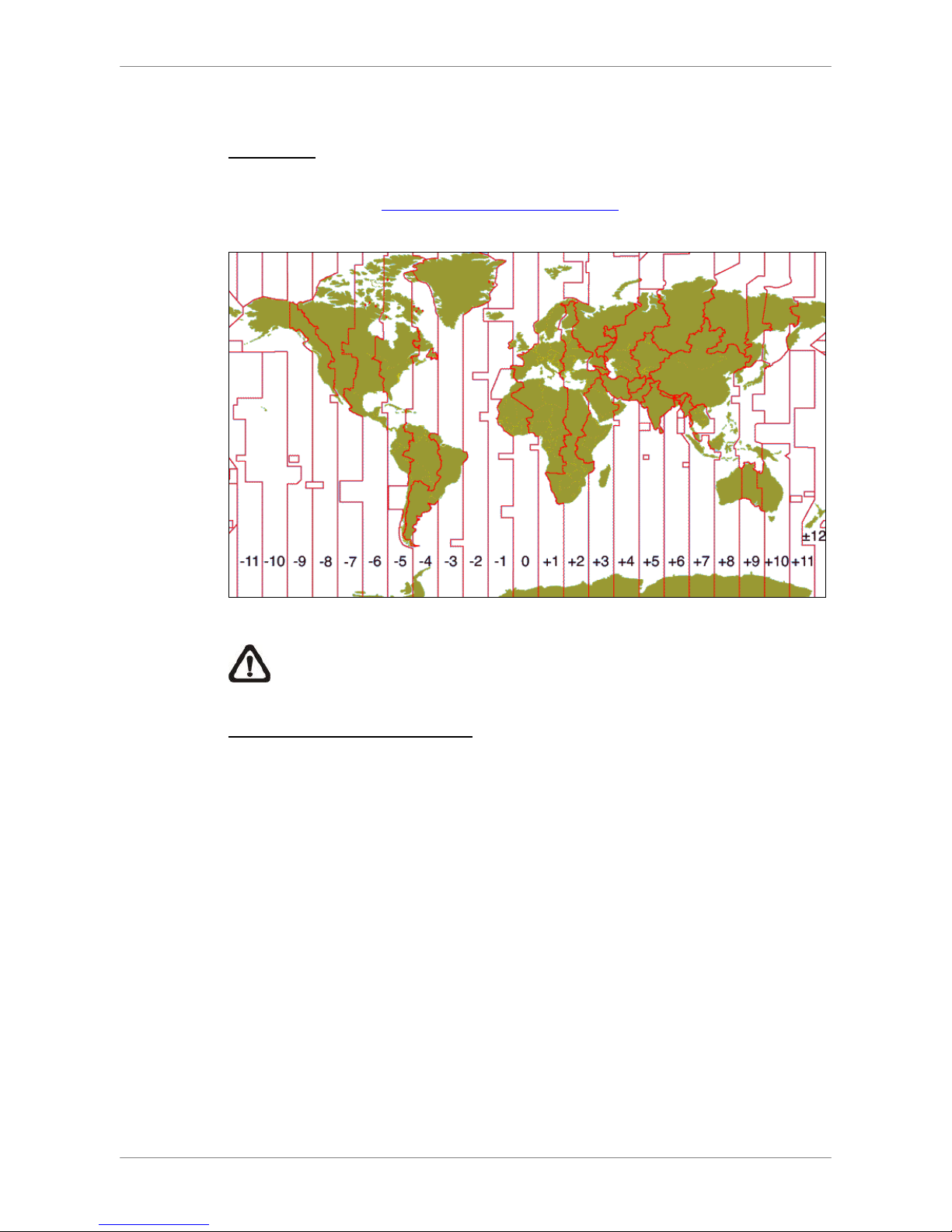
Select <Time Zone> to enter the time zone. To find out the correct local time
zone, please visit www.greenwichmeantime.com or refer to the following
figure.
NOTE: The <Time Zone> must be set to the correct local time zone or
the <Network Time Protocol Setup> will not be accessible.
Network Time Protocol Setup
After entering the time zone, the <Network Time Protocol Setup> option will
appear. Select the <Network Time Protocol Setup> to set the time server.
The default time server is time.nist.gov, but the user can change it to other
time servers when desired. A list of IP addresses of the time servers is listed
below.
129.6.15.28
129.6.15.29
132.163.4.101
132.163.4.102
132.163.4.103
128.138.140.44
192.43.244.18
131.107.1.10
69.25.96.13
206.246.118.250
208.184.49.9
64.125.78.85
207.200.81.113
64.236.96.53
68.216.79.113
After the time server is set, set <Manually Time Sync> to <Yes> to sync the
time. The time sync can also be updated periodically. Set <Automatically
Time Sync> to <ON>, and the time will be automatically synced once an
hour.
Page 23
DVR User’s Manual
22
3.5 Record Schedule / Quality Setting
The Record Setup menu allows users to set recording quality, recording
schedules, and other recording parameters. Login with a proper account to
access Record Setup menu. In the Main menu, move the cursor to <Record
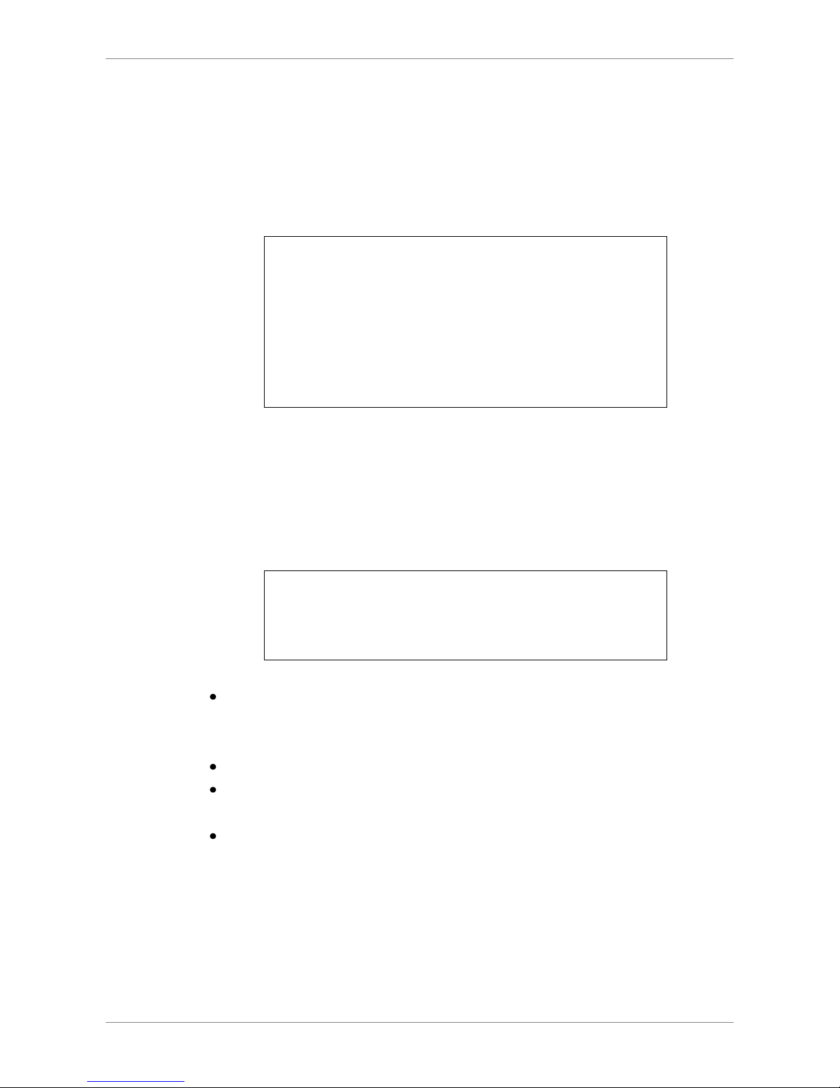
Setup> and press ENTER; the following menu is displayed.
Record Setup
Record Mode Setup
Schedule Setup
Preset Config
Per Camera Config
ezRecord Setup
Data Lifetime
Circular Recording
Audio Recording
Purge Data
Best Quality
0 Days
ON
ON
3.5.1 Record Mode Setup
The Record Mode Setup menu allows users to setup record resolution, etc.
The relative record settings, such as preset configuration, will follow the
record mode setting. The menu is displayed as the following.
Record Mode Setup
Record Resolution
Record Format
Max Rec. PPS
CBR/VBR
720*240
H264
60
CBR
Select record resolution of the video from 720*480, 720*240, and 352*240
for NTSC systems. If the video system is PAL, the options will be 720*576,
720*288, and 352*288.
Select record format of the video from H.264 or MJPEG.
The Max Rec. PPS will be changed automatically according to the record
resolution selected.
Set the recording bit rate as CBR (Constant Bit Rate) or VBR (Variable Bit
Rate).
It is strongly suggested to use VBR encoding when reliable video quality is
the top priority.
Page 24
DVR User’s Manual
23
NOTE: Since a VBR file does not have a fixed size, the HDD space
usage cannot be calculated and thus ezRecord function is not
supported for VBR mode. Therefore, if ezRecord is selected as the
preset record configuration, the option of this menu item will
automatically be set as <CBR>.
3.5.2 Schedule Setup
The Schedule Setup is used to set the day and night time, or weekend
recording schedule. Select <Schedule Setup> from the Record Setup menu
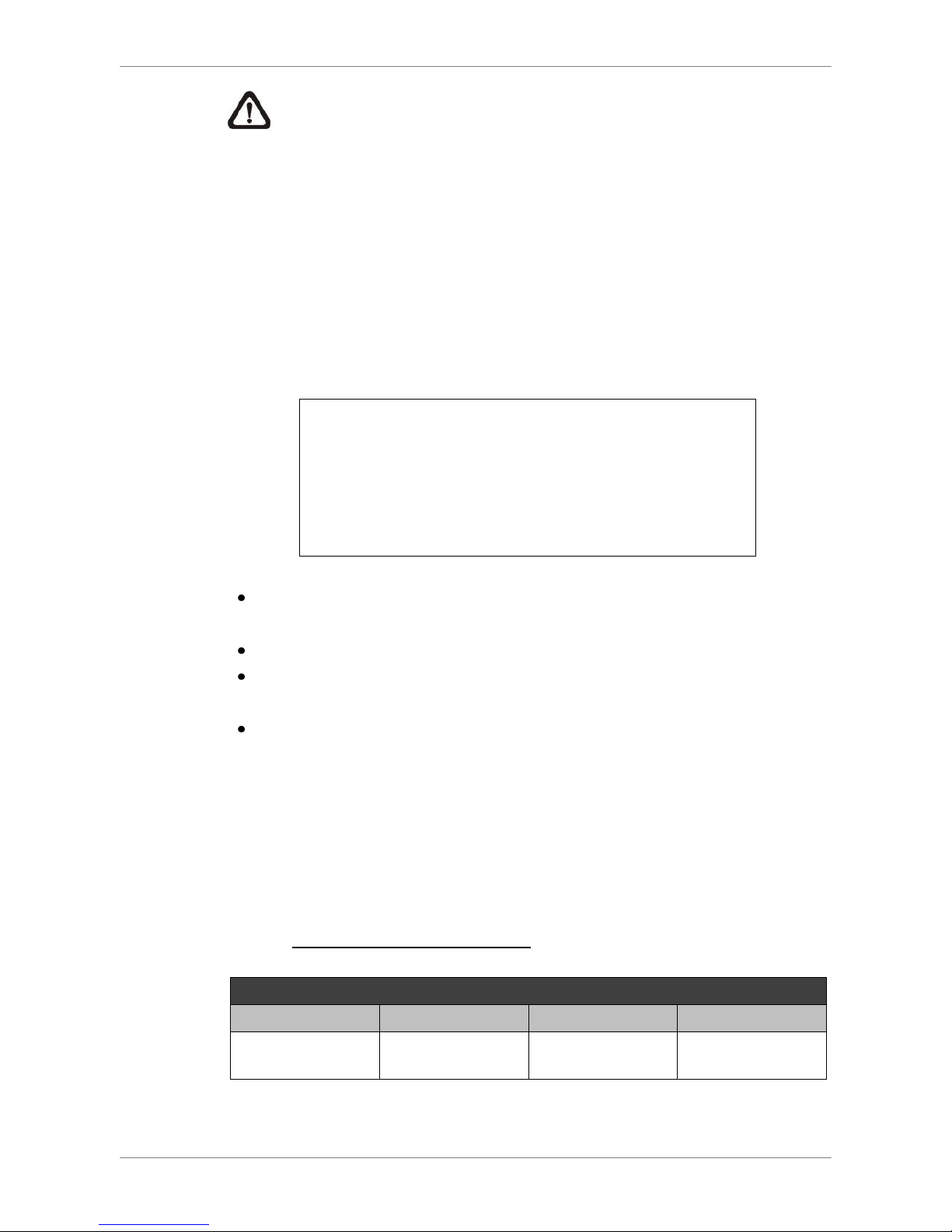
and press ENTER; the following menu is displayed.
Schedule Setup
Day Time Start
Day Time End
Night Time Start
Night Time End
Weekend Schedule
Weekend Start
Weekend End
AM 06:00
PM 06:00
PM 06:00
AM 06:00
ON
Fri 18:00
Mon 06:00
Make appropriate changes of the start time of Day and Night Time using
Direction keys.
Press ENTER to confirm the settings or ESC to cancel.
If a weekend record is required, select <ON> to enable the Weekend
Schedule in advance and then set the Weekend Start/End time.
Press ESC to return to previous page.
3.5.3 Preset Record Configuration
The <Preset Config> is used to select the preset recording quality and frame
rate. In normal circumstances, it is strongly recommended to set the preset
configuration as <Best Quality>. Below table shows the PPS and picture size
under <Best Quality> in Half-D1 mode. Please refer to OSD Setup Manual,
Section Preset Record Configuration for more detailed information.
Halfl-D1 mode (NTSC: 720x240@120PPS; PAL: 720x288@100PPS)
Normal PPS
Normal Size
Event PPS
Event Size
7.5 NTSC
(6.25 PAL)
10 KB / PIC
30 NTSC
(25 PAL)
10 KB / PIC
Page 25

DVR User’s Manual
24
3.5.4 Per Camera Configuration
This function is used to set the Day / Night / Weekend PPS (Picture per
Second) and Quality for each channel. The Preset Configuration must be set
to <OFF> for accessing these schedules. The menu is displayed as below
(Record Mode: 720×240@120PPS in NTSC / 720×288@100PPS in PAL).
Per Camera Config
Cameral Select
Normal PPS
Normal Size
Event Max PPS
Event Size
Event Active
Day
7.5
Mid
30
Best
Both
Night
7.5
Mid
30
Best
Both
CH1
Weekend
7.5
Mid
30
Best
Both
Firstly, select a Camera for setting its record configuration. The image and
recording settings from the selected camera will be displayed on the
screen.
Move the cursor using Direction keys and press ENTER to select an item.
Change the value using UP / DOWN keys.
Press ENTER to confirm the settings or ESC to abort.
Press ESC to return to Record Setup menu.
Please note that the total normal PPS for all channels cannot exceed 120
NTSC (720×240@120PPS) / 100 PAL (720×288@100PPS). To increase one
channel’s PPS, you may have to reduce others’ first. Event PPS is not
restricted to this rule, since a smart event scheduler will handle the total PPS
with a correct weighting.
3.5.5 Record Event Video Only
If the DVR shall start recording only when alarms are triggered, follow the
steps below:
Enter the OSD setup menu with correct password.
In the OSD setup menu, select <Record Setup> menu. Move the cursor to
the item <Preset Config>, and select <Event only>.
Refer to OSD Setup Manual, Section Preset Record Configuration for more
detailed information.
Page 26
DVR User’s Manual
25
3.5.6 ezRecord Setup
This item aims to ease the complicated record settings, and to make the
setup much easier. Note that the item can be reached only when <ezRecord>
is selected as the option for <Preset Config>.
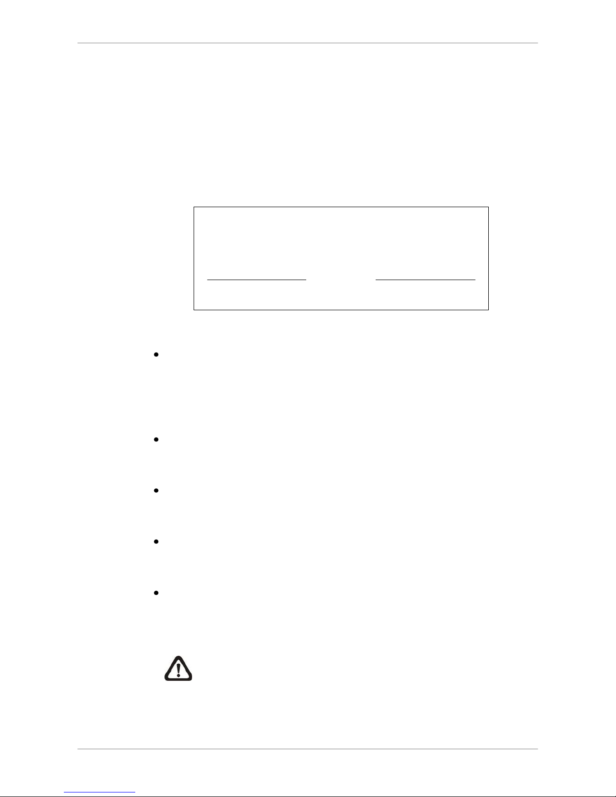
Select <ezRecord Setup> from <Record Setup> and press ENTER, the
sub-menu appears as below figure:
ezRecord Setup
How Many Days To Record
Daytime Record
Night Record
Weekend Record
Average Normal PPS
Average Normal Quality
2 Days
Yes
Yes
Yes
7.5
Best
Follow these steps to Setup ezRecord:
Select <How Many Days To Record> and press ENTER, then press
UP/DOWN to choose an option. The average normal PPS & Quality will
be adjusted automatically. The maximum of days depends of the size of
the installed HDD. In other words, the larger the size of the HDD installed,
the more days the unit can record.
Move to <Daytime Record> and press ENTER. This item will determine
whether the DVR will record during daytime. If yes, use UP/DOWN to
select <Yes> as to enable daytime recording; or select <No> to disable.
Repeat the same procedures through the 3rd and 4th item, respectively.
Note that <Weekend Record> will be inaccessible if <Weekend
Schedule> in <Schedule Setup> is set to <No>.
Select <Average Normal PPS> and press ENTER, then press UP/DOWN
to make a choice. The <How Many Days To Record> will be computed
automatically.
Select <Average Normal Quality> and press ENTER, then press
UP/DOWN to make a choice. The <How Many Days To Record> will be
computed automatically.
NOTE: The current number of connected cameras will affect the
recording quality automatically calculated through the <ezRecord
Setup>. Therefore, once the number of connected cameras is
changed, the <ezRecord Setup> should be reset.
Record Info
Page 27
DVR User’s Manual
26
3.5.7 Data Lifetime
Data Lifetime indicates the duration that a video is saved and recallable in the
HDD. Only those video recorded within Data Lifetime can be displayed on the
screen and played back. The video exceeded Data Lifetime will be hidden
and cannot be retrieved for playback.
Press ENTER to select this item in Record Setup menu, and then use UP /
DOWN keys to set the data lifetime. The value ranges from <1> to <365>
days, or select <0> to disable the function.
NOTE: To play back a video exceeding the data lifetime, please
extend the duration until the recording data / time of the video is
included.
3.5.8 Circular Recording
Users can choose to record video in circular mode or in linear mode. If
circular mode is selected, the DVR will stores new video into the HDD spaces
while overwrite the oldest recorded video. Alternatively, if linear mode is
selected, the DVR will stop recording when the HDD is full. The percentage of
HDD usage will be displayed at the lower-left corner of the screen. Moreover,
a reminder message “ALMOST FULL” will show up at the upper-right corner
of the screen when HDD usage reached 98%. In the mean time, an internal
buzzer will start beeping.
From the Record Setup menu, move the cursor to <Circular Recording> and
press ENTER, then select <ON> / <OFF> using UP / DOWN keys.
3.5.9 Audio Recording
When an audio source device is connected, it will be automatically set to
<ON>, audio input is recorded and saved with the video. When no audio
source device is connected, it will be automatically set to <OFF>.
Page 28
DVR User’s Manual
27
3.5.10 Purge Data
This item is used to delete the Normal or Event recording video. In Record
Setup menu, move the cursor to <Purge Data> and press ENTER; the Purge
Data menu is displayed.
Purge Data
Purge All Data
Purge All Event Data
Purge Event Before
Start To Purge
No
No
2008/01/01
No
Purge All Data
The item is used to delete all recorded video from the database. Set this item
to <Yes using UP / DOWN keys, and start the deletion by setting <Start To
Purge> to <Yes>.
Purge All Event Data
The item is used to delete all event video from database(s). Using UP /
DOWN keys to select <Yes> and start the deletion by setting <Start To
Purge> to <Yes>.
Purge Event Before
The item is used to delete event video before a specific date. Use LEFT /
RIGHT keys to move the cursor to next or previous field, ENTER to select the
item and UP / DOWN to adjust the value.
Start To Purge
After the video or data to be deleted are selected, set this item to <Yes> to
start the deletion or choose <No> to cancel.
Page 29
DVR User’s Manual
28
3.6 Event Setting
This menu allows users to determine the DVR’s behavior in response to
alarm events. In the Main menu, move the cursor to <Event Setup> and
press ENTER. The following menu is displayed. Items in the Event Setup
menu are described in the following subsections.
Event Setup
Internal Buzzer
Event Icon
Email Notice
Email Attachment
Alert Notification Setup
Event Full Screen
Event Duration
Per Channel Config
ON
ON
OFF
OFF
None
20 Sec
3.6.1 Internal Buzzer
This item allows users to enable / disable internal buzzer of the DVR. If <ON>
is selected, the buzzer is activated in response to alarm events. If <OFF> is
selected, the buzzer is not activated.
3.6.2 Event Icon
This item enables (ON) / disables (OFF) the display of event icons on the
monitor when alarm events occur. The event icons are represented by a
character according to the event types respectively. Refer to the following
table for association of event icons and event types.
Event Icon
Event Type
A
Alarm in event
M
Motion detection event
L
Video loss event
3.6.3 Email Notice
The item enables (ON) / disables (OFF) the Email notification of an event.
When an alarm event is triggered and <Email Notice> is enabled, an e-mail
concerning the alarm event will be sent.
NOTE: In order to send an event notification e-mail successfully,
ensure that the DVR is connecting to the internet.
Page 30
DVR User’s Manual
29
3.6.4 Email Attachment
The function allows the DVR to send out a brief AVI video regarding the event.
The number of the attached AVI video will be equivalent to the number of
cameras connected to the DVR. For example, if the DVR has been
connected with 8 cameras, then 8 videos will be attached to the notice email.
The total size of the video will be about 2 MB. Select <ON> to enable this
function; or <OFF> to disable it.
NOTE: The video clips of the Email Attachment will ONLY be in *.avi
format. Please download the Divx Player from www.divx.com to play
the *.avi files.
3.6.5 Alert Notification Setup
This function allows users to send alert notifications to the CMS software
which had been installed to users’ computer. For further setup instruction at
the CMS side, please refer to the CMS user’s manual.
Alert Notification Setup
Alert Configuration Set
Alert Notification
Alert IP
Alert Port
Alive Interval
1
OFF
0.0.0.0
9999
120 Sec
3.6.5.1 Alert Configuration Set
<Alert Configuration Set> provides 3 combinations of Alert Notification, IP,
Port, and Interval.
3.6.5.2 Alert Notification
4 options are included in this item: <OFF>, <Event>, <Alive>, and <Both>.
<OFF>: The Alert Notification is turned off.
<Event>: When the alarm is triggered, the DVR will send an alert message to
the CMS.
<Alive>: The DVR will send an alive message to the CMS every N second
just to show you that the connection between the DVR and CMS is
in effect. The time interval N can be adjusted in <Alive Interval>.
<Both>: This enables the DVR to send both Event and Alive alert messages
to the CMS.
Page 31

DVR User’s Manual
30
3.6.5.3 Alert IP
The Alert IP must match the IP address of the computer installed the CMS.
3.6.5.4 Alert Port
The ports for DVR and the CMS Alert MUST be the same.
3.6.5.5 Alert Interval
Users can define the time interval (1 to 255 seconds) between each alive
message.
3.6.6 Event Full Screen
This function allows the DVR to display the alarm channel in full screen size
when an alarm is triggered. Select <None> to disable this function; select
<Main> to display the alarm channel on Main Monitor when an alarm is
triggered; select <Call> to display the alarm channel on Call Monitor; and
select <Both> to display the alarm channel on both Main Monitor and Call
Monitor.
3.6.7 Event Duration
This item determines the duration of the buzzer and Alarm Out relay function
after an alarm is triggered. The available event duration range is from 5
second to 999 seconds.
3.6.8 Per Channel Config
This menu is used to configure the <Video Loss Detect>, <Motion Detect>,
<Alarm In> and <Alarm Out> settings for each channel. The menu is
displayed as below.
Per Channel Config
Channel Select
Video Loss Detect
Motion Detect
Motion Detect Indicator
Detection Config
Alarm In
Alarm Out
CH1
OFF
OFF
ON
OFF
ON
Page 32

DVR User’s Manual
31
3.6.8.1 Channel Select
The item is used to select a desired channel for setting the parameters. Move
the cursor to <Channel Select> and press ENTER, then select a channel
using UP / DOWN keys. Press ENTER again to confirm the selection.
3.6.8.2 Video Loss Detect
This item allows users to enable or disable Video Loss as an alarm event.
Select <ON> to enable Video Loss alarm events, or <OFF> to disable.
3.6.8.3 Motion Detect
This item allows users to enable or disable motion detection function of the
DVR. Select <ON> to enable Motion Detect alarm events, or <OFF> to
disable. If motion detection function is enabled, it is required to define motion
detection parameters such as detection area and sensitivity settings in
<Detection Config>.
3.6.8.4 Motion Detect Indicator
This item allows users to display/ hide the motion detection indicators. Select
<ON> to display the indicators, or <OFF> to hide them.
3.6.8.5 Detection Configuration
If motion detection function is enabled, it is required to define the motion
detection parameters such as detection area and sensitivity settings. Select a
channel for setting the parameters, move the cursor to <Detection Config>
and press ENTER. The Detection Configuration menu displays as follows.
Detection Config
Detected Area Setup
Sensitivity
Block Threshold
88%
4
Detected Area Setup
After selected this item, the detected area is displayed as follows. The
detection area consists of 192 (16×12) detection grids.
Page 33

DVR User’s Manual
32
Use the Direction keys to move the cursor and press ENTER to select or
de-select a grid. Press MODE to select all of the grids for detection; press
MODE again to de-select all of the grids.
Sensitivity
This item is used to set the sensitivity of detection grids for the camera. A
greater value indicates more sensitive motion detection. A motion alarm will
be triggered once the amount of motion detected exceeds the Threshold
value.
Move the cursor to <Sensitivity> and press ENTER, and then use UP/ DOWN
keys to adjust the value. The value is increased by 4% increment.
Block Threshold
<Block Threshold> indicates the motion alarm triggered level; select from
<1> to <16>. Selecting <1> means the DVR will trigger the alarm when one
grid is detected; and selecting <16> means the DVR will trigger the alarm
when 16 grids are detected. Move the cursor to <Block Threshold> and press
ENTER, and then use UP / DOWN keys to adjust the value.
3.6.8.6 Alarm In
This item allows users to enable/ disable alarm input detection. According to
users’ application, select <N/O> (Normal Open) or <N/C> (Normal Close) to
enable the alarm input detection, or select <OFF> to disable the detection.
If <N/C> is selected without installing any device, an alarm will be triggered
and the Event Icon will always display on the monitor until the selection is
changed to <N/O> or <OFF>, or when a device is installed.
3.6.8.7 Alarm Out
This item allows users to enable/ disable the alarm output on the selected
channel to activate the relay. The signal can be a light or siren to caution an
alarm event. Select <ON> to enable the alarm output, or <OFF> to disable.
Page 34
DVR User’s Manual
33
4. Basic Operation
The DVR allows users to access some general operations through the front
panel easily. The following sections introduce the general operations of the
unit.
4.1 View Live / Playback Video
The general functions in live and playback mode are described in the
following sections.
4.1.1 Viewing Modes
The DVR provides users versatile ways of viewing both live and recorded
video. Following presents these view formats.
Viewing in Full Screen
Press any CHANNEL key directly to view the corresponding camera image in
full screen format.
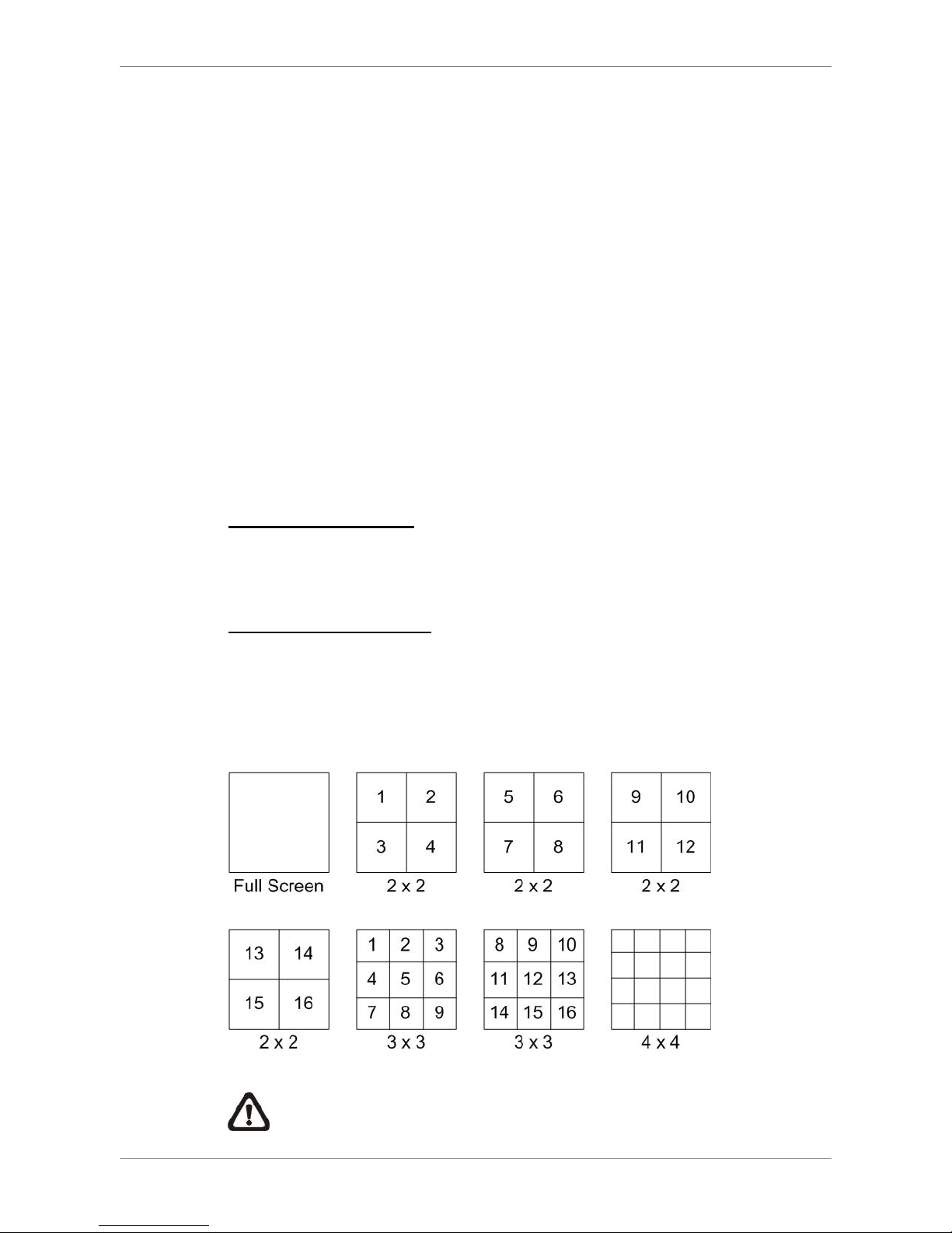
Viewing in Multi-window
Various multi-window view formats are offered for selection. To switch
between available viewing formats, press MODE repeatedly.
The available view formats are illustrated as the following figure.
NOTE: 3x3 viewing mode is only available in 8-ch and 16-ch models,
whereas 4x4 viewing mode is only available in 16-ch models.
Page 35

DVR User’s Manual
34
4.1.2 Digital Zoom
Users are able to view a 2× full screen in live mode. To view the 2× full
screen, follow the steps.
Press any CHANNEL key to view the corresponding camera in full screen.
Press ENTER to view 2× zoomed screen of the selected camera.
To view a specific area in 2× zoomed screen, use Direction keys to pan /
tilt the zoomed screen.
Either press ENTER again or ESC to leave the Zoom mode.
4.1.3 View Live Cameras
Users are allowed to view live camera in versatile viewing modes, including
full-screen, 2×2, 3x3 and 4×4. The general operation under live mode is
described as follows.
Freeze Live Image
Press FREEZE while viewing live image, the image pauses but the date /
time information does not, and the system clock continues running.
Press FREEZE to pause the live image; press FREEZE again to resume the
live camera view.
4.1.4 View Recorded Video
To view recorded video, users can press PLAY key directly. When press the
PLAY key, the unit starts to continue playing back the recorded video from the
suspended point of record. If it is the first time to use the PLAY key, the unit
will playback from the very beginning of the record. Alternatively, users can
select records from the Search menu to play specific video. Refer to section
Searching Recorded Video for more information.
NOTE: When playing back videos with mass motion recorded in D1
mode (resolution=720x480), press SEQ key to switch on “deflicker
function” to avoid gleaming of images. Press SEQ again to switch
“deflicker off” and the image will return to real D1 resolution.
Page 36

DVR User’s Manual
35
The Forward or Reverse speed indicator will be shown on the bottom-left
corner of the screen, when in the playback mode.
Page 37

DVR User’s Manual
36
The general operations in playback mode are described as follows.
Key Usage in Playback
The key usage is slightly different in playback mode. Following is the key
usage found in playback mode.
LEFT (Reverse Playback): The key is used to reverse the recorded video
while the unit is playing back. Press the key repeatedly to increase the
speed of reverse playback by 1×, 2×, 4×, 8×, 16×, or 32×.
RIGHT (Forward Playback): The key is used to play the recorded video
fast forward. Press the key repeatedly to increase the speed of forward
playback by 1×, 2×, 4×, 8×, 16×, or 32×.
FREEZE: Press FREEZE to pause the playback video. When the
recorded video is paused, press LEFT / RIGHT to resume playback video
single step reverse / forward, respectively. Press FREEZE again to
continue playing video.
PLAY: Press it to start playing back video, exit current mode, or stop
playing back video and return to live mode.
Pause Playback and Single Step Forward
To pause and resume recorded video, follow these steps.
Press any CHANNEL key to view the corresponding camera in full screen.
Press FREEZE to pause the current playback image.
Press LEFT / RIGHT Direction keys to move the video single step reverse
/ forward. Press and hold LEFT / RIGHT keys to repeatedly reverse /
forward the video single step.
Press FREEZE again to resume the playback operation.
4.1.5 Taking Snapshots
When a live or playback video of a single channel display is paused, users
can press ENTER key to capture and export snapshots to an external storage
device, excluding optical drives. Note that the system log will keep a record of
any snapshot exportation.
Page 38
DVR User’s Manual
37
4.2 Sequence
This section introduces the way to view sequence mode with both Main
Monitor and Call Monitor, if connected. Sequence function can avoid manual
backtracking and provides more flexibility while monitoring surveillance.
4.2.1 Sequence with Main Monitor
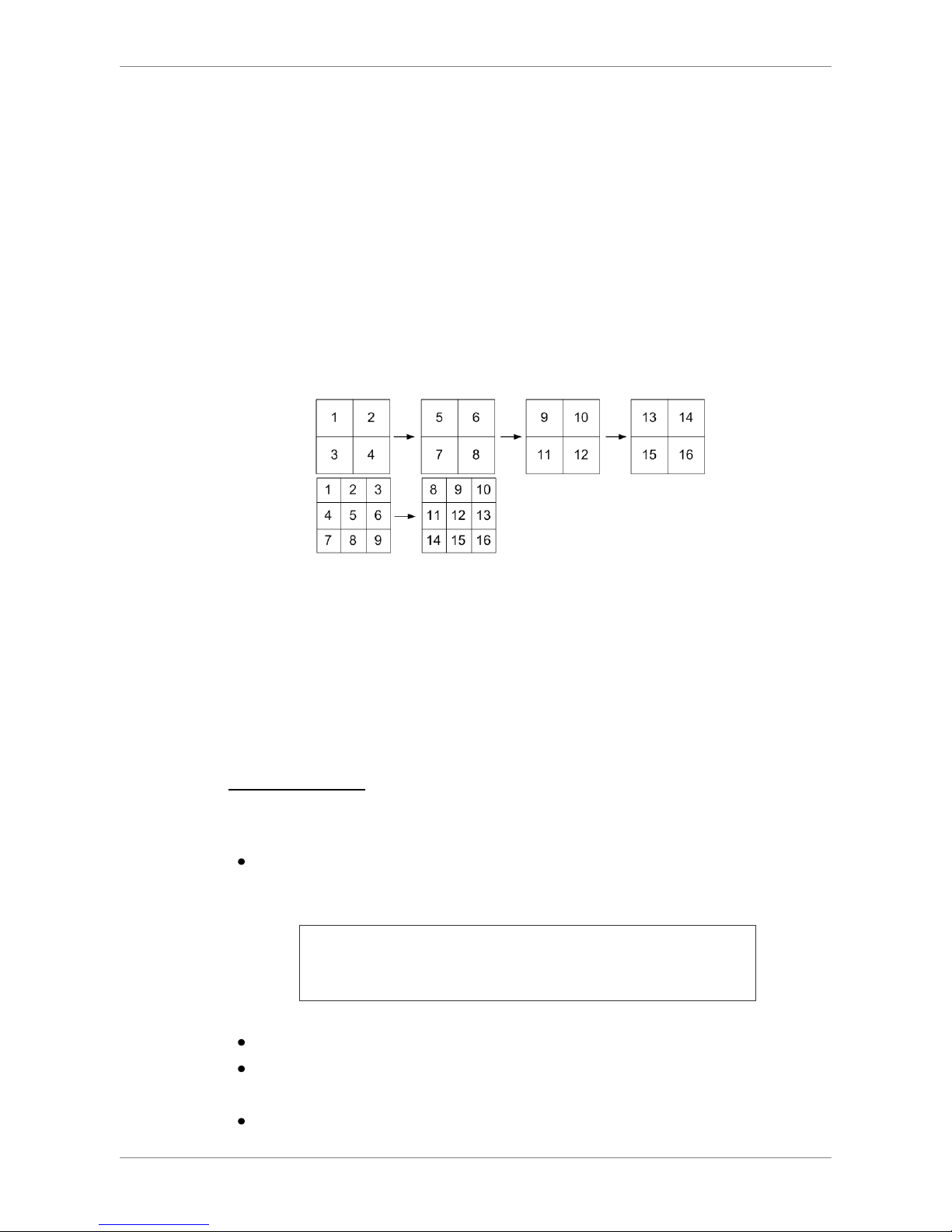
Automatic sequence function can be observed in any view mode. Select
certain view format and press SEQ to toggle the automatic sequence; press
ESC to stop sequencing. The figure below displays the 4-camera and
9-camera sequencing view modes.
4-camera:
9-camera:
(for 16ch models only)
4.2.2 Sequence with Call Monitor(8CH & 16CH models only)
Users are allowed to use the DVR front panel to control a call monitor display
without having to access the Main menu. Two viewing modes can be
displayed on call monitor: Sequence display and Single camera display. To
program the call monitor sequence, see OSD Setup Manual, Section
Sequence Setup.
Follow the steps to control the call monitor.
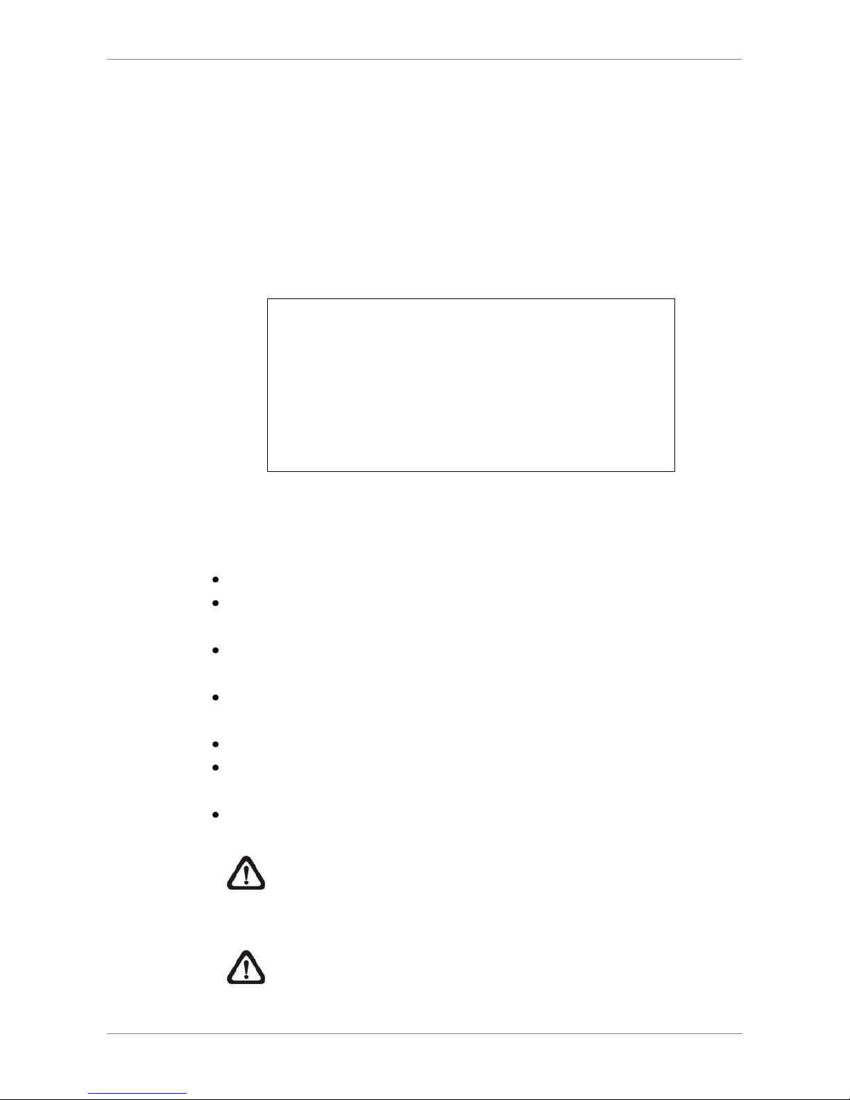
Press the CALL key on the front panel to enter Call Monitor Control mode.
The message “Call Mode” will be shown on the bottom-left of the screen.
Press 1-16 Key To Select Channel
Press SEQ To Enable Sequence
Call Mode
Press CHANNEL key to display the associated camera on call monitor.
Alternatively, press SEQ repeatedly to display the sequence of cameras
previously programmed in Call Monitor Schedule menu.
Press ESC to return the front panel to Main Monitor Control mode.
Page 39
DVR User’s Manual
38
4.3 Search Recorded Video
The DVR is capable of searching and playing back recorded video by time or
by events. To search by time, select a specific date and time of the wanted
video or enter Calendar Search. To search by event, select channels to
display the event list.
In live or playback mode, press SEARCH to enter the Search menu, shown
as below.
Search
----------------------------Search By Time----------------------------
From:
End:
Select:
2008/01/01 00:00:00
2008/05/01 00:00:00
2008/01/01 00:00:00
Begin Playback
Calendar Search
----------------------------Search By Event----------------------------
Select Channel:
CH1 CH2 CH3 CH4
Event List
4.3.1 Search by Time
Follow the steps to search video by date and time.
Press SEARCH to enter the Search menu.
Move the cursor to “From” and press ENTER will start playing recorded
video from the specified “From” time.
Move the cursor to “End” and press ENTER will start playing recorded
video from the specified “End” time.
Move the cursor to “Select” and press LEFT/RIGHT keys to choose date/
time. Press ENTER and adjust the values by UP/DOWN keys.
Press ENTER to confirm the settings or ESC to abort.
Move the cursor to <Begin Playback> and press ENTER to start playing
back the selected video.
Press PLAY again to return to live video.
NOTE: If there is no available recorded video that matches the
specified time and date, the unit starts playback from the next
available video.
NOTE: The date/time information will be shown on the screen with
a DST icon if the Daylight Saving Time function is enabled. “S”
indicates summer time and “W” indicates winter time.
Page 40
DVR User’s Manual
39
4.3.2 Calendar Search
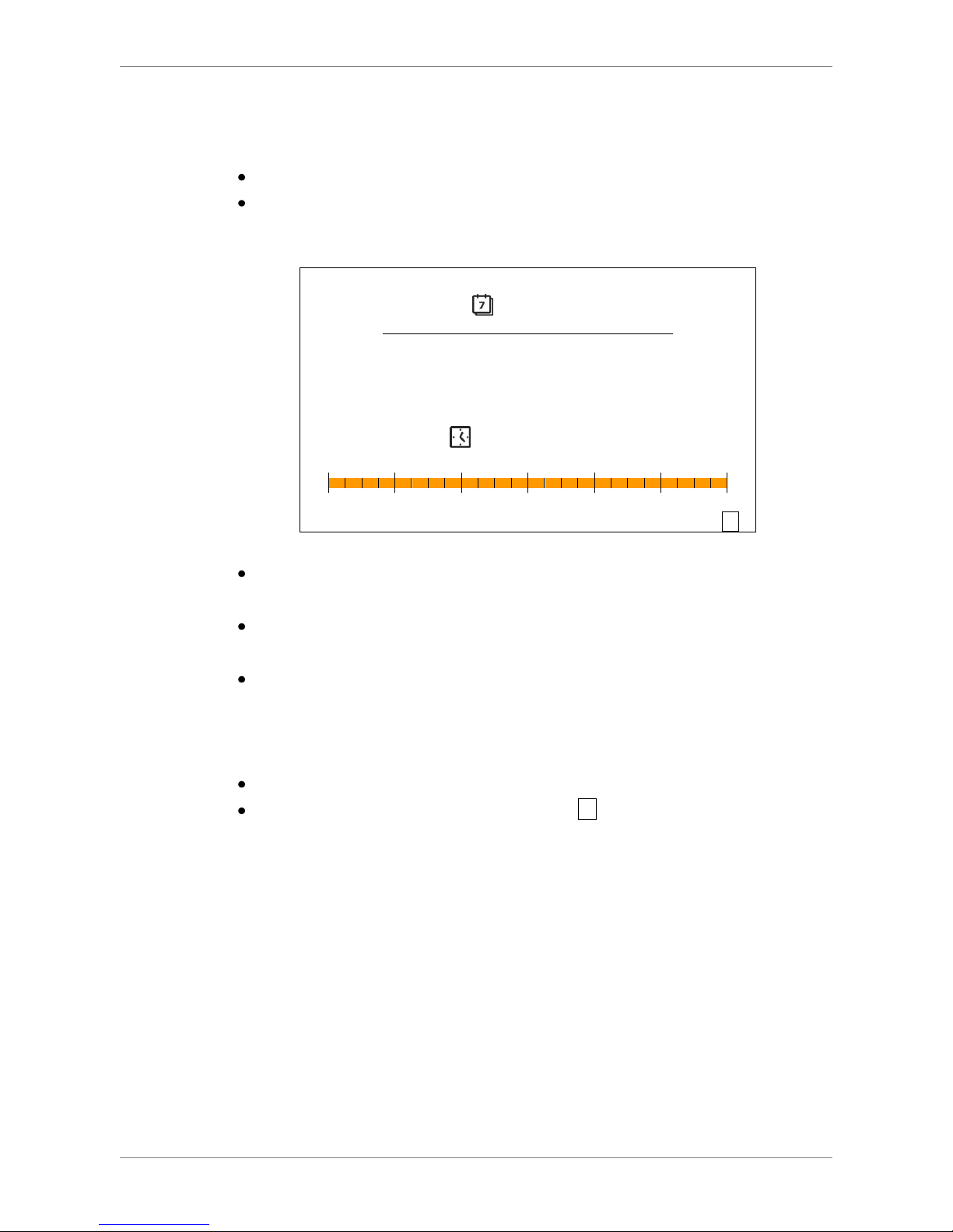
Follow the steps below to search recorded video via Calendar Search.
Press SEARCH button to enter the Search menu.
Move the cursor to <Calendar Search> and press ENTER. A calendar will
be shown as below.
Calendar Search
2009 / 03
S M T W T F S
1 2 3 4 5 6 7
8
9
10
11
12
13
14
15
16
17
18
19
20
21
22
23
24
25
26
27
28
29
30
31
---------------------
Search By Time
----------------------
↓
0 4 8 12 16 20 24
Select:
2009/03/13 PM06:03:02 ►
Move the cursor to year/ month and press ENTER. Then press
UP/DOWN keys to adjust the value and press ENTER again to confirm.
Move the cursor to select any day shown in bold font, and a time ruler will
be displayed.
Press ENTER and an arrow will show up above the time ruler. Press
LEFT/RIGHT keys to select a desired time. Alternatively, move the cursor
to the time shown at the bottom. Press ENTER and adjust the values of
hour/ minute/ second via UP/DOWN keys.
Note that the time blocks highlighted in red represent events occurred.
Move the cursor to the playback icon (►) and press ENTER to start
playing back the video.
Page 41

DVR User’s Manual
40
4.3.3 Search by Event
“Event List” allows users to search wanted video by event. The Event List is
displayed as below figure:
Event List
First Page
Date Time
2008/03/17 11:26:50
2008/03/17 09:53:03
2008/03/16 16:14:42
2008/03/15 03:45:31
2008/03/12 22:27:56
2008/03/12 10:09:29
2008/03/11 12:18:20
2008/03/10 05:16:00
2008/03/08 17:11:37
2008/03/08 16:29:10
2008/03/08 03:22:17
Ch.
2
5
3
1
1
7
6
4
2
8
2
Type
Motion
Alarm
Alarm
Motion
Alarm
Motion
Motion
Alarm
Motion
Motion
Alarm
The list displays events by date, time, triggered camera and alarm type. As
some events are deleted, others are displayed. The latest recorded event
video will be listed on the top.
Follow these steps to search event video through Event List:
Press SEARCH to enter the Search menu.
To search event video that has been recorded on a specific camera, use
LEFT / RIGHT to move the cursor and press ENTER to select or de-select
a channel.
Move the cursor to <Event List> and press ENTER to list the event video
of the selected channels. The Event List displays.
To exit the event list, press ESC.
Follow the steps to playback video from Event List.
Press and hold UP / DOWN to scroll through the Event List.
Press ENTER to play back the selected event record.
Press PLAY to return to live mode.
Page 42
DVR User’s Manual
41
4.4 Video Export
The unit allows users to export wanted video to the built-in DVD+RW or an
external device, such as a USB ThumbDrive, and the exported video will be
saved as *.drv file. Note that the system log will keep records of all video
exportations, including duration, start time, and end time.
If the video is to be exported to an external device, make sure the device is
connected to the DVR unit and the port has been set appropriately for video
export.
NOTE: Once an external device is connected to the DVR unit, the
device has priority over the built-in DVD+RW. That means the video
will be exported to the external device instead of the built-in DVD+RW.
According to the size of video, the export may take about 10 minutes to 1
hour.
4.4.1 ezBurn Introduction
Built with the ezBurn technology, ezBurn function provides users the easier
way to export desired video with built-in DVD+RW or to an external device,
such as an USB ThumbDrive®.
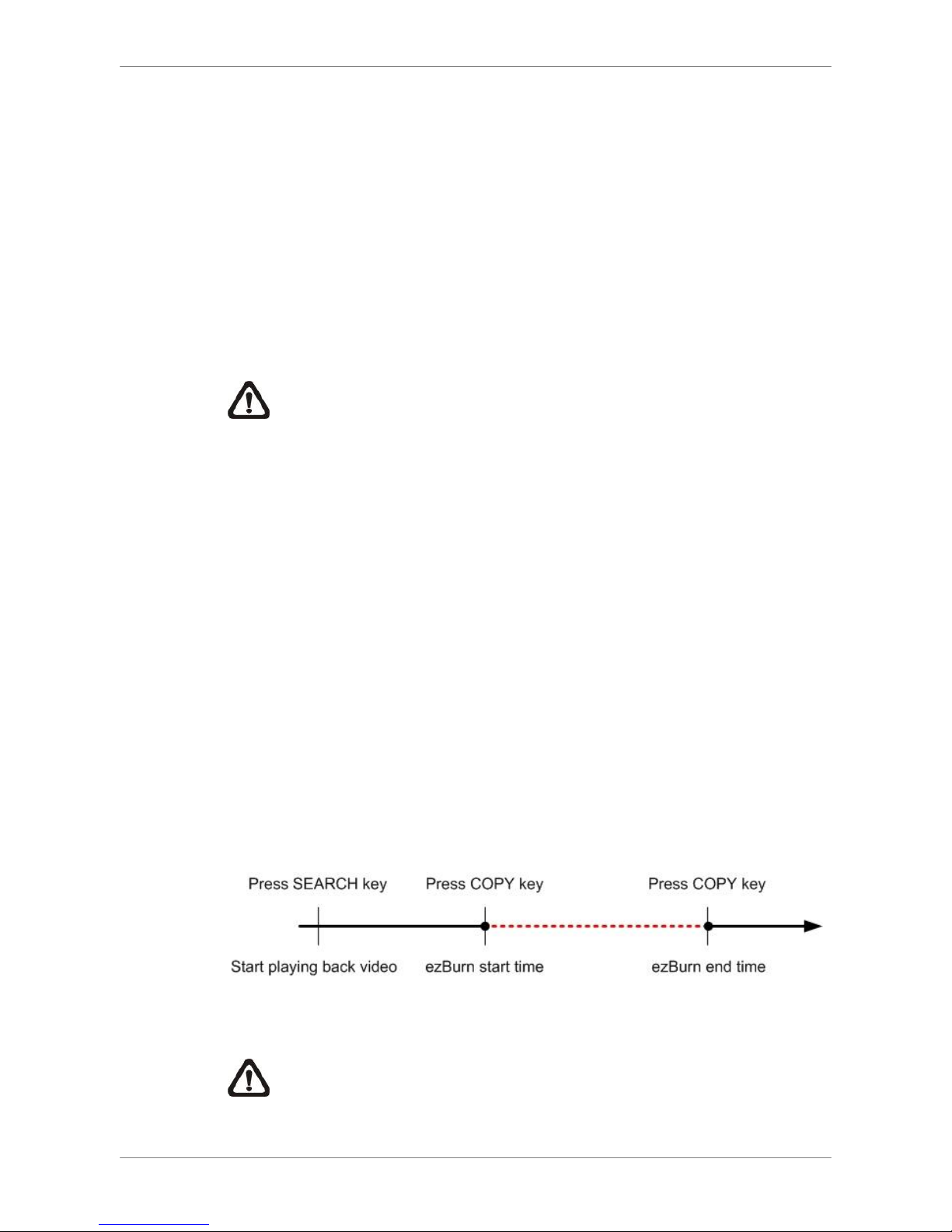
TWO keys (SEARCH and COPY) and THREE touches are all what’s needed
for completing the export. The entire exporting process will be done through
the front panel, without needing to enter the OSD setup menu.
The ezBurn exporting process is illustrated as below figure:
The entire process is described step by step in the following sections.
NOTE: The file exported using ezBurn will be in .drv file format, and it
can only be played using the remote player software.
Page 43
DVR User’s Manual
42
4.4.2 Export Normal Video
To Export normal video to external device, follow these step:
Press SEARCH and play wanted normal video by entering date and time.
Note if the screen is showing in multiple channel mode, please make sure
there is no window displaying in Live mode, or the export will not work.
After entering playback mode, play the video and press COPY once to
mark the starting point of the export video. The playback continues.
Press COPY again to mark the ending point of the export video. Then the
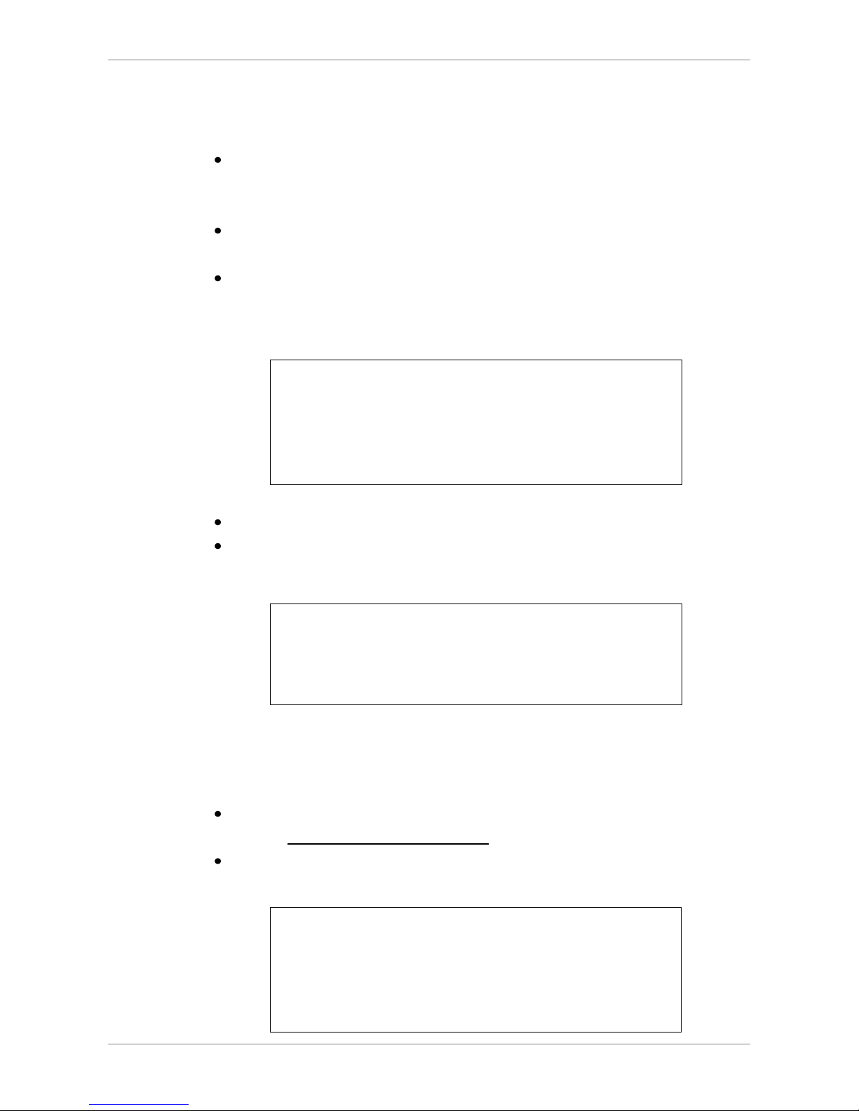
“ezBurn” window will display as below figure. The information shown on
the window is “read only”.
ezBurn confirmation
Selected Device: USB Storage Device
Exported Required Size = 11 MB
Real Export Range:
From: 2008/06/07 AM10:41:13
To: 2008/06/07 AM10:41:21
Enter: YES ESC: NO
Press ENTER to start the export; or, press ESC to abort.
If there is no any exportable device connected to the DVR unit, then a
warning message will be shown on the screen, as below figure:
No exportable device detected.
Please install the target device/media
to the DVR.
Enter: Retry ESC: Exit
4.4.3 Export Event Video
To export event video, follow these steps:
Press SEARCH and play wanted event video. To play event video, refer to
Section Searching Recorded Video.
After entering the playback mode, press COPY. The “ezBurn” window will
display as below figure. The information shown is “read only”.
ezBurn confirmation
Selected Device: USB Storage Device
Exported Required Size = 11 MB
Export Event Info:
Data
Time
Ch
Type
2008/06/07
AM10:42:35
13
Motion
Enter: YES ESC: NO
Page 44

DVR User’s Manual
43
If there is no any exportable device connected to the DVR unit, a warning
message will be shown on the screen
Press ENTER to start the export the whole event video to the connected
device; or, press ESC to abort.
4.5 Dome Control
The DVR allows users to control a dome camera by the front panel. In Live
mode, users can press CHANNEL key to display the desired dome camera in
full screen. To enter Dome Control mode, press the DOME key and press
channel key 2 to display the hint screen. To exit the Dome Control mode and
return to live mode, press ESC or DOME.
In dome control mode, press CALL + ENTER to open the OSD setup menu of
the dome camera. To traverse the menu, press CALL + UP/DOWN keys to
move up/down, CALL + RIGHT/LEFT to change value or to move left/right,
and CALL + ENTER to select or enter submenu.
4.5.1 Dome Connection
Follow the steps to install dome cameras.
See Setup Guide for RS-485 port pin definition.
Connect the R+, R- terminals on the dome camera to the D+, D- terminals
on the RS-485 port by RS-485 cable respectively. Refer to the connection
figure illustrated in Setup Guide.
4.5.2 Dome Protocol Setup
The Dome Protocol item lists the available dome protocols for communicating
with dome cameras connected to the DVR. From the Main menu, select
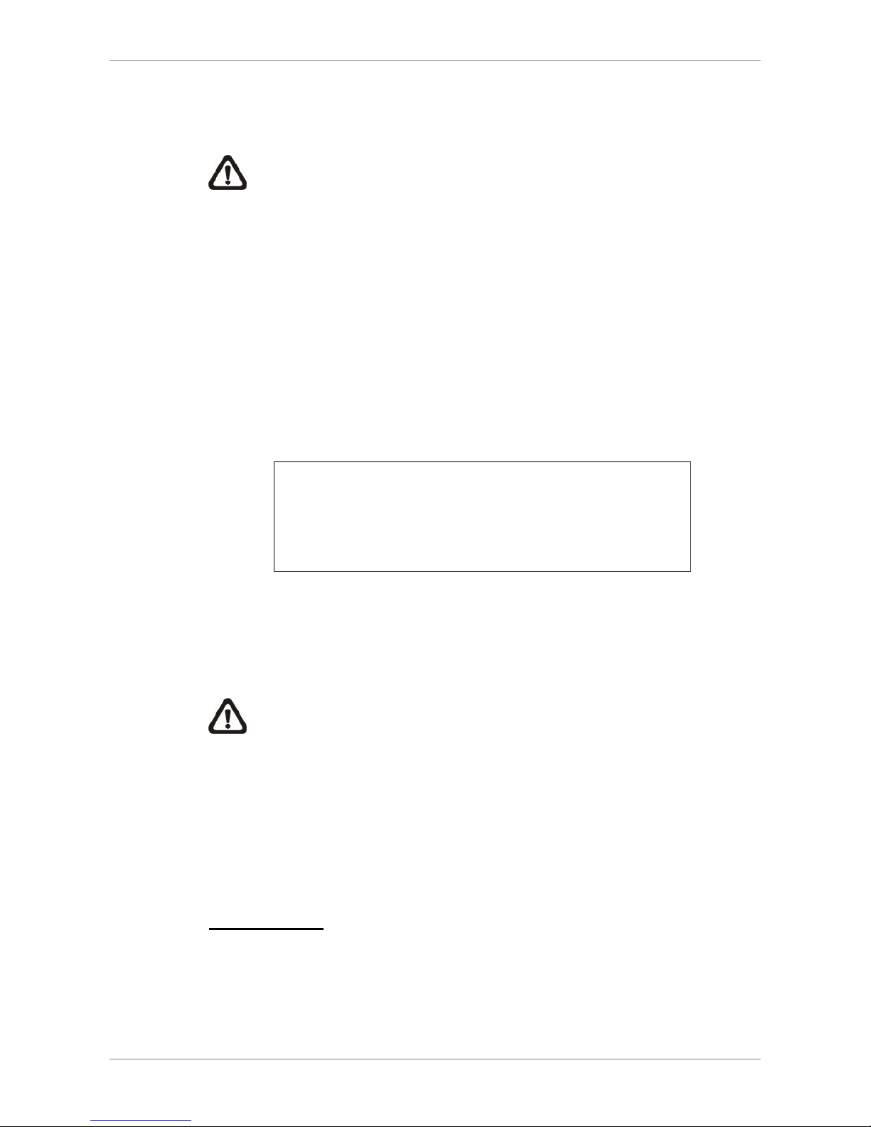
<Camera Setup> and press ENTER. The following menu is displayed.
Analog Camera
Analog Camera Select
Dome Protocol
Dome ID
Camera Title
Covert
Brightness
Contrast
Saturation
Hue
Audio Association
CH1
None
0
No
0
0
0
0
Yes
Page 45
DVR User’s Manual
44
To configure dome protocol, select a camera first and set the communications
protocol associated with dome camera using the Direction keys and ENTER.
NOTE: The settings become effective after saving the changes and
exiting from the menu.
4.5.3 RS485 Setup
The DVR controls the domes via RS-485 communication protocol. The
RS-485 parameters in the DVR must be set to the same parameters set in
dome camera.
Users are allowed to change the RS-485 settings of the DVR. Select
<System Setup> in Main menu, then select <RS485 Setup> from the System
Setup menu and press ENTER. The following menu is displayed.
RS485 Setup
Unit ID
Baud Rate
Bits
Stop
Parity
224
9600
8
1
None
The ID number must match the ID address set by the dome. The Unit ID is in
the range of 1 to 255. Note that there cannot be any two devices on the same
bus given the same ID address, or a conflict may occur.
NOTE: The settings become effective after saving the changes and
exiting from the menu.
4.5.4 Dome Controlling Keys
The functions of some keys in Dome Control mode are totally different from
normal status function. Please refer to Setup Guide for the graphical
illustration of functional keys.
Set / Go Preset
This key is used to enter the Dome Preset menu to set up certain position as
a preset and go to the predetermined preset positions for viewing.
Page 46

DVR User’s Manual
45
Toggle Hint Screen
This function is used to avoid viewing the dome parameter information while
controlling dome cameras. Press this key to hide the screen. Press it again to
redisplay the screen.
Iris Open
Use to open the Iris on the dome camera.
Focus Near
Use to focus the dome camera near.
Zoom In
Use to zoom in the dome camera. This function enables users to enlarge a
certain area.
ESC
Use to leave Dome Control mode and return to live and full-screen viewing
mode.
Auto / Enter
In OSD setup menu interface, the key is used to make selection.
In Dome Control mode, this key is used to activate automatic focus and
iris function.
Iris Close
Use to close the Iris on the dome camera.
Focus Far
Use to focus the selected dome camera far.
Zoom Out
Use to zoom out the dome camera. This function enables users to shrink the
current image and view a larger area.
Pan / Tilt
Use to pan and tilt dome camera.
Page 47
DVR User’s Manual
46
4.5.5 Setting Preset Points
The DVR allows users to set preset positions. The amount of preset points
depends on the dome manufacturer.
Follow the steps to set preset points.
Press a Channel key to view the corresponding camera in full screen.
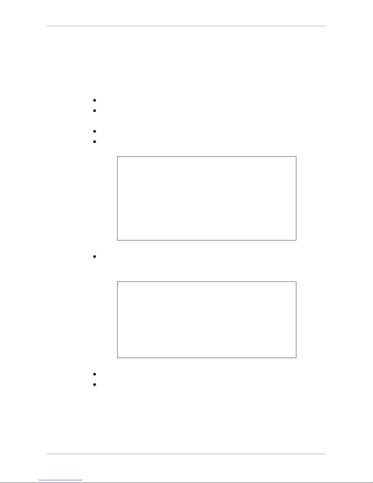
Then press DOME to enter Dome Control mode. A Hint Screen shown as
below figure displays on the screen.
Press 2 to hide the Hint Screen; press 2 again to toggle the Hint Screen.
Use Direction keys to position the dome camera to desired position.
Hint Screen
DOME / ESC: Exit
MODE / PLAY: Iris Open / Close
SEQ / FREEZE: Focus Near / Far
MENU / SEARCH: Zoom In / Out
ENTER: Auto Focus / Iris
◄▲▼►: Pan / Tilt
CH1: Set / Go Preset
CH2: Hint Screen On / Off
Dome Control
Press 1 to access the Set/Go Preset function. The Dome Preset menu is
displayed.
Dome Preset
First Page
Index
1
2
3
4
5
6
7
Set Preset
No
No
No
No
No
No
No
Go Preset
No
No
No
No
No
No
No
Use UP / DOWN keys to select the desired preset number from the menu.
Set the <Set Preset> of the selected preset number to <Yes>, and press
ENTER to save the position. Now the preset is set and ready to be called.
Page 48
DVR User’s Manual
47
4.5.6 Calling Preset Points
Follow the steps to call preset points.
Press a Channel key to view the corresponding camera in full screen.
Then press DOME to enter Dome Control mode. A Hint Screen will be
displayed on the screen.
Press 2 to hide or display the Dome Control Hint Screen.
Press 1 to access the Set/Go Preset function.
Dome Preset
First Page
Index
1
2
3
4
5
6
7
Set Preset
No
No
No
No
No
No
No
Go Preset
No
No
No
No
No
No
No
Use UP / DOWN keys to select the desired preset number from the menu.
Set the <Go Preset> of the selected preset number to <Yes>, and press
ENTER to call the preset point.
The selected dome camera will rotate to the preset position automatically.
4.6 System Log Exportation
In the Configuration setup menu, select <Boot Log> and a list of system logs
will be displayed on the screen. Users can export the system log as a data file
to an external storage device. Connect a USB storage device and press
COPY to export the system log file to the USB storage device. Note that in
the mean time, a digital signature file will also be exported.
Configuration
Load Factory Default
Import Config
Export Config
Boot Log
Operation Log
No
Off
Also under the Configuration setup menu, set <Operation Log> to <On> and
operation logs will start to be recorded in the system log. Alternatively, set to
<Off> and operation logs will not be part of the system log.
Page 49
DVR User’s Manual
48
5. Remote Monitoring Software
The remote monitoring software is a remote browser-based software
application designed to operate with the DVR products. Using the software,
users are allowed to view live and recorded video, and configure the DVRs
remotely via a LAN, WAN or Internet on a personal computer.
The connected PC will automatically download the remote monitoring
software plug-ins from the DVR when the DVR is connected by entering its IP
address in the address bar on the browser.
Due to the setting items are similar to those listed in the DVR’s OSD setup
menu, please refer to the sections above for setting configuration of the
remote monitoring software.
The tasks can be performed with the remote monitoring software are listed
below:
Remote viewing of live/ recorded video
Remote setup of the DVR
Remote control of dome cameras
Alarm notification from the DVR
Up to three connections to one DVR using the remote monitoring software,
including the preset “admin” and two other accounts
5.1 Remote Monitoring System Requirements
Items
Minimum Requirements
Personal Computer
Minimum:
Intel® Pentium® M CPU 1.40GHz
RAM 512 MB
Recommended:
Intel® Core™2 Quad CPU Q6600 @ 2.4GHZ
RAM 2 GB
Hard Disk Drive
Requires 20 MB for software installation
Operating System
Windows XP, Windows Vista
Web Browser
Microsoft Internet Explorer version 6.0 or above
Monitor Resolution
Minimum 1024 x 768 with 16-bit color
Network Card
10Base-T (10 Mbps) or 100Base-TX (100 Mbps)
operation; must match the network configuration
Page 50
DVR User’s Manual
49
5.2 Installation of Software
Refer to the following description to install the remote monitoring software.
5.2.1 Change Internet Settings
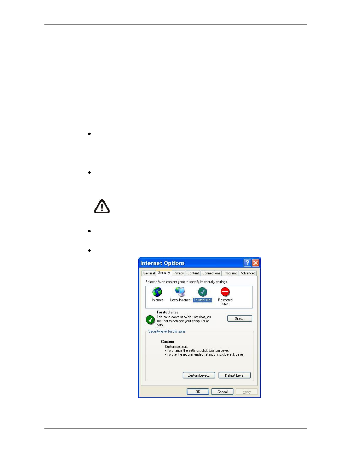
The PC operating with the remote monitoring software should be set to
accept ActiveX plug-ins. Please follow the steps to set the Internet security
settings appropriately.
Before operating the remote monitoring software, please check the IP
address of the DVR. To check the IP address, press MENU key on the
unit and enter password to access OSD setup menu. Select <System
Setup>, <Network Setup>, then <LAN Setup> to check the IP.
Start the IE; it can be started either by clicking on the desktop icon, or by
using the Start menu to access it.
NOTE: Windows IE provides the ActiveX component that is
required when using the remote monitoring software.
Select <Tools> from the main menu of the browser, then <Internet
Options>, and then click the <Security> tab.
Select <Trusted sites> and click <Sites> to specify its security setting.
Page 51
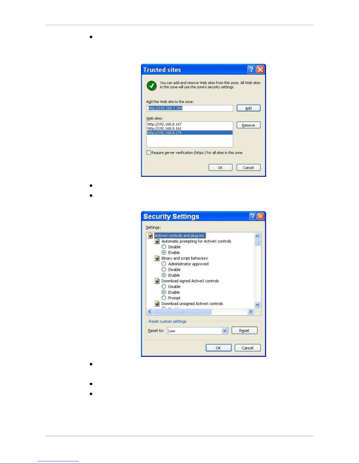
DVR User’s Manual
50
Uncheck “Require server verification (https:) for all sites in this zone”.
Type the IP address of the unit in field and click <Add> to add this web site
to the zone.
Click <OK> to confirm the setting and close Trusted sites dialog.
In the Security Level area, click <Custom Level>. The Security Settings
screen is displayed.
Under <ActiveX controls and plug-ins>, set all items to <Enable> or
<Prompt>.
Click <OK> to apply the setting and close the <Security Settings> screen.
Click <OK> to close Internet Options dialog.
Now the installation can continue to the next step.
Page 52
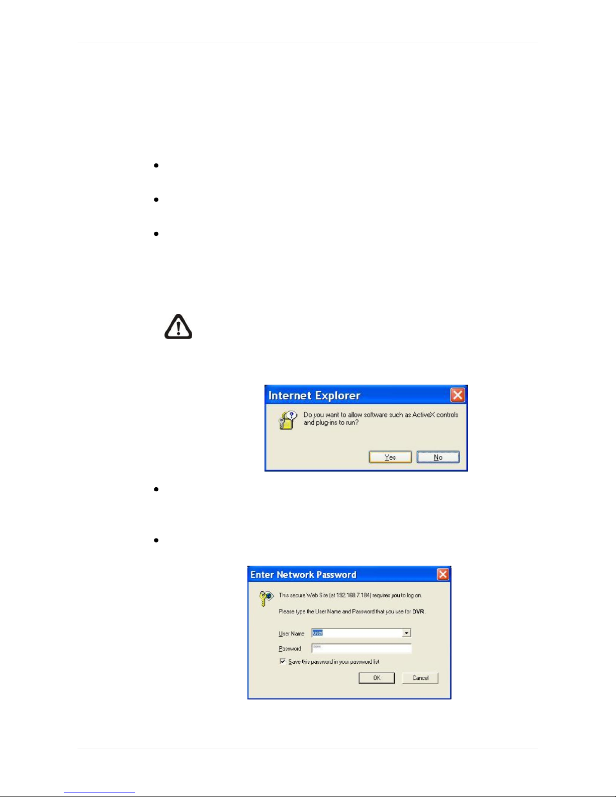
DVR User’s Manual
51
5.2.2 Install the Remote Monitoring Software
Start the browser to initiate the installation of the remote monitoring software
on the PC. The IP address of the DVR can be saved as a Favorites item in
the web browser to enable easy access in the future.
Start the IE; it can be started either by clicking on the desktop icon, or by
using the Start menu to access it.
Enter the IP address of the DVR in the address bar at the top of the
browser.
The ActiveX controls and plug-ins dialog will show twice for confirmation;
click <Yes> to accept ActiveX plug-ins. The remote monitoring software
plug-ins will be downloaded and installed on the PC automatically when
the connection is successfully made.
NOTE: Do not enter any leading “0” characters in the address, for
example, “192.068.080.006” should be entered as “192.68.80.6”. If
the default trigger port 80 is changed into another one, take port 81
for example, the IP address should be entered as “192.68.80.6:81”.
A version check starts to verify whether the remote monitoring software
was installed already, and also check if the version is the same as that
stored in that particular DVR. This process may take up to 30 seconds.
When the software is completely downloaded and installed, the Login
Screen is now displayed.
Page 53
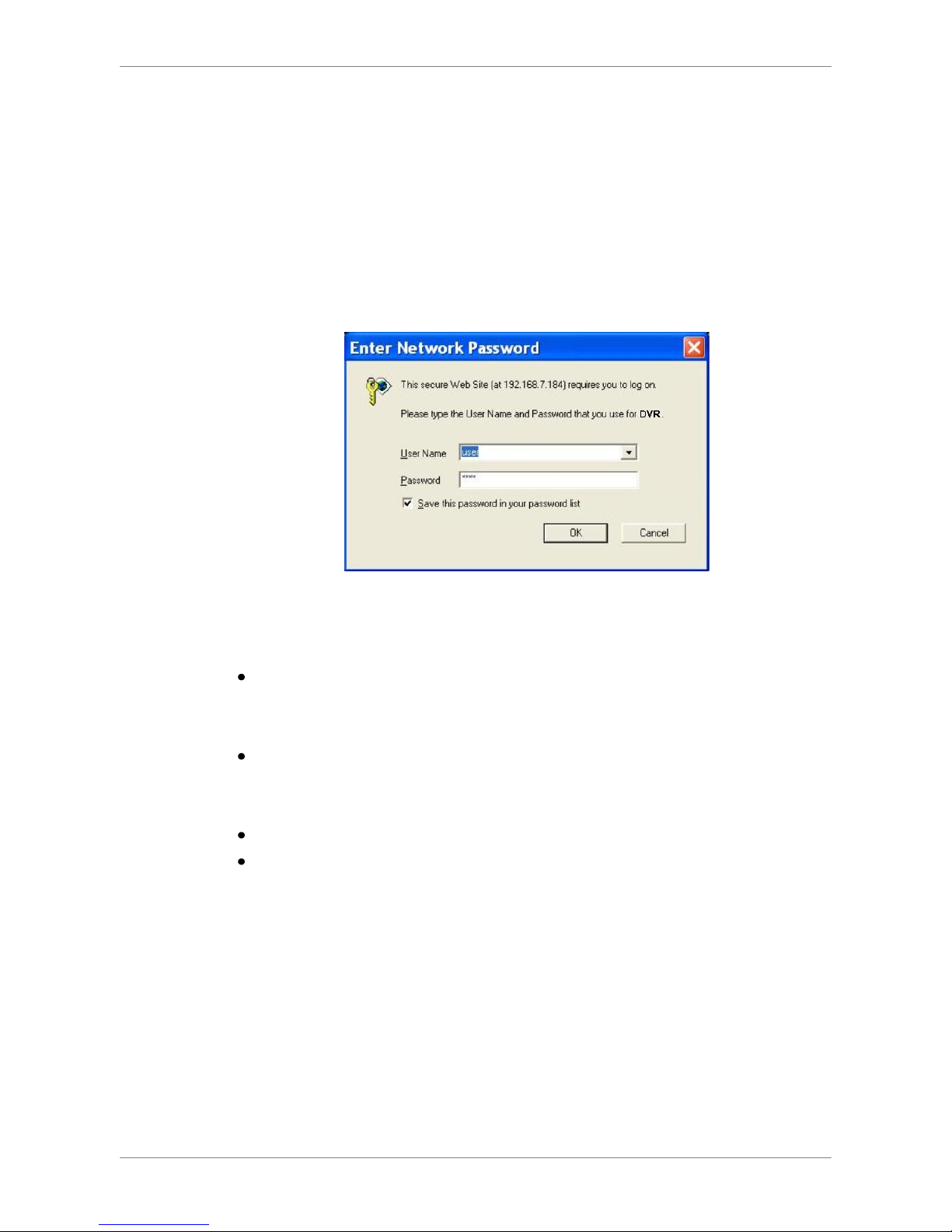
DVR User’s Manual
52
5.2.2.1 Login / Logout
Login using the same accounts setup in the DVR. The authority is also the
same as setup in the DVR.
One preset account “admin” and up to two other accounts can access a DVR
at the same time. Nevertheless, if the “admin” account is currently accessing
the unit’s OSD setup menu via front panel of the unit, then the “admin”
account at the remote monitoring site cannot change the settings at the same
time. The “admin” account of the DVR has priority.
The following steps demonstrate procedures to view video from remote unit:
Start the remote monitoring software by entering the IP Address of the
DVR in the Address bar of the browser. Alternatively, click on the Favorite
entry for the unit (if the IP address of the unit has been set).
Enter the Username and password. The login username and password
can be saved to ease future login. The default username and password is
admin / 1234.
Click <OK> to login to the DVR. The process may take a few seconds.
If the connection is made successfully, the main window will display live
video of the attached cameras.
If the IE browser is closed, the remote system is logout and disconnected
from the DVR at the same time.
Page 54
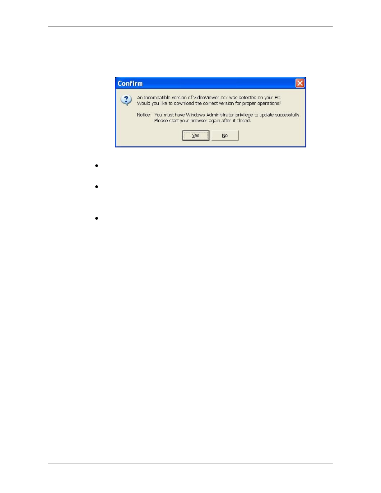
DVR User’s Manual
53
5.2.2.2 Software Upgrades
If a new version of the remote monitoring software is available on the DVR,
upgrade will be prompted while accessing the unit. Follow the steps to
upgrade the software.
The message as the above figure will be prompted. Click <Yes> to accept
version upgrade.
Start the IE again and enter the IP address of the DVR in the Address bar
of the browser; or if the unit address is set as a Favorite site, click the
Favorites entry for the unit.
When the software is completely downloaded and installed, the Login
Screen will be displayed.
5.3 Basic Operation
When a DVR is successfully connected, the main window of the remote
monitoring software will be displayed. Please refer to the Setup Guide for the
graphical illustration of functional items.
The functions on the remote monitoring software will be described in the
following sections.
5.3.1 View Live Video
View live video from the cameras attached to the DVR by clicking <Live>
button on the main window toolbar. Choose desired display mode –
full-screen, 2x2 windows, 3x3 windows, and 4x4 windows – after the live
images of the DVR are displayed on the main window. When a dome camera
is connected and viewed in single channel full-screen mode, the dome
camera control operation can be accessed. To choose desired display mode
and to operate dome camera control, refer to the following sections.
Page 55

DVR User’s Manual
54
5.3.1.1 Select Display Mode
Choose the number of windows to be displayed on the main window. Click
one of the display buttons in MODE section. Available selections are 4, 9 and
16 camera displays. To view certain window in full screen, either double-click
on the wanted window, or click on the corresponding CAMERA button.
5.3.1.2 Operating Cameras with Dome Control
The remote monitoring software allows users to control and configure a dome
camera remotely.
Click on any CAMERA button displayed with a dome icon to view the camera
in full screen. The Dome Control Panel will be displayed on the main window.
The items on the dome control panel are described as follows.
Set Preset (•)
Set Preset is used to set up preset positions. The remote monitoring software
allows its user to set up to 255 preset positions according to the allowance of
the supported dome cameras.
Use Direction buttons to move dome camera to an appropriate position, and
then click the button and choose wanted number from the pull-down list. The
preset position is named as the selected number.
Go Preset (•)
Go Preset is used to call the camera preset point, which was set up with the
set preset point function. Click and choose a number to call the preset point
for viewing.
Auto Focus (A.F.)
Click on it and the focus of the camera will be automatically adjusted to show
a clearer image.
Dome ID (ID)
Click for changing the dome ID and protocol. Proper authority is required to
access this function.
Page 56
DVR User’s Manual
55
Focus +/−
Use to adjust the camera lens to focus on objects for a clear view. Click on
<Focus +> to focus near or <Focus −> to focus far.
Iris +/−
This item is used to open and close the iris to let more or less light into the
camera. Click on <Iris +> to open iris or <Iris −> to close iris.
Zoom +/−
Users are allowed to zoom-in or zoom-out using the adjusting buttons.
Zoom-in to enlarge a certain area and zoom-out to view more area.
Direction Button
This button is used to pan and/or tilt the dome camera. Click the arrows in the
directions to be viewed.
5.3.2 Instant Recording
The Instant Recording function allows users to record video quickly to the PC.
NOTE: The Audio function is set to OFF as the default setting.
5.3.2.1 Record Video Instantly
Follow the steps to start recording instantly:
Click on the <Instant Recording> button.
Select the destination folder to save the video.
Click on the button again to stop recording.
NOTE: The instant recording video will be saved as *.drv file.
5.3.2.2 Playback Instant Recorded Video
Follow the steps to playback a video recorded by “Instant Recording”.
Click <Play> on main window toolbar and click <Local Playback> tab.
Click <Open> to choose a recorded file.
Click <OK> to start playing the recorded video.
Page 57

DVR User’s Manual
56
5.3.3 Playback Video
The remote monitoring software allows users to view recorded video either
from the DVR, or from the hard disk drive of the PC
To access the Playback screen, click <Play> button on the main window
toolbar. There are three tabs in the Playback screen: <Remote Playback>,
<Local Playback>, and <Verify> tabs. <Remote Playback> allows users to
play back from the DVR. <Local Playback> enables users to playback a
recorded video file stored on the hard disk drive of the PC. <Verify> is
provided for users to authenticate if the exported video is altered.
The DVR continues recording while playing back recorded video on the PC,
either remote playback or local playback.
5.3.3.1 Playback Remote Video
To view remote video, click <Play> on the main window toolbar, and then
<Remote Playback> tab. The <Remote Playback> screen will be displayed.
The <From> and <To> in the <Available Record Video> display the date and
time from which recorded video is available for playback.
To playback remote video segments, follow these steps:
Choose <Playback> in <Select> field for playback recorded video.
In <Start> field, users can change the date and time either by typing
desired numbers directly or using the arrow buttons.
To type directly:
Click on day, month and year of date field respectively, and type the
desired numbers directly. Follow above steps to adjust the hour, minute
and second of time field.
To use the arrow buttons:
Click on the arrow button next to the date field to display the calendar; then
click the left and right arrow at the top of the calendar to change the date.
Use up and down arrow next to the time field to change to the wanted time.
The other way to select date and time is by moving the blue sliding bar.
Click <OK> to start the playback, or click <Close> to abort.
Page 58

DVR User’s Manual
57
The other option <Download (.DRV)> in <Select> field enables users to
download the video segment of selected date and time to the PC. The
selection of time duration is the same as described above. Files
downloaded will be in *.drv format.
5.3.3.2 Playback Local *.drv Files
The <Local Playback> tab allows users to playback *.drv video files stored in
the PC's hard drive.
Follow below steps to playback a downloaded *.drv file with the remote
monitoring software.
Click <Open> and the file selection screen is displayed.
Select the *.drv video file for playback and click <OK>.
Click <OK> in the <Local Playback> Screen to start the playback, or click
<Cancel> to abort.
View the video playback using the Playback controls.
To end the playback, click <Live> to return to live video.
5.3.3.3 Playback Controls
When the local or remote video is being played, the remote monitoring
software is in Playback Mode. The playback controls toolbar will emerge on
the main window toolbar. The Playback controls and indicators are described
as below.
Icon
Name
Description
◄◄
Fast Backward /
Step Backward
1. Click to play the recorded video in backward
direction. Click repeatedly to select the
backward playback speed: 1×, 2×, 4×, 8×, 16
×, or 32×.
2. When playback is paused, click repeatedly to
move backward step-by-step.
► / ▌▌
Play / Pause
1. While playing, click to pause the playback.
2. When paused, click to resume the playback.
►►
Fast Forward /
Step Forward
1. Click to play the recorded video in forward
direction. Click repeatedly to select the
forward playback speed: 1×, 2×, 4×, 8×, 16×,
Page 59

DVR User’s Manual
58
or 32×.
2. When playback is paused, click repeatedly to
move forward step-by-step.
Page 60

DVR User’s Manual
59
5.3.4 Verify Digital Signature
The digital signature aims to authenticate a video file exported from the unit.
Follow the description to verify the digital signature.
Click <Play> on the main window toolbar.
Click <Verify> tab to display the Verify window.
Click <Browse> to select the *.gpg, *.avi, *.sig files respectively, which
belong to the exported video to be authenticated.
Click <Verify> to start verifying digital signature.
The result of verify shows in the <Status Log> field. It returns a GOOD or
BAD signature result. A GOOD signature indicates the exported clip has
not been altered.
5.3.5 Search from Event List
Click SEARCH, the Event List appears. The List contains information about
the alarm events that the unit recorded and saved. Up to 1024 events can be
listed in the Event List.
The Event List displays each event by its number, the date and time of the
event, the type of the event (including Alarm In, Motion Detection, Video Loss,
and Over Speed), and the camera channel where the event occurred.
To view an event video, follow these steps:
Click SEARCH button positioned in the main window toolbar. The Event
List appears.
Scroll through the Event List and highlight the interested events.
Double-click on the desired event to view the event video.
5.3.6 Take a Snapshot
Snapshot is a simple screen capture tool. When users click on the
SNAPSHOT button, it will capture the screenshot of the window that is
currently showing on the screen. Each click captures one screenshot to be
saved as a JPEG file on the desktop. The snapshot file will be named as
“Snapshot-*”.
Page 61
DVR User’s Manual
60
5.3.7 Health Status
This function verifies the HDD status of the DVR. The information items in the
status chart are described as below.
Device Name
This item shows the model name of the HDD.
Int./Ext.
This item indicates whether the HDD is an internal or external device.
Total Size
This item indicates the total size of the HDD.
State
This item indicates whether the HDD is active or non-active.
Temperature
This information item is currently not available.
5.3.8 Normal and Dual Streaming
For different networks with different bandwidths, two streaming options are
provided – normal or dual streaming. The preset is normal streaming.
Users who are using high-speed networks, normal streaming will be a
recommended choice. Depending on the HDD capacity and network usage,
set the remote monitoring software to occupy high or low bandwidths.
For networks with limited bandwidth, dual streaming will be a better choice. It
enables coexistence of high quality streaming at local DVR site and lower
quality streaming but faster transmission for the remote monitoring site. To
select dual streaming, click on the bandwidth icon and the icon will change
color. Then users can furthermore choose different bit rates to adjust for the
best displaying quality.
NOTE: Dual streaming will only be available when the total PPS is set
to one-half of the max PPS, for example, set 30PPS for D1 recording.
The reserved half of the max PPS will be handling the low rate
streaming for transmission to the remote monitoring site.
Page 62
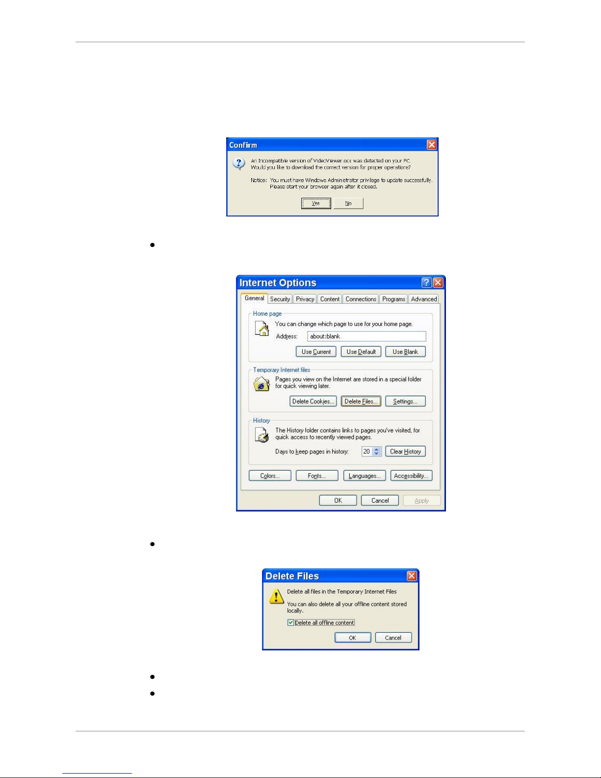
DVR User’s Manual
61
5.3.9 Remote Monitoring Software Trouble Shooting Guide
What happened if the server requests to upgrade the software every time the
DVR is connected? If the following screen displays repeatedly, please follow
the steps to delete the temporary internet files.
Select <Tools> from the main menu of the web browser, then <Internet
Options>, and then click the <General> tab.
Click the <Delete Files> button in the <Temporary Internet Files> field; the
<Delete Files> screen displays as below.
Check the <Delete all offline content> box and click <OK>.
Now, enter the IP address of the DVR to make the connection again.
Page 63
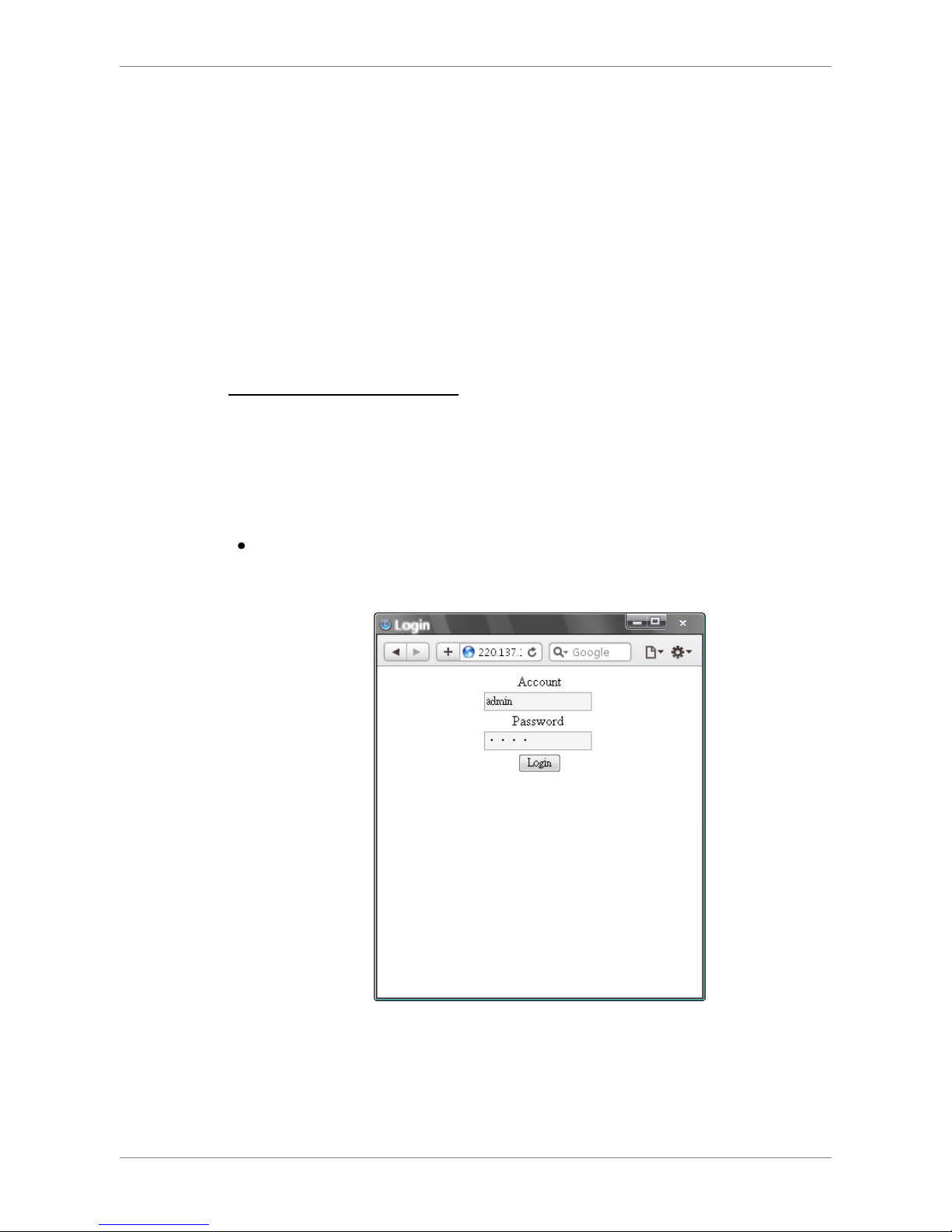
DVR User’s Manual
62
6. iPhone and Smart Phone Monitoring
The DVR also supports iPhone and smart phone monitoring. With the Safari
browser on iPhone and any JavaScript-based browsers (Firefox, Opera, or
Chrome) on smart phones, users can connect to the DVR via internet to
check out the live video of any selected single channel of the DVR at anytime
anywhere.
The live video will be MJPEG format with 1PPS per channel for all types of
recording resolution. However, the total PPS of the DVR has to be set to offer
dual streaming. Refer to further information about dual streaming in section
Normal and Dual Streaming.
The following is an example of steps to monitoring the live video of the DVR
via the Safari browser. The same steps apply to all other JavaScript-based
browsers.
After connected to the internet, startup the Safari browser and type in the
IP address of the DVR. The following window will be displayed. Input a
valid account name and password to login.
Page 64
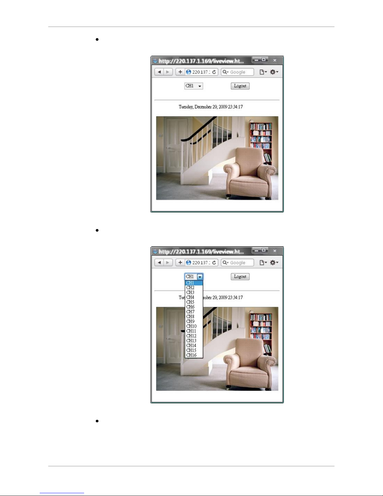
DVR User’s Manual
63
When the DVR is successfully connected, the live video of channel 1 will
be displayed, as shown below.
Click on the pull-down menu and change to any other desired channel to
view the corresponding live video.
Always remember to logout to make sure that next person can
successfully login.
Page 65

DVR User’s Manual
64
Appendix A: Recommended HDDs
Refer to the following list for some recommended HDDs to be used in the DVR.
Brand
Model Name
Model Number
Size
Seagate
Pipeline HD.2
ST3500312CS
500G
Barracuda ES.2
ST3500320NS
500G
Barracuda 7200.11
ST3500320AS
500G
Barracuda 7200.12
ST3500418AS
500G
Barracuda 7200.11
ST3750330AS
750G
Barracuda 7200.12
ST3750528AS
750G
Barracuda 7200.11
ST31000340AS
1000G
Barracuda 7200.12
ST31000528AS
1000G
Barracuda 7200.11
ST31500341AS
1500G
HITACHI
DeskStar
HDP725032GLA360
320G
DeskStar
HDP725050GLA360
500G
CinemaStar
HCP725050GLA380
500G
CinemaStar
HCS721010KLA330
1000G
Maxtor
DiamondMax 22
STM3500320AS
500G
Page 66
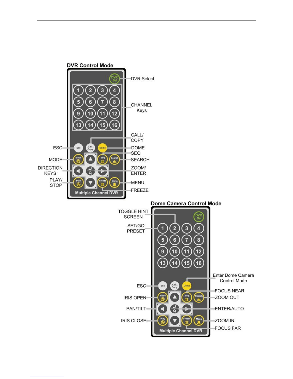
DVR User’s Manual
65
Appendix B: Remote Controller
The operational function keys on the remote control are listed as below figure:
Page 67

DVR User’s Manual
66
The keys of the remote control function as the keys of the front panel of the DVR. The only
difference between the remote control and the front panel keys is the “DVR SEL” key. The
DVR Selection key is used to switch control between each DVR.
The remote control can be used to control up to 16 DVRs. To setup the remote control, the
first thing is to assign a unique DVR Unit ID to each DVR.
Use the front panel of the DVR, and follow this path to change the DVR Unit ID, <Main
Menu> <System Setup> <RS485 Setup> <Unit ID>. Change the DVR Unit ID to
any number between 224 and 239, and exit the menu.
The ID Table is listed below for reference.
DVR Unit ID
224
225
226
227
228
229
230
231
Remote Control #
1 2 3 4 5 6 7 8
DVR Unit ID
232
233
234
235
236
237
238
239
Remote Control #
9
10
11
12
13
14
15
16
After the DVR Unit ID is changed, setup the “DVR SEL” of the remote control. Press “DVR
SEL”, and then press the Remote Control # immediately to select the DVR. For example,
assuming the DVR Unit ID is set to 225, press “DVR SEL” and then press “2” immediately.
Now, the remote control will only be able to control the specified DVR. Press “DVR SEL”,
and then press the Remote control # to switch between DVRs.
To exit the single DVR Control mode, press “DVR SEL”, and then press “ESC” to do so.
Page 68
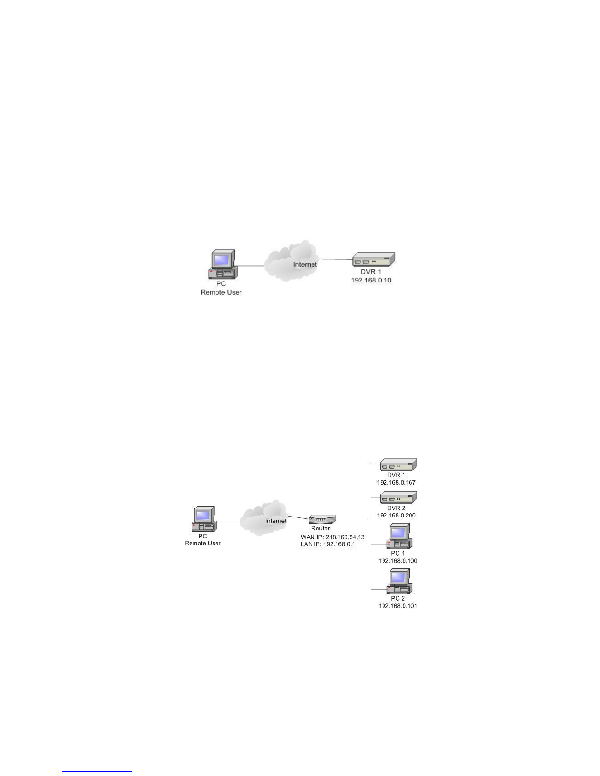
DVR User’s Manual
67
Appendix C: Setting up a DVR behind a Router
This appendix describes how to set up a router if the DVR connects to the internet via a
router.
To properly operate a web server, e.g. a DVR, users have to set up both the IP and port of
the DVR, which are essential for data and command transmission. The port setting is
adjustable in OSD setup menu of the DVR and only one port is needed to do remote
operation. Typically and by the default, the DVR operates on port 80, which is well known
as the http port. Please make sure that port 80 is not blocked by the ISP. Otherwise, a
different available port shall be reset and the setting of the DVR shall be changed.
In case a router or sometimes a DSL modem is in place, the real IP is now assigned to the
router instead of the DVR. The DVR is located behind the wall (router) and operates on
virtual IP. In most cases, virtual IP starts with 192.168.x.x. The router has two IP: one is real
IP (WAN IP); the other is virtual IP (LAN IP). The virtual IP would be 192.168.x.1. When the
remote users want to operate the DVR, they will have to send command to the real IP, i.e.
the router. Then the router has to map (forward) the command to the DVR. Thus, it is
required to set up the router for port mapping (forwarding) before images from the DVR can
be remotely viewed on a PC.
See the router manufacturer's websites for more instructions on port mapping.
Page 69
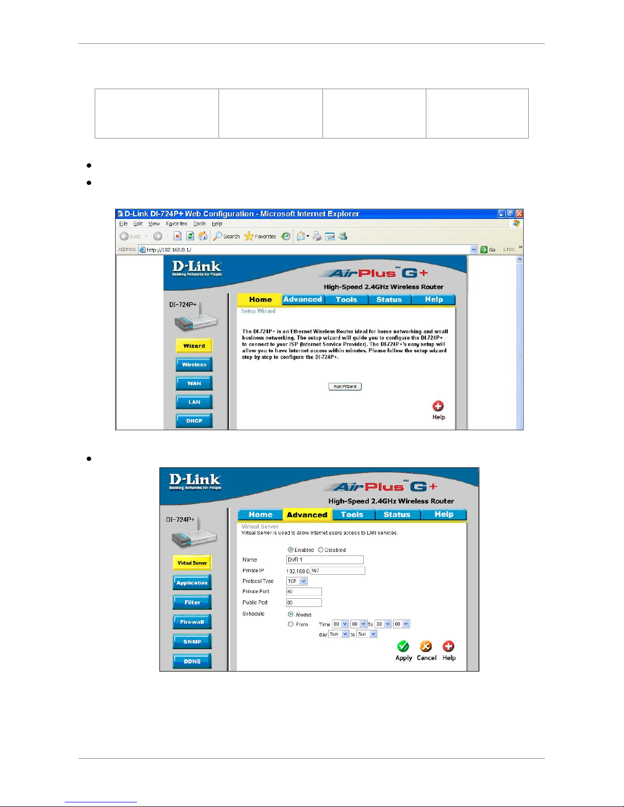
DVR User’s Manual
68
Following is an example of how the router should be set.
Router
(D-Link DI-724P+)
WAN IP: 218.160.54.13
LAN IP: 192.168.0.1
PC
IP: 192.168.0.100
DVR 1
IP: 192.168.0.167
Trigger port: 80
DVR 2
IP: 192.168.0.200
Trigger port: 81
To change the setting of the router, a PC with web browser is required.
Connect to D-Link DI-724P+ from PC via IE. The setup screen will be shown after
entering the correct username and password.
Click the <Advanced> tab and follow the steps to set up web port forward to DVR 1.
Page 70
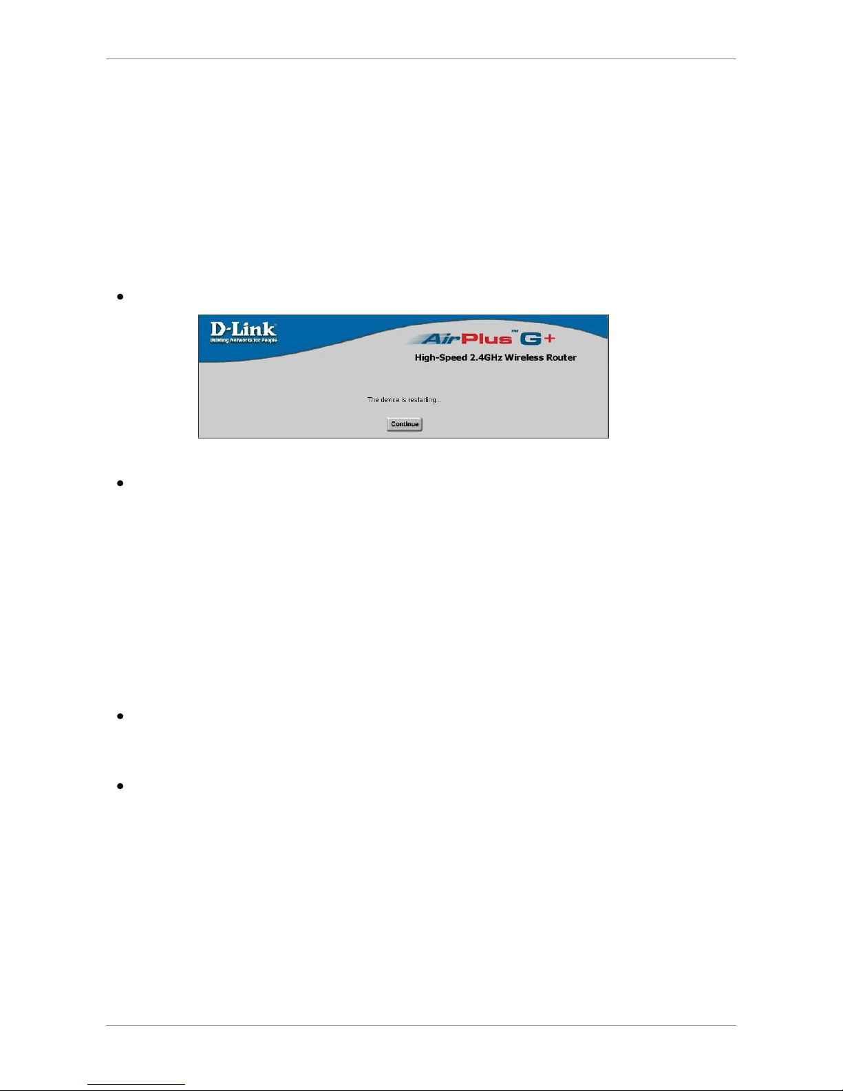
DVR User’s Manual
69
A. Select <Enabled> to set up the service.
B. Enter the name of the setting in the Name field: DVR 1.
C. Enter Private IP: 167
D. Choose <TCP> as the Protocol Type.
E. Enter Private Port: 80.
F. Enter Public Port: 80.
G. Click <Always> for the Schedule setting.
H. Click <Apply>.
Click <Continue> to go on when the following screen displays.
Follow the steps to set up web port forward to DVR 2.
A. Click <Enabled> to set up the service.
B. Enter the name of the setting in the Name field: DVR 2.
C. Enter Private IP: 200
D. Choose <TCP> as the Protocol Type.
E. Enter Private Port: 81.
F. Enter Public Port: 81.
G. Click <Always> for the Schedule setting.
H. Click <Apply>.
Now DVR 1 can be connected via http://218.160.54.13:80 and DVR 2 can be connected
via http://218.160.54.13:81.
If there are more than one DVR behind the router, repeat the steps for port mapping
setting.
 Loading...