

Page 1
Low or No Volume
• Check that the video cable connecting the
camera to the monitor is connected properly
Manual
DP-121Q
Video Door Phone
ENFORCER VIDEO DOOR PHONE
12
FCC COMPLIANCE STATEMENT
Information to the user: This device is in conformance with Part 15 of the FCC Rules and Regulations for Information
Technology Equipment. Operation of this product is subject to the following two conditions: (1) this device may not cause
harmful interference, and (2) this device must accept any interference received, including interference that may cause
undesired operation.
IMPORTANT
Users and installers of this product are responsible for ensuring this product complies with all national, state, and local
laws and statutes related to monitoring and recording audio and video signals. SECO-LARM will not be held
responsible for the use of this product in violation of any current laws or statutes.
The screen displays no image
• Check that the camera is powered up
• Check that the monitor is powered up
• Check that the power supply’s polarity is correct
• Check that the video cable connecting the
camera to the monitor is connected properly
WARRANTY This SECO-LARM product is warranted against defects in material and workmanship while used in normal
service for a period of one (1) year from the date of sale to the original consumer customer. SECO-LARM’s obligation is
limited to the repair or replacement of any defective part if the unit is returned, transportation prepaid, to SECO-LARM.
This Warranty is void if damage is caused by or attributed to acts of God, physical or electrical misuse or abuse, neglect,
repair, or alteration, improper or abnormal usage, or faulty installation, or if for any other reason SECO-LARM determines
that such equipment is not operating properly as a result of causes other than defects in material and workmanship.
The sole obligation of SECO-LARM, and the purchaser’s exclusive remedy, shall be limited to replacement or repair only,
at SECO-LARM’s option. In no event shall SECO-LARM be liable for any special, collateral, incidental, or consequential
personal or property damages of any kind to the purchaser or anyone else.
NOTICE: The information and specifications printed in this manual are current at the time of publication. However, the
SECO-LARM policy is one of continual development and improvement. For this reason, SECO-LARM reserves the right
to change specifications without notice. SECO-LARM is also not responsible for misprints or typographical errors.
Copyright © 2010 SECO-LARM U.S.A., Inc. All rights reserved. This material may not be reproduced or copied, in
whole or in part, without the written permission of SECO-LARM.
16842 Millikan Avenue, Irvine, CA 92606
Website: www.seco-larm.com
Tel: 800-662-0800 / 949-261-2999 Fax: 949-261-7326
Email: sales @seco-larm.com
Troubleshooting:
file: mi-DP-121Q_VDP(6j).cdr
WARNING
Stop using the camera if there is a malfunction like smoke or unusual heat, as that could cause a fire or electric shock. Do
not open the case of this device, as there are no field-serviceable parts inside.
The screen image is dim
• Clean the lens using a soft, clean cloth
• Adjust the brightness on the phone
The image has poor contrast
• Adjust the contrast on the phone
The image is displayed incorrectly
• Adjust the angle and/or location of camera
The phone does not ring when
• Adjust the ringer volume on the phone
request-to-enter button is pressed
PICCN2
Made in China
SECO-LARM U.S.A., Inc.
ENFORCER
Connection
E1
E2
E3
E4
Wire Color
Wire Connection Chart
Note: Please use this Wire Connection Chart when installing the camera to record the wire
colors for each connection. Make sure wire connections between monitors and
cameras are all connected correctly before powering the unit.
Page 2
E1
E2
E3
E4
Note: Make sure wire connections between monitors and cameras are all connected correctly before
powering the unit. Use the Wire Connection Chart on the front cover to record the wires used.
ENFORCER VIDEO DOOR PHONE
11
Note: Professional installation recommended
Wiring Diagram –
Connecting to a Second Monitor:
Addition al
Optional
Monitor
SECO-LARM U.S.A., Inc.
Type
Chip
Resolution
Relay output
Lens
Min. illumination
Weight
Dimensions
Display
Weight
Power consumption
Power source
Dimensions
B/W Camera
CCD
380 TV lines
1 Amp@12VDC max. dry contact
3.6mm
0.8 Lux
8 oz. (220g)
1
5 / " x 3 " x 1 "
4
(134 x 100 x 38 mm)
15 1
/ /
16 2
CRT
2 lb. 8 oz. (1.1kg)
800mA@15~18 VDC
15VDC +/- 15%
5 11 1
9 / " x 7 / " x 3 / "
8 16 8
(245 x 196 x 79 mm)
ENFORCER VIDEO DOOR PHONE
2
SECO-LARM U.S.A., Inc.
Camera has 6 LEDs for nighttime
operation.
Remotely and securely talk to visitors and
unlock doors, gates, etc. from the monitor.
Easily connect an additional monitor
and/or an additional camera.
Built-in microphone: Talk and listen to
visitors at the same time.
Camera contains built-in angle
adjustment.
Specifications:
Table of Contents
Camera
Features:
Additional Ordering Information:
Monitor
Video Door Phone Kit
DP-121Q Contains:
Features
Specifications
Parts List
Overview
Installation Notes
Installation (monitor)
Installation (camera)
Operating Instructions
LED Indicator
Dimensions
Sample Application
Additional Accessories
Wiring Diagram
Troubleshooting
Simple 4-wire connection.
Easy surface-mount installation.
Camera and monitor turn on and off with
the push of a button.
Camera and monitor turn off automatically
when not in use.
Adjustable contrast, brightness, and ringer
volume.
LED indicators for power and operation.
Camera
Camera bracket
Screws
Screw anchors
Crimp-on terminals
Camera screw
Monitor
Monitor Bracket
AC Power Adapter
Molex wiring harness
x 1
x 1
x 8
x 8
x 6
x 1
x 1
x 1
x 1
x 2
Additional Monitor*
Monitor Bracket
AC Power Adapter
Molex wiring harness
Screws
Screw anchors
x 1
x 1
x 1
x 1
x 4
x 4
Additional Monitor
DP-121SQ Contains:
2
2
2
3
4
4
6
7
8
8
9
9
10
12
.............................................
.....................................
............................................
............................................
................................
...........................
...........................
........................
.....................................
........................................
............................
.......................
..................................
..................................
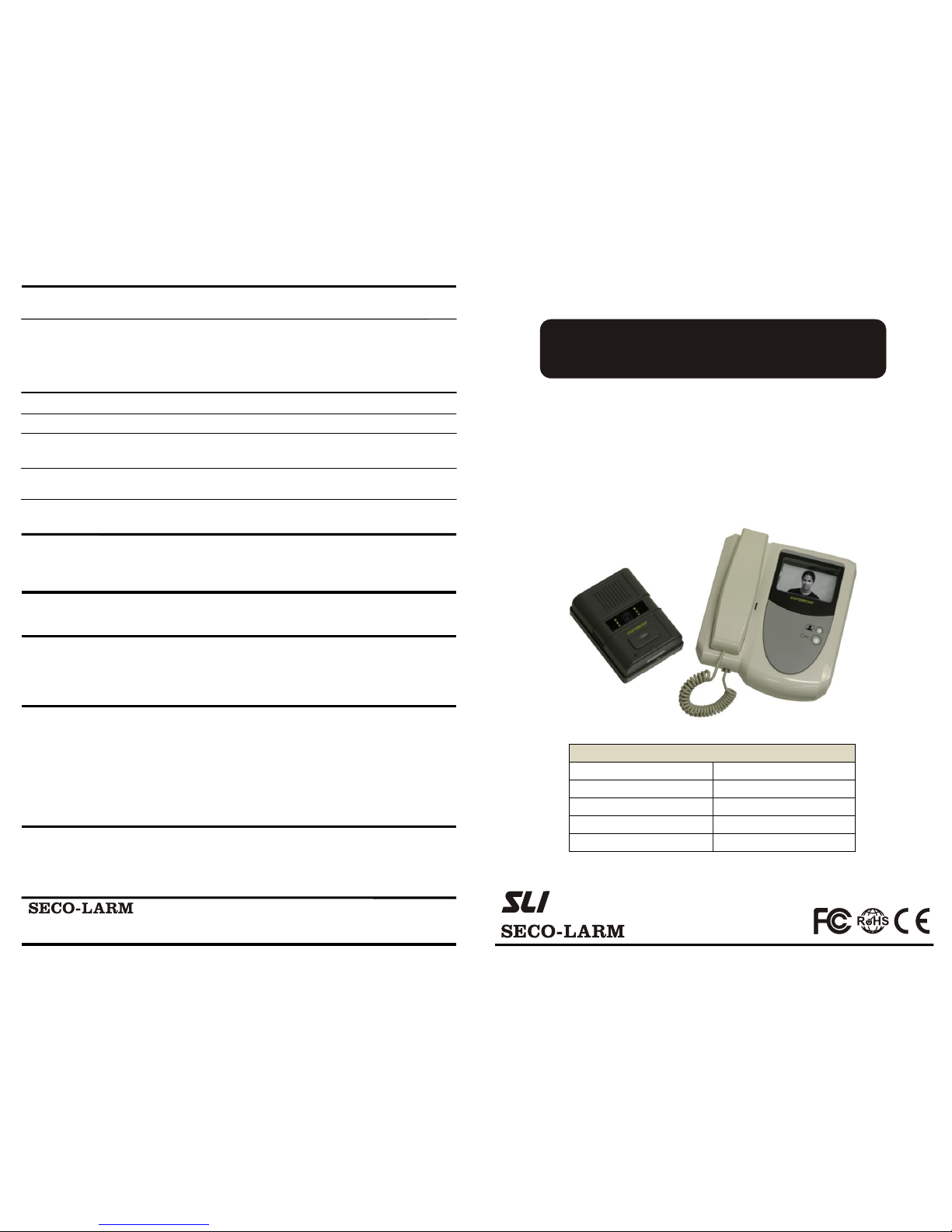
The ENFORCER DP-121Q Video Door Phone is the easy, secure way to identify visitors.
Suitable for home or business use, the ENFORCER DP-121Q Video Door Phone can be
installed at doors or entrances. A crisp image of the visitor is shown in real-time on the
phone's monitor, while the camera's built-in LEDs provide a clear image even in low-light
conditions. A built-in microphone and speaker on the camera unit lets users communicate
with visitors. Authorized visitors can then be granted entry with a push of a single button.
E1
E2
E3
E4
Additional monitor cannot
be used in place of the
original/main monitor.
*
Parts List:
Page 3
E4
E3
E2
E1
E1
E2
E3
E4
E1
E2
E3
E4
ENFORCER VIDEO DOOR PHONE
3
ENFORCER
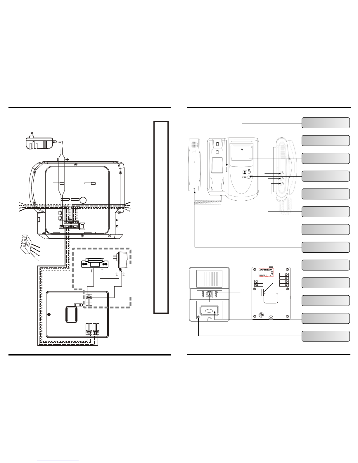
Speaker
Overview:
Monitor
Camera
ENFORCER
®
Display – Clearly shows an
image of the visitor
LED Indicators – Shows
power and handset status
Camera Button – Camera
on/off, switches cameras
Door Unlock – Grant access
to visitors
Ringer Volume – Sets the
volume of the ringer
Brightness – Sets the
brightness on the display
Contrast – Sets the contrast
on the display
Handset – Talk and listen
to visitors
High-intensity LEDs – For
nighttime operation
Camera Angle Adjustment –
Built-in for easy installation
Lens – 3.6mm for a wideviewing angle
Request-to-Enter – Monitor
rings when button is pressed
Microphone – Talk and listen
to visitors remotely
SECO-LARM U.S.A., Inc.
E1
E2
K1
E3
K2
E4
Model: DP-121CQ
Video Door Phone
05A08
PICCN2
Camera
ENFORCER VIDEO DOOR PHONE
10
Wiring Diagram – Connecting to an Electric Doorstike:
Add ition al Opti onal Mo nitor
Max . Camer a Dista nce: 16 5ft (50 m)
Mon itor
Cam era
AC Adapter
(not included)
Door Strike
(not included)
Sample Application
To cam er a 2
SECO-LARM U.S.A., Inc.
NOTE: Please use the Wire Connection Chart included on the front cover of this manual to write in the color of the wires being
used. Make sure wire connections between monitors and cameras are all connected correctly before powering the unit.
E2
E3
E4
E
1
Page 4
ENFORCER VIDEO DOOR PHONE
4
1. Unpack the video door phone and note the included parts.
2. Read this manual thoroughly. A clear understanding of the manual will make
installation and operation much easier.
3. Find a good location to mount the monitor and camera. Make sure there is enough
room to wire both units correctly with 22AWG 4-conductor wire.
4. Use only untwisted-pair wire; twisted-pair wire may cause interference.
5. Avoid mounting either the cameras or the monitors near sources of strong
electromagnetic signals or other electronic devices as they may cause interference.
6. Avoid mounting the cameras in direct sunlight or exposing the camera to strong
vibrations or direct rain or other moisture, as it may damage them.
7. The camera and the monitor contain no user-serviceable parts. Opening them may
damage sensitive components and void the warranty.
1. The monitor must be positioned so that the image
can be seen clearly and the user can operate the
monitor’s functions.
2. Use the mounting bracket as a template to pencil
in where to drill the holes for the mounting bracket
screws.
3. Drill the mounting bracket holes as needed. Drill a
hole large enough to fit the 22AWG 4-conductor
wire which will run through the wall from the
camera to the monitor (see Figure 1).
4. Using the 4 included screws and 4 screw anchors,
attach the monitor bracket to the wall, running the
cable through the large hole in the mounting
bracket.
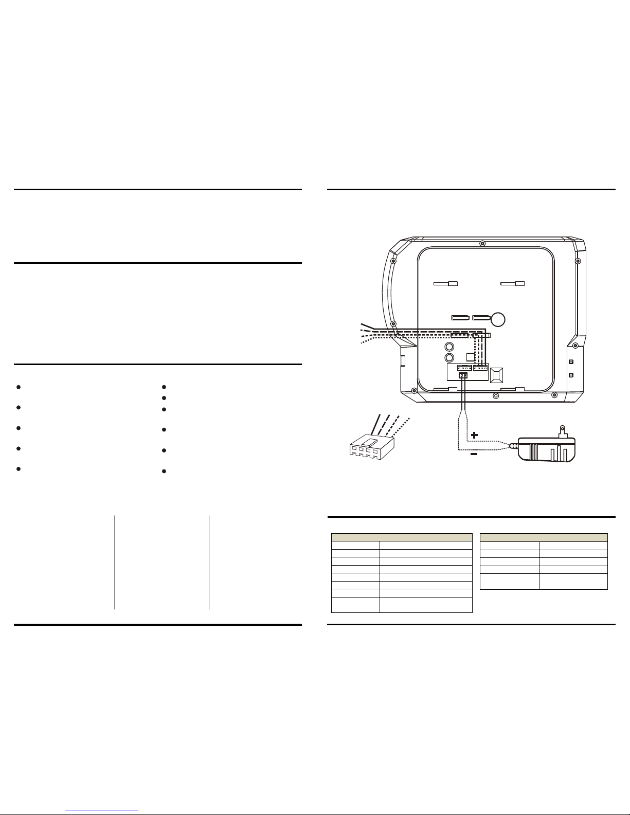
5. Plug the brown 4-pin plastic connector from the
camera into the “Camera 1” socket (see Figure 2).
NOTE: If using only one monitor and camera,
there will be unused sockets on the back of the
monitor.
Installing the Primary Monitor:
Drill a hole in this shaded area large
enough to run 22AWG 4-conductor
wire to the camera and an additional
monitor.
Figure 1 – Monitor
Mounting Bracket
Mounting bracket holes
Installation Notes:
SECO-LARM U.S.A., Inc.
ENFORCER VIDEO DOOR PHONE
9
Sample Application:
Additional Accessories Available from SECO-LARM:
Door Strikes
(not included)
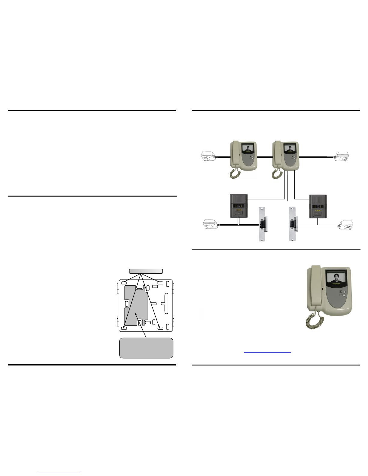
Connect 2 monitors to 1 camera.
Remotely unlock 2 protected entrances.
Extra monitor is easily installed with a
single connection.
DP-121SQ - Additional Monitor
SECO-LARM carries a complete line of security products.
Please visit www.seco-larm.com for more information.
Screen images simulated
Up to 2 monitors can be connected to 1 camera.
The DP-121Q Video Door Phone can be
expanded to connect an additional monitor.
AC/DC Power
Adapter
(not included)
AC/DC Power
Adapter
(not included)
Camera 1
Camera 2
AC/DC Power
Adapter
(included)
AC/DC Power
Adapter
(included)
Monitor 1
Monitor 2
(optional)
(optional)
SECO-LARM U.S.A., Inc.
Note: A Wire Connection Chart has been included on the front cover of this manual.
Please use it to write in the color of the wires being used. This can be used as a
reference when installing the camera. Make sure wire connections between
monitors and cameras are all connected correctly before powering the unit.
Page 5
ENFORCER VIDEO DOOR PHONE
5
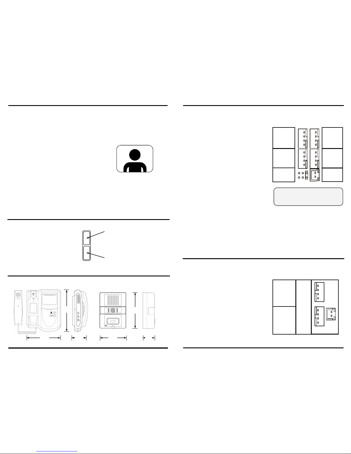
Camera 2 and Monitor 2 sockets Camera 2 and Monitor 2 sockets
are used only with optional are used only with optional
additional monitor and camera.additional monitor and camera.
Jumpers x 3
Not Used
6. Plug the AC Power Adapter’s cable into the
“Power” socket on the back of the monitor.
7. Run the wires going to the camera under
the plastic hooks on the back of the monitor
so that any tension on them will not be
directly transferred to the plugs or sockets.
8. Plug the AC power adapter into a 120VAC
socket.
9. Test the monitor and camera unit by
pressing the camera button. The image in
front of the camera should be displayed
clearly.
Note: Please use the Wire Connection Chart
included on the front cover of this
manual to write in the color of the wires
being used. This can be used as a
reference when installing the camera.
Make sure wire connections between
monitors and cameras are all connected
correctly before powering the unit.
10.If using a secondary monitor, follow steps
1-4 on page 4.
11.Plug the brown 4-pin plastic connector
from the camera into the “Main Monitor”
socket (see Figure 3).
NOTE: There will be an unused socket
on the back of the secondary monitor.
12.Follow steps 6-9 above to complete the
installation
Figure 2 – Back of Primary
Monitor Detail
Monitor
2
Camera
2
Not
Used
Camera
1
Camera 2 and Monitor 2 sockets are
used only with optional additional
monitor or camera (discontinued).
Figure 3 – Back of
Secondary Monitor Detail
Main
Monitor
Not
Used
Power
SECO-LARM U.S.A., Inc.
Power
ENFORCER VIDEO DOOR PHONE
8
Operating Instructions (cont):
Monitoring the entrance:
1. To see and hear what is going on at the
entrance, lift the handset and press the
Camera Button. The camera and monitor will
automatically switch on.
2. If an additional camera is installed, pressing
the Camera Button a second time will
switch the image displayed on the monitor to
the view from the other camera. Pressing the
camera button again will turn off the cameras.
3. When finished, simply hang up the handset
and the camera will switch off. If the handset is
not hung up, the camera will automatically
switch off after 2 minutes.
LED Indicator:
Installing a Second Monitor:
A status LED indicator is located on
the front of the monitor. The LED
displays power information as well as
the status of the handset.
LED Indicator
Green LED – Solid green LED
indicates standby mode. Flashing
green LED indicates camera “on”.
(2 monitors only)
Red LED – Solid red LED indicates
standby mode. Flashing red LED
indicates camera “on”.
Dimensions:
ENFORCER
711/
16
(196mm)
315/
16
(100mm)
51/
4
(134mm)
11/
2
(38mm)
95/
8
(245mm)
31/
8
(79mm)
®
ENFORCER
Camera Button
SECO-LARM U.S.A., Inc.
Note: Make sure wire connections between monitors and cameras are all connected correctly.
E4
E3
E2
E1
E4
E3
E2
E1
E1
E2
E3
E4
E1
E2
E3
E4
E4
E3
E2
E1
E4
E3
E2
E1
-----
-----
-----
-----
-----
-----
-----
-----
-----
-----
-----
-----
E4
E3
E2
E1
E4
E3
E2
E1
Page 6
ENFORCER VIDEO DOOR PHONE
6
Installation (camera):
Direct
Sunlight
Rain
Snow
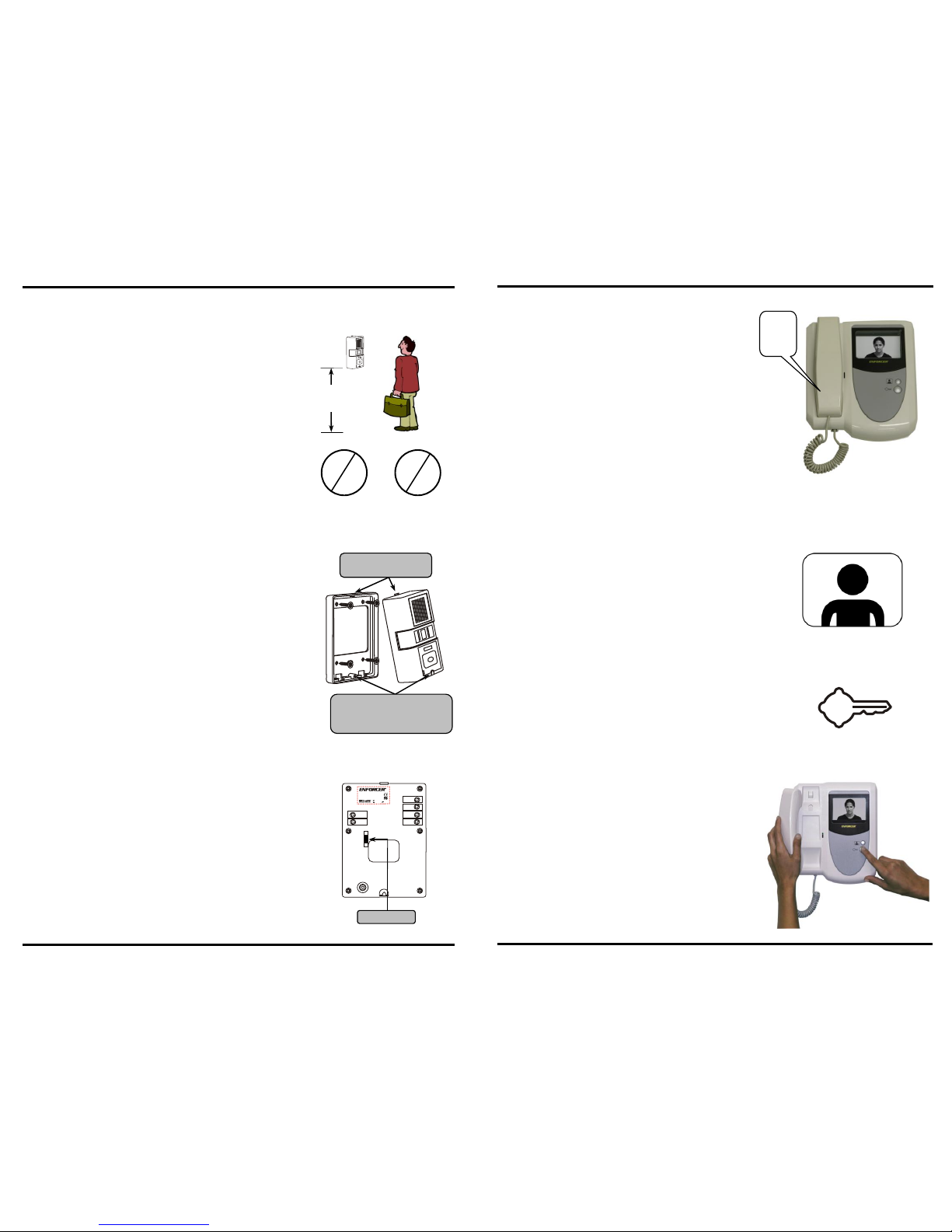
Figure 6 – Rear of
Camera Unit
Tilt Adjustment
Figure 5 – Camera and
Mounting Bracket
The tab on top of the
camera slides in first.
Secure the camera to the bracket
with the hidden camera screw
underneath this slide-out cover.
5’
(150 cm)
1. Position the camera so the area to be monitored is
easily visible, typically 5 feet (150cm) above the
ground (see Figure 3). Do not position the camera in
direct sunlight or where it will be exposed directly to
rain or snow.
2. Cut a hole large enough to run the 22AWG 4conductor wire through the wall to where the camera
unit is to be mounted. If using a locking device, the
wires used to control the device must also be run
through this hole.
3. Run the 22AWG 4-conductor wire from the camera
location to where the monitor is mounted. The
maximum wiring distance is 165’ (50m) (see Wiring
Diagram, page 8).
4. Using the 4 included screws and 4 screw anchors,
attach the camera mounting bracket to the wall (see
Figure 4).
5. Connect the wires coming from the monitor to the
proper terminals E1 thorough E4 on the back of the
camera (see Figure 5).
6. If the Door Phone will control a locking device,
connect the wires coming from the locking device to
the relay output terminals K1 and K2 on the back of
the camera (see the Sample Application on page 11).
7. Set the desired camera angle up and down by
moving the tilt adjustment in the opposite direction.
8. Push the tab on top of the camera into the top of the
bracket. Make sure that no wires are preventing the
camera from seating properly in the bracket. Pull the
slide-out cover to expose the hidden screw location.
9. Secure the camera to the mounting bracket with the
included camera screw. Close the cover at the bottom
of the camera to conceal the camera screw.
Figure 4 – Camera
Mounting Location
SECO-LARM U.S.A., Inc.
E1
E2
K1
E3
K2
E4
Model: DP-121CQ
Video Door Phone
05A08
PICCN2
Camera
ENFORCER VIDEO DOOR PHONE
7
Operating Instructions:
1. When the request-to-enter button on the camera
is pressed, the monitor will ring twice. After
ringing, any connected monitors will switch on.
2. When the handset is picked up, audio can be
heard through the handset.
NOTE: If two monitors are connected, the monitor
that does not answer the call will turn off.
3. If an additional camera is installed, pressing
the Camera Button will switch the image
displayed on the monitor to the view from the
other camera. Pressing the camera button again
will turn off the cameras.
4. The monitor is automatically switched off after the
handset is hung up, 1 minute of inactivity pass, or
the Camera Button is pressed.
See the Wiring Diagram on Page 8 for more details.
To allow access to the entrance, press the Unlock
Button. This signals the door strike or lock to allow
entry.
IMPORTANT: The door strike or lock will only
remain unlocked while the Unlock
Button is pressed.
For Example:
If the entrance door is located a few steps from
the camera, the Unlock Button must be pressed
long enough to give the visitor enough time to
open the entrance.
Ring
Ring!
Camera Button
Unlock Button
If connected to a door strike or
other locking device:
SECO-LARM U.S.A., Inc.
 Loading...