

Enfasco RH160E Instructions, Detailed Maintenance & Parts List
1
RH160E
Enfasco Spin/Pull/Spin
Rivet Nut setting Tool (Spin /Pull)
Instructions, Detailed Maintenance & Parts List
2
Air Feed
Use only compressed air. Check airline for damage from humidity & contaminants.
In order to protect the tool from premature wear it is recommended a filter separator &
regulator assembly be used. A lubricator is not necessary but a water separator is
highly recommended.
Normal working pressure is 85-95 PSI. Air connection thread size ¼”- NPT.
WARNING: Do not use air supply greater than recommended or tool
may be damaged or burst. Do not use oxygen, combustible gases or
bottled gases as a source for this tool. Gases could cause the tool to
explode.
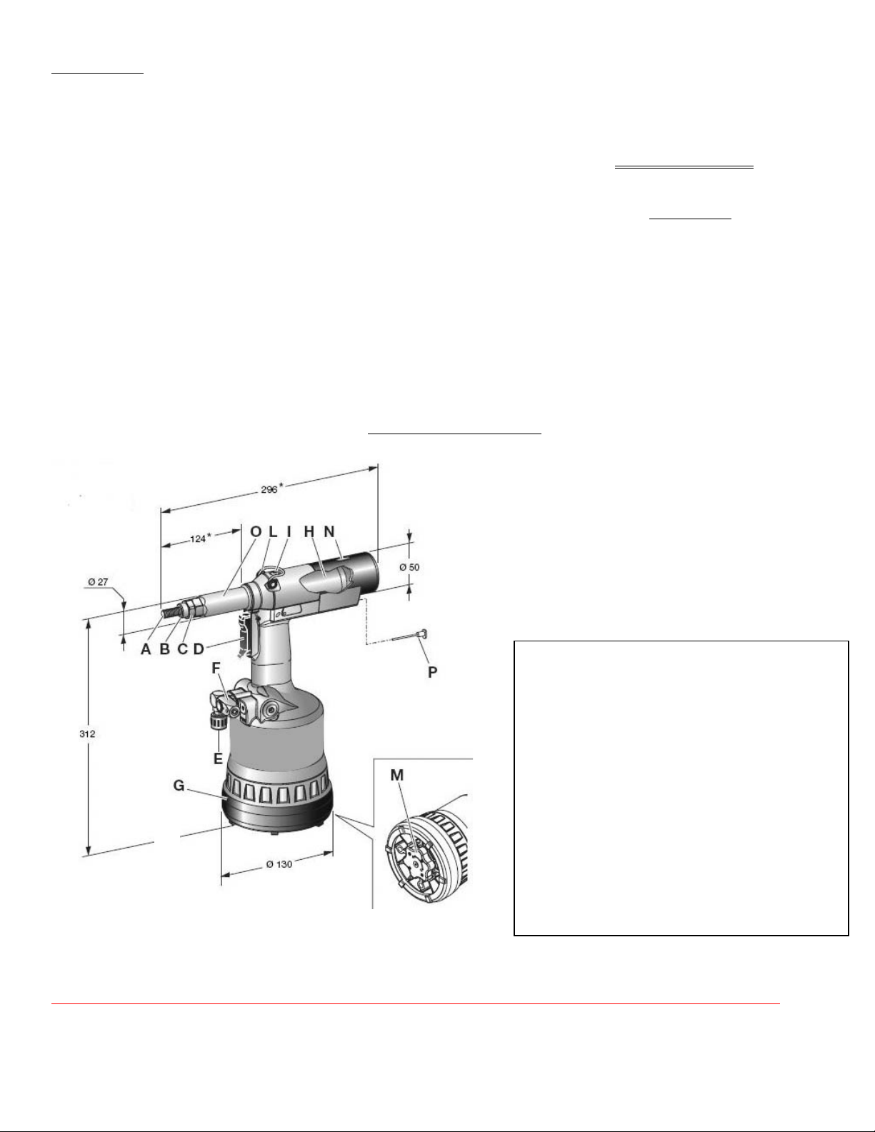
Main Components
Always Disconnect Air supply before working on internals of tool
A: Mandrel
B: Nosepiece
C: Nosepiece Lock Nut
D: Trigger
E: Air Connection (1/4-20 NPT female)
F: Pressure control Valve
G: Protective Bottom
H: Pneumatic Motor
I: Fluid Plug
L: Balancer Connection
M: Stroke Adjusting Knob
N: Stroke Indicator
O: Head
P: Forced Unscrewing Rod
J
3
MAINTENANCE
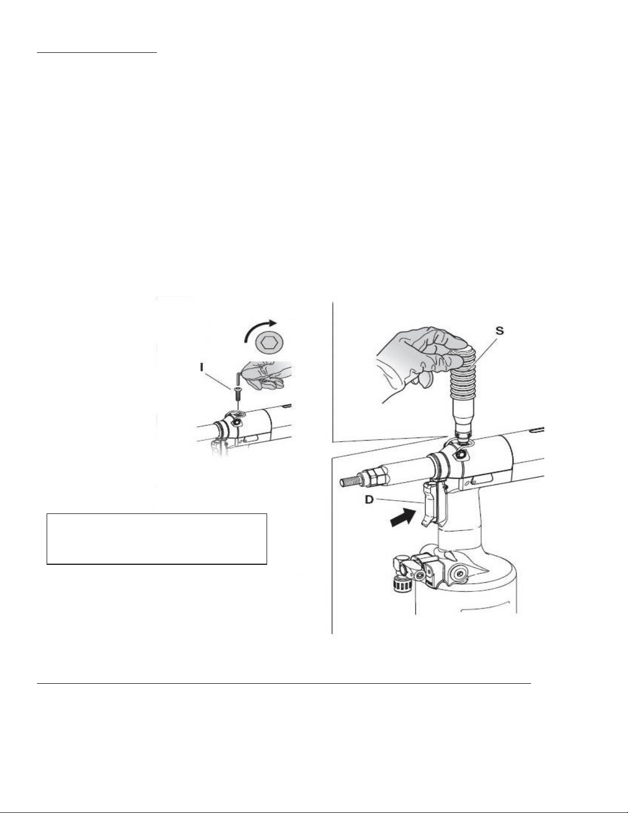
ADDITION OF HYDRAULIC FLUID (Use Mobil DTE 24)
To purge all the oil from the tool, Hook tool to air supply and remove oil fill plug (I) and lay flat
on a work bench. Place tool in a bag and cycle tool 5 or 6 times which will purge all the
remaining oil from the tool. Screw oil container and cycle tool until oil fills the tool and no air
bubbles remain.
Note: If tool stroke seems to not be adequate, add oil
The Hydraulic oil should be topped off after a long period of usage or when there is a power loss
of the tool. Put the tool in a vertical position rotating the knob (M) towards the plus sign + up to
the end of the stroke, and remove plug (I) by using a 4mm Allen wrench (supplied). After
removal of plug (I), check the oil level in order to avoid overflowing. Next screw the oil
container (S) supplied into the oil inlet hole until it is seated. While keeping the tool in the
vertical position connect the air line and push button (D) and then cycle the tool several times
until air bubbles in the oil container (S) stop appearing in the oil container (S). This indicates that
tool is filled of oil and is ready for use. Disconnect the air line and unscrew the oil container (S)
from tool and replace plug (I) first checking to be sure the washer on plug is in position and not
damaged.
IMPORTANT: Make sure plug (I) is
tightened at a torque corresponding to
min. of 3.6 ft-lb and a max. of 5.9 ft-lb
4
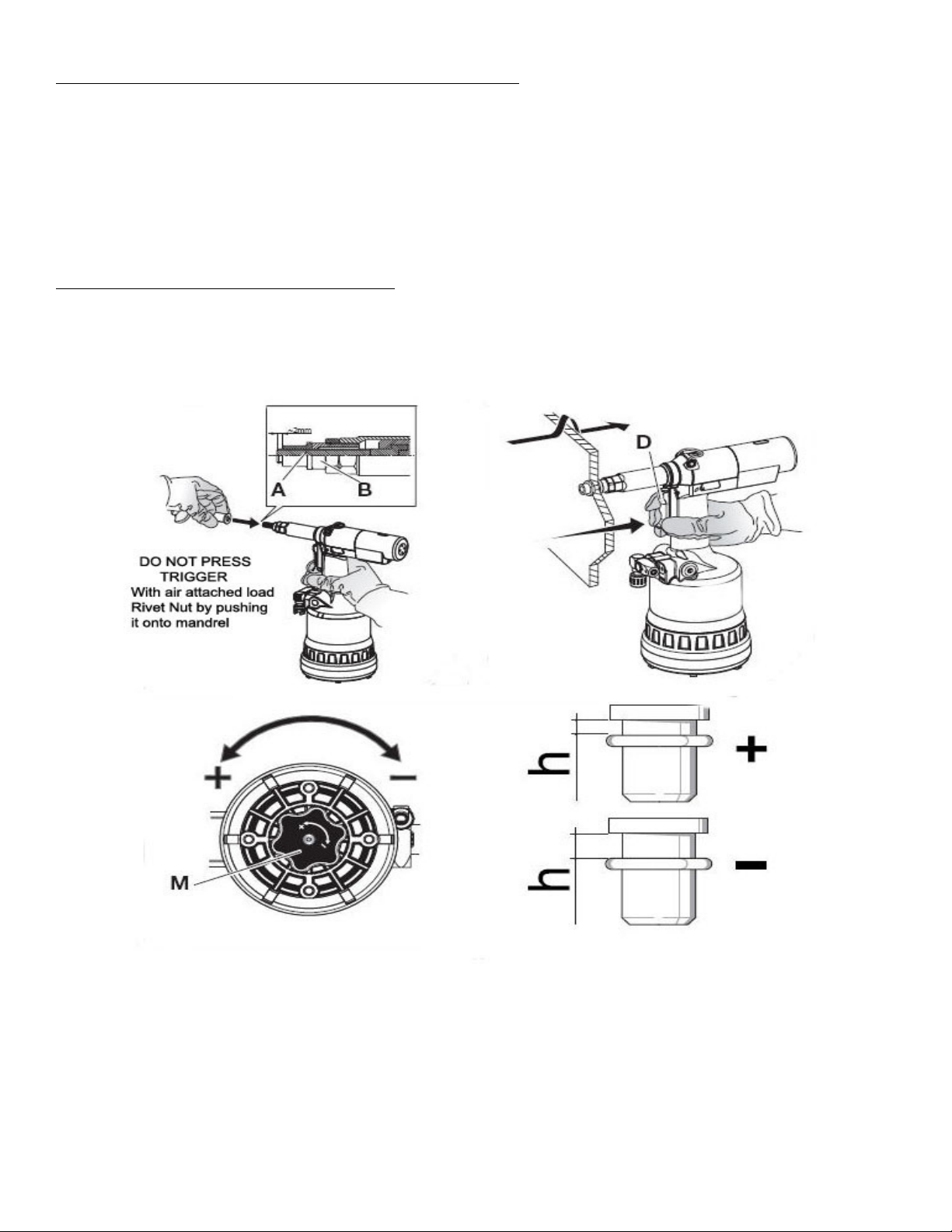
Changing Mandrel and Nosepiece
Follow Instructional DVD Video. First, Loosen Anvil Jam nut and unthread anvil Mandrel housing. Next,
unthread mandrel housing exposing the mandrel. Pull Mandrel toward you, removing from slot. Make sure hex
driver is secure in mandrel and insert in slotted mandrel holder
Adjusting Stroke Length (See Enfasco Pull-up Factor Chart)
Before using the tool and after each change of thread size, the stroke should be adjusted according to the
dimensions, type of insert and thickness of material rivet nut is to be installed in. Before setting rotation of knob
(M) in the direction indicated either decreases (-) or increases (+) the clamping force (h).
 Loading...