

EnerWorks EWRA2, EWRA1 Installation Manual

Module 4
Solar Collector
Installation Manual
1, 2, 3 & 4 Collector Pre-Heat Appliances
(EWRA1, EWRA2)
Rev. 2013,04,23
1 & 2 Collector Single Tank Appliances (USA only)
( )EWRA1-ST, EWRA2-ST
Solar Water Heating Appliances
EnerWorks Inc.
969 Juliana Drive
Woodstock, ON
N4V 1C1, Canada
Tel: (519) 268-6500
Toll-free: 1-877-268-6502
Fax: (519) 268-6292
www.enerworks.com
© 2013 enerworks
Solar Collector
Installation Manual
Foreword
EnerWorks encourages installers of EnerWorks products to always keep workmanship, best practices
and safety in mind. An organized installation will benefit both installer and end-user.
The EnerWorks Solar Collector is one of the highest-rated in North America. This assessment was
carried out by third-party testing under the supervision and scrutiny of the Solar Rating & Certification
Corporation™ (SRCC™). The EnerWorks Heat Safe Solar Collector has SRCC™ OG-100 certification
(Certification #: 100-2005-014A) and the EnerWorks Residential Solar Water Heating Appliances are
certified to OG-300 standards. This certification does not imply endorsement or warranty of these
products by the SRCC™.
The Pre-Heat and Single Tank Appliances described in this manual, when properly installed and
maintained, meet or exceed the standards established by the Florida Solar Energy Center (FSEC), in
accordance with Section 377.705, Florida Statutes. This certification does not imply endorsement or
warranty of this product by the Florida Solar Energy Center or the State of Florida.
The EnerWorks Pre-Heat Appliance is the first system in North America to achieve the Canadian
Standards Association (CSA) certification (CSA F379.1). This certification does not imply endorsement
or warranty by CSA.
Appliance must only be installed by an EnerWorks-authorized
dealer or warranty is void.
Recognize this symbol as an indication of important safety information!
EnerWorks Residential Solar Water Heating Appliances must be installed as
directed by this manual by an EnerWorks-authorized dealer or warranty is void.
CALIFORNIA PROPOSITION 65 WARNING: This product contains
chemicals known to the State of California to cause cancer,
birth defects or other reproductive harm.

Solar Collector
Installation Manual
CARE, HANDLING & STORAGE
EnerWorks Solar Collectors are manufactured with tempered glass. Though extremely resistant to
impact, tempered glass can break if an edge is subjected to stress. During storage and installation,
protect glass edges. Glass breakage is not covered by warranty.
Store collectors in a dry place, lying flat with glass up, or leaning on long edge with glass facing out and
connections at top. Protect collector from scratches and damage by placing it on a soft surface such as a
blanket or cardboard. When hoisting collectors to roof, be very careful not to bang glass edge.
Collectors must not be levered over ladder or eave as they may be damaged. Be very careful of collector
connections as they are soft copper and may be easily damaged. A leak-proof heat-transfer fluid loop
can only be achieved if collector connections are not damaged.
Do not store collectors outside with glass face down. Due to EnerWorks’ patented stagnation-control
device, back of collector is not sealed to atmosphere. Rain may enter collector if it is stored face down.
Any damage due to ingress of water is not covered by warranty.
It is best to store both the EnerWorks Solar Collectors and the EnerWorks Energy Station in a cool, dry
place.
Module 4
1

Contents
Solar Collector
Installation Manual
1 – Safety
.................................................................................................................................... 3
2 – EnerWorks Solar Water Heating Appliance
2.1 Description
..................................................................................................................4
2.2 Pre-heat Appliance Schematic
2.3 Single Tank Appliance Schematic (USA only)
3 – Site Evaluation
.......................................................................................................................7
3.1 Collector Location, Orientation and Shading
3.2 Available Roof Space
3.3 Collector Racks
3.4 Line-Set
...................................................................................................................... 8
.................................................................................................... 8
............................................................................................................ 8
3.5 Location of Energy Station and Solar Storage Tank
4 – Line-Set Installation
4.1 Line-Set Description
4.2 Line-Set Routing
4.3 Line-Set Installation
5 – C-Channel Installation
............................................................................................................... 8
..................................................................................................... 8
........................................................................................................... 9
....................................................................................................10
......................................................................................................... 11
5.1 Locating Rafters and Positioning C-Channel
5.2 Securing C-channel Asphalt roof (Shingles)
5.3 Securing C-channel to S etal Roof
5.4 Roof-Penetration Flashing Boot
6 – Solar Collector Installation
6.1 Preparation of Collector(s)
tanding Seam M
................................................................................... 15
..................................................................................................... 16
.......................................................................................... 16
6.1.1 Converting Collector(s) from Left to Right
6.1.2 Installing Temperature Sensor (Thermistor)
6.1.3 Installing Collector Mounting Brackets
6.2 Hoisting and Securing Collectors to Roof
6.2.1 Ladder Hoist or Shingle-Lift
...................................................................................... 23
6.2.2 Scissor Lift or Articulating or Forklift Boom
6.2.3 Scaffolding
6.2.4 Ladder and Lift Line
6.3 Securing Collectors to C-Channel
6.4 Collector Configurations
6.4.1 One-Collector Configuration
6.4.2 Two-Collector Configuration
6.4.3 Three-Collector Configuration
6.4.4 Four-Collector Configuration
............................................................................................................. 23
.................................................................................................. 24
................................................................................ 25
................................................................................... 26
.................................................................................... 26
................................................................................... 27
................................................................................... 27
.................................................................................... 28
6.5 Line-Set and Control-Wire Connections
7 – Collector Flashing and Leaf-Guard Installation
7.1 Side-Flashing for 1-Collector Appliances
7.2 Center-Flashing for 2, 3 and 4-Collector Appliances
7.3 Leaf-Guard Installation
................................................................................................ 33
............................................................................... 4
........................................................................5
...............................................................6
................................................................... 7
........................................................... 8
................................................................. 11
................................................................. 13
........................................................ 15
................................................................... 17
............................................................... 20
...................................................................... 21
...................................................................... 22
................................................................... 23
......................................................................... 29
......................................................................... 30
..................................................................... 31
...................................................... 31
Product and Installation Registration Form
Residential Site Survey
Tool & Supply Checklist
2
................................................................................................................. 35
.................................................................................................................. 36
..................................................................................... 34
Module 4
Solar Collector
Installation Manual
1 – Safety
EnerWorks assumes no responsibility for damage, loss or injury related to installation of this
appliance.
Observe any and all regulations relating to installation of solar appliances and to plumbing to
potable water supply. Plumbing and/or building permits may be necessary. EnerWorks Solar
Water Heating Appliances utilize a single-wall as well as double-wall heat exchangers.
Selection must be acceptable in the jurisdictions.
Assemblies, installation and materials used during installation shall meet applicable
requirements of local, regional, state, provincial, and federal regulations and fire codes,
national roofing contractors association practices. Any penetrations made in drywall or any
other firewall must be fixed to maintain integrity of fire protection.
All persons working on roofs should have successfully completed a fall-safety course and
should be properly equipped with appropriate safety equipment.
Module 4
3

Solar Collector
Installation Manual
2 – EnerWorks Solar Water Heating Appliance
2.1 Description
The EnerWorks Solar Water Heating Appliance has four main parts – the solar collectors, the line-set,
the Energy Station and the solar storage tank.
The Energy Station uses a pump to circulate a heat-transfer fluid through the “collector loop”. This
collector loop includes the solar collectors, the fluid lines or “line-set” and a heat exchanger. The
collector loop is a “closed loop”, meaning there is no contact of the heat transfer fluid with your potable
water or with the atmosphere. The collector loop contains only a small volume of heat-transfer fluid
which is freeze-protected. Though freeze protection may not be necessary in all areas, the heat-transfer
fluid also has an elevated boiling point and so is suitable throughout North America.
When exposed to sunlight, the solar collectors get hot. Passive overheat-protection prevents
temperature exceeding 275°F (135°C); pressure and flow conditions depends on the system. As the
heat-transfer fluid passes through the collectors, it absorbs heat and then travels down the line-set to
the Energy Station. The hot fluid passes through the heat exchanger and heat is transferred to the
potable water. After giving up its heat to the potable water, the cool heat-transfer fluid is pumped back
to the solar collectors to be heated again. Hot potable water is stored in the solar storage tank.
In the Pre-Heat Solar Water Heating Appliance (Fig. 2.2), the solar storage tank is a standard, North
American, electric hot-water tank. No power is connected to this tank – it only stores solar-heated water.
The solar storage tank is plumbed in series with the original water-heater (electric, fossil fuel, or ondemand). Whenever hot water is used in the home, solar heated water leaves the solar storage tank
and enters the original water-heater. The original water-heater now requires much less energy for water
heating.
Thus, the Appliance displaces energy, but it does not replace the original water-heater. The original
heater guarantees hot water even under poor solar conditions (at night or when very cloudy). It also
ensures that hot water is stored or supplied at an appropriate temperature to kill harmful bacteria. The
acceptable temperature set-point is specified in local plumbing codes. Do not turn off or bypass the
back-up water-heater. Even in summer months, additional heat from the back-up heater may be
required.
The Single Tank Solar Water Heating Appliance (Fig. 2.3) incorporates solar water-heating and
auxiliary water-heating in a single tank. The Single Tank Appliance is the solar solution for homes (in the
United States) that cannot accommodate two tanks. For more information on Appliance components
and function, please see the Owner Manual.
4
Module 4
Solar Collector
Installation Manual
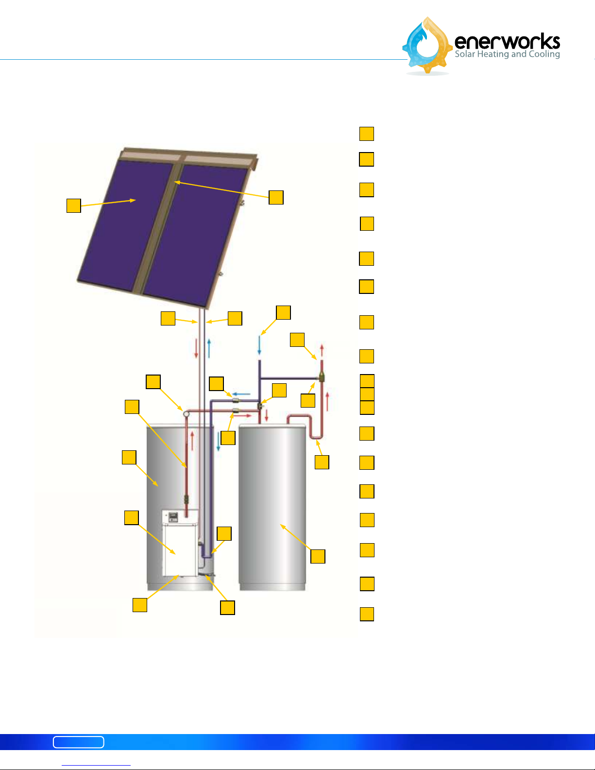
2.2 Pre-Heat Appliance Schematic
1
Solar collectors (1 to 4)
2
Line-set roof-penetration (behind flashing)
1
3 4
8
7
13
9
10
2
5
6
11
12
14
Heat transfer fluid line from collectors to
3
Energy Station (red – carries hot fluid)
Heat transfer fluid line from Energy Station to
4
collectors (blue – carries cool fluid)
5
Cold mains water supply (blue)
6
Hot water supply to home (red)
Thermosiphon loop,
7
solar-heated water to storage tank (red)
8
Thermometer
9
Bypass valves
10
11
12
13
(to isolate Appliance for service)
Anti-scald valve
(not included, may be required by code)
Solar storage tank
15
9
17
Fig. 2.2 EnerWorks Pre-Heat Solar Water Heating Appliance (with optional leaf-guard)
Module 4
14
18
16
14
Heat trap (U-bend limits heat loss)
15
Energy Station
Pre-existing or auxiliary hot water tank or
16
17
18
on-demand heater
Pressure relief valve (inside cover)
Thermosiphon loop feed (from storage)
5
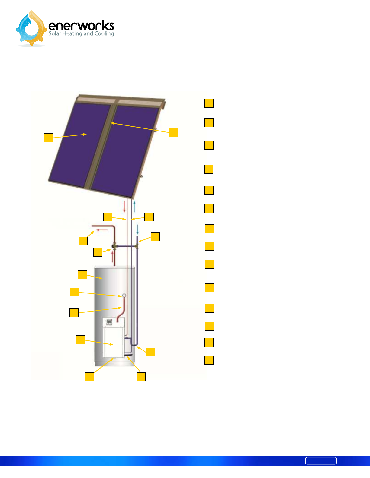
2.3 Single Tank Appliance Schematic (USA only)
Solar Collector
Installation Manual
1
Solar collectors (1 or 2)
2
1
3 4
5
6
8
9
7
2
Line-set roof-penetration (behind flashing)
Heat transfer fluid line from collectors to
3
Energy Station (red – carries hot fluid)
Heat transfer fluid line from Energy Station
4
to collectors (blue
5
Hot water supply to home (red)
6
Anti-scald valve (required)
7
Cold mains water supply (blue)
8
9
10
Solar storage tank with electric back-up
Thermometer
Thermosiphon loop,
– carries cool fluid)
solar-heated water to storage tank (red)
10
11
12
Fig. 2.3 EnerWorks Single Tank Solar Water Heating Appliance (with optional leaf-guard)
6
13
14
11
12
13
14
Energy Station
Pressure relief valve (inside cover)
Thermosiphon loop feed (from storage)
Heat trap (U-bend limits heat loss)
Module 4
Solar Collector
Installation Manual
3 - Site Evaluation
To achieve good performance and a good return on investment, the Appliance must be sized correctly
and it must be oriented properly. Site evaluation is necessary to determine whether a site is appropriate
and to evaluate the complexity of the installation. It is also necessary to determine the hot water loads,
number of individuals in a home, number of collectors and size of solar storage tank.
A site survey (see Appendix – Residential Site Survey) has been developed to assist installers in
evaluating potential installation locations. This can be removed from the Appendices and copied as
needed. Solar simulation software may assist in determining the best location and orientation for the
solar collectors.
For roof-mounting, installer should ensure that roof cladding or sheathing is in good repair. Also
ensure that rafters and trusses are adequate to support weight of solar collector(s) and mounting
assembly.
Building and plumbing permits and/or inspections may be necessary to proceed with installation.
Follow all code requirements and regulations.
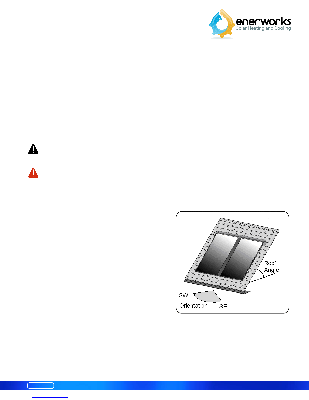
3.1 Collector Location, Orientation and Shading
Collector(s) should face as close to south as possible for
optimal performance. Within 45° of south is acceptable
as there is less than 10% loss (Fig. 3.1.1).
The roof angle from horizontal for optimal year-round
performance is equivalent to latitude of location plus or
minus 15°. A steeper angle provides better winter
performance as the sun is lower in the sky. Collectors will
also shed snow more effectively. A shallow angle
maximizes energy capture in summer when sun is high.
Be cautious of placement on low angle roofs due to
snow shedding and potential for ice-damming. A
minimum collector angle of 14° (3:12 pitch) is necessary
for stagnation-control device to function.
Shading of collectors greatly reduces performance.
When selecting installation location, consider potential
shading by trees and other buildings, especially
between peak solar hours of 10:00 and 15:00. A Solar
Pathfinder or similar device may be used to determine
potential shading throughout the year.
Module 4
Fig. 3.1.1 – Collector Orientation.
7
Solar Collector
Installation Manual
3.2 Available Roof Space
Appliance may consist of one to four collectors depending on required volume of hot water. Check
appliance specification sheet for sizing guidelines. Each collector is 4’ x 8’ (1.219 m x 2.438 m) and
must be mounted in “portrait” orientation. Installation area must be clear of roof vents, fans, satellite
dishes, etc. Refer to section 5.1 Locating rafters and positioning C-channel for more details.
3.3 Collector Racks
A rack may be used on the ground or to increase collector-angle on low-angled roofs. Consideration
must be given to wind and snow loads, and to aesthetics.
EnerWorks Solar Collectors are not as sensitive to orientation as photovoltaic panels (PV). Due to
size and weight of solar thermal collectors, tracking systems are not advisable.
Racking may require approval or certification by a building engineer and/or local authorities. It is
the responsibility of the installer to ensure appropriate design and safety criteria are met.
3.4 Line-Set
Line-set carries heat-transfer fluid from collectors to Energy Station and back again. Line-set must be
flexible, refrigeration-grade 3/8” soft-copper tube. A proper and dedicated bending tool must be used
for tight bends. Line should be as smooth as possible with no unnecessary fittings or bends. Site
evaluation should include examining location and difficulty of roof and wall penetrations. Appropriate
techniques and materials for sealing penetrations are necessary.
3.5 Location of Energy Station and Solar Storage Tank
Energy Station and solar storage tank will be located in mechanical or utility room, close to existing
water-heater. Stairway and doorway clearance must be examined. Additional floor space is
required for solar storage tank and Energy Station. Consideration must be given to location and
complexity of wall and ceiling penetrations, and to plumbing of appliance to existing water-heater
and to water distribution network.
Energy Station requires AC power. Solar storage tank and Energy Station must be installed in
proximity to AC outlet. Surge protection is recommended.
4 – Line-Set Installation
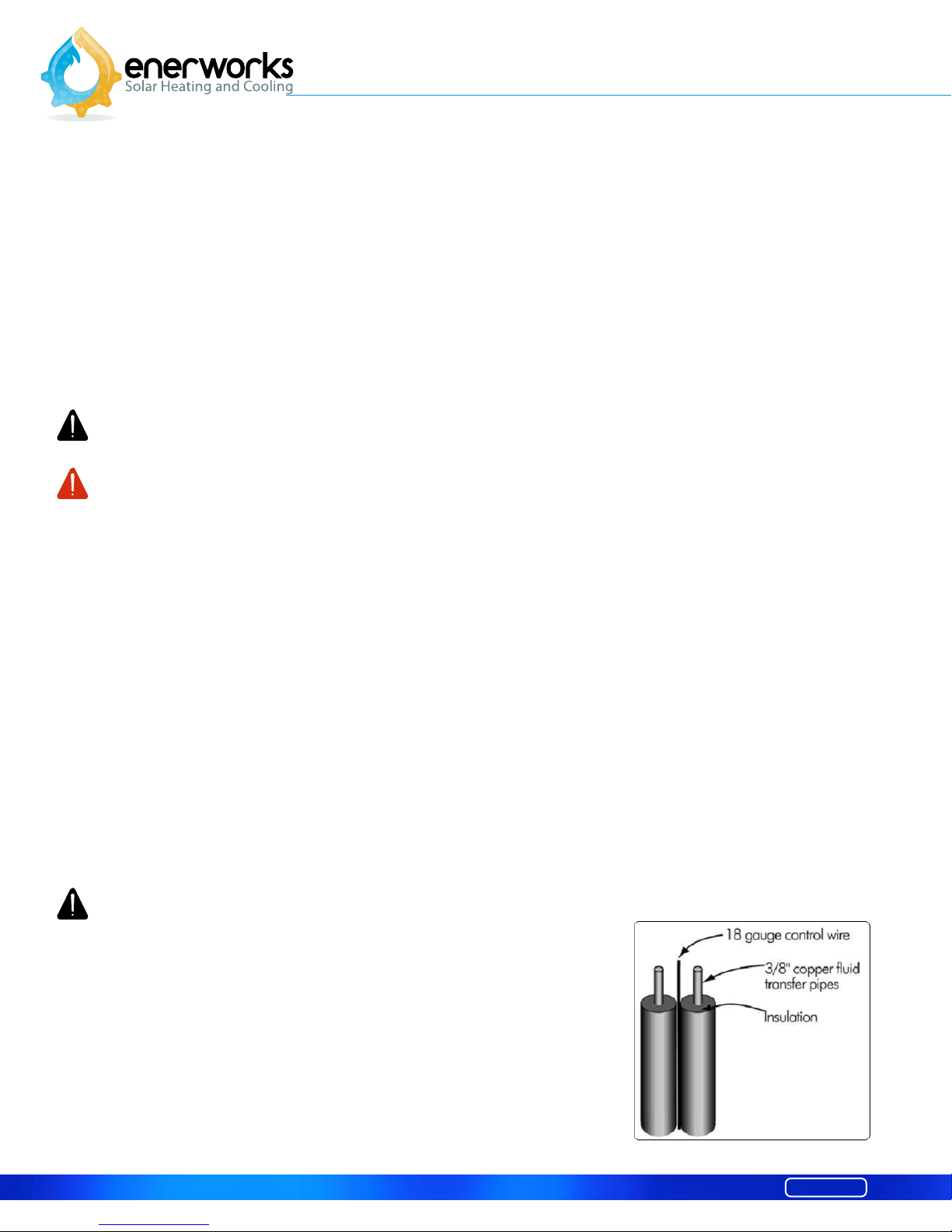
4.1 Line-set Description
Line-set connects Energy Station to solar collectors. Line-set consists of
two 3/8” refrigeration-grade, flexible soft-copper tubes. Tubes are
individually insulated with refrigeration insulation (3/8” ID - 3/8”-wall).
Bundle with the line-set an 18-gauge, two-conductor control wire that
connects the Energy Station Controller to the solar collector
temperature sensor (Fig. 4.1.1).
8
Fig. 4.1.1 – Line-set
Module 4
Solar Collector
Installation Manual
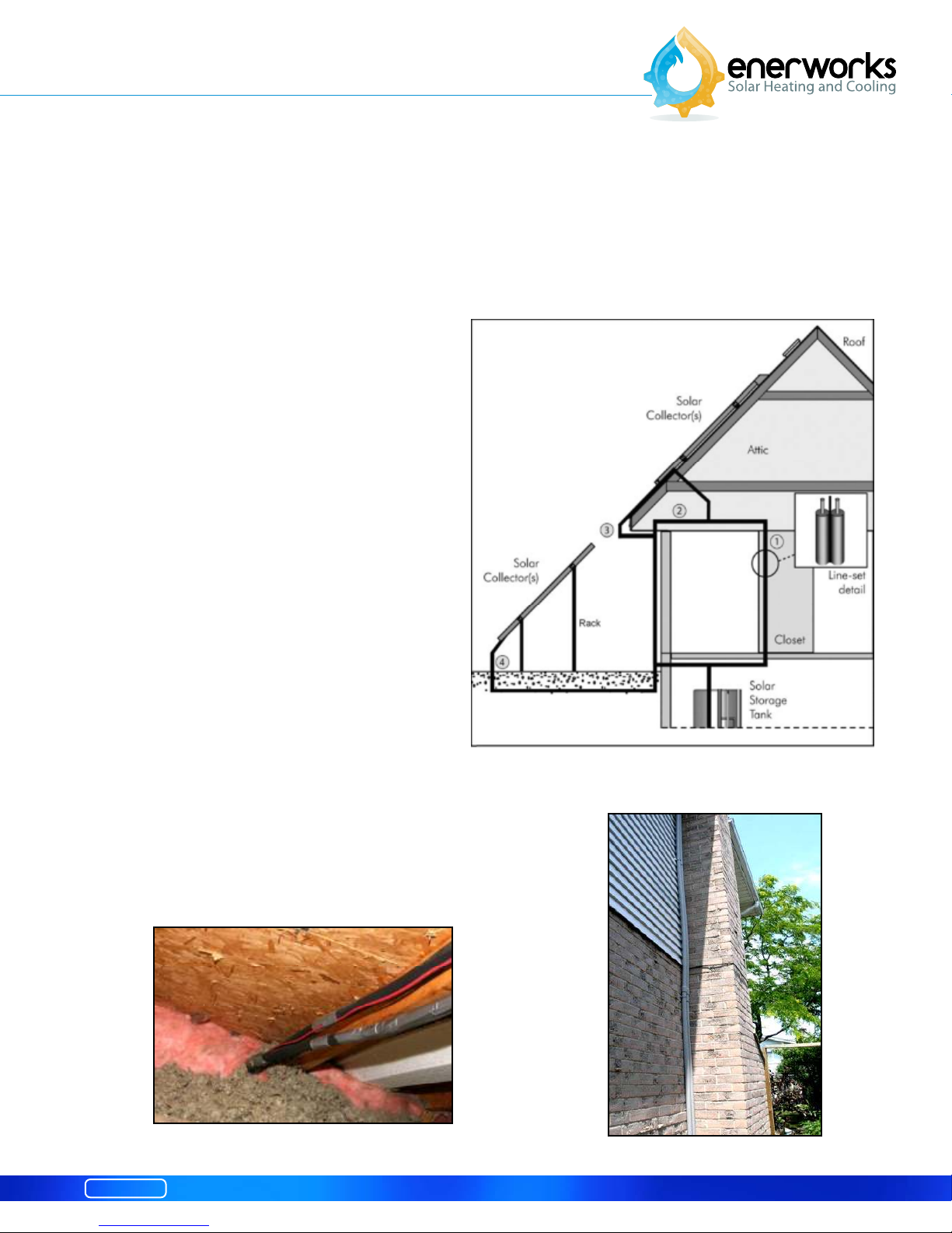
4.2 Line-Set Routing
Selection of line-set route should be discussed with homeowner with consideration to aesthetics,
complexity and cost of installation (Fig. 4.2.1). Line-set through home will have lowest heat-loss and
possibly shortest length (Fig. 4.2.1 option 1). Interior line-set should not run next to bedrooms or daytime living space as some vibration noise from pump may be transferred through line-set. Interior lineset may be more appropriate for bungalow or single-storey applications.
Line-set may penetrate roof into attic (Fig.
4.2.2) and drop from soffit down exterior
wall to above foundation or through
foundation to mechanical room (Fig. 4.2.1
option 2). This may facilitate installation and
minimize vibration noise transferred through
lines. Exterior line-set and insulation must be
protected by molding, electrical conduit or
false downspout that matches existing siding
or eavestrough (Fig. 4.2.3). Exterior line-set
may be best for two or three-storey
applications.
Line-set may run around eave and down
exterior wall if access to attic is limited (Fig.
4.2.1 option 3). All exterior insulation shall
be protected from ultraviolet radiation and
moisture damage. Line-set of rack-mounted
col lectors on ground may be run
underground through conduit such as big‘O’ to protect insulation (Fig. 4.2.1 option 4).
For new homes, consider installing 3 – 4” diameter PVC
or ABS chase from attic to hot-water tank location. This
will facilitate future removal or replacement of line-set if
necessary.
Fig. 4.2.1 – Line-set routes
Fig. 4.2.2 – Line-set and control-wire in attic.
Module 4
Fig. 4.2.3 – Exterior line-set in downspout
9
Solar Collector
Installation Manual
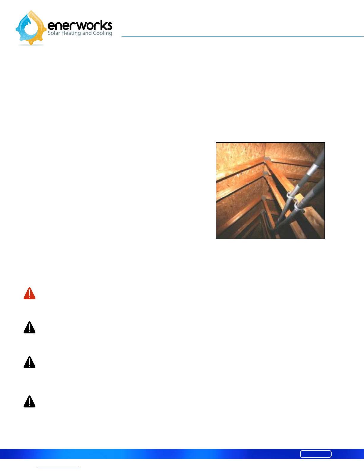
4.3 Line-Set Installation
Use care to unroll coiled copper tube. Leave protective end-caps in place to prevent contamination of heattransfer fluid. System degradation due to the contamination of fluid is not covered by warranty.
Seams should be taped with tape that will not dry out and disintegrate (i.e., duct tape). Lines may be pulled
as a bundled. Use straps to secure lines to rafters. Ensure straps are not in contact with copper lines due to
risk of galvanic corrosion (copper or plastic straps are recommended). Do not compress insulation when
bundling or securing lines (Fig. 4.3.1).
Line-set tube coils are available in 50’ and 75’ lengths.
Line-sets longer than 100’ are not recommended due to
the pressure drop through the system. It is best not to have
any joints or fittings. If line-set tube must be extended, do
not use lead or tin solder. The heat-transfer fluid will
degrade lead and tin solder, eventually causing leaks.
Brazing and flare union-fittings are permissible.
Wall, ceiling and roof-penetration may be a 2½” hole or
two 1¼” holes. Penetrations must be sealed appropriately
to maintain weather-proofing, sound-proofing, vermin
intrusion and fire integrity without impairing enclosure
functions. Roof penetration between collectors is
recommended as collector flashing hides line-set
penetration and eliminates need to protect insulation from
damaging UV.
When working in attics or confined spaces, determine type and quality of insulation material. Use
appropriate respirators or masks as necessary to prevent inhalation of insulation material.
A dedicated tube-bending tool must be used for tight bends. 3- and 4-collector
installations have tight tube bends on roof and a proper tube-bending tool is required. A proper
tube-bending tool may be necessary for 1- and 2-collector installations. A tube-bending tool is
recommended for line-set connections to Energy Station to provide clean, vertical lines.
Supply and return lines do not have to be differentiated. Control wire conductors do not have
to be differentiated.
Line-set must be insulated with refrigeration Insulation suitable for high temperatures such as
Armaflex, Aerocel or Gulf-O-Flex. Lower quality insulation (e.g. split foam tube) will degrade or
melt at high temperatures. Building materials must be insulated from elevated temperatures of
system components. Protective caps must be kept on ends of tubes until final connections are made
to prevent contamination of tubes and of heat-transfer fluid.
Fig. 4.3.1 – Line-set straps.
10
Module 4
 Loading...