

Enerwave ZW15SM-N User Manual
INSTALLATION NSTRUCTIONS
DESCRIPTION
The ZW15SM-N by itself is a Single Pole switch. Our unique wiring method combined
with Advanced Z-Wave technology allows for multiple switches (requires ZW3K-N) to
control a single Load manually at the devices or remotely from a computer, smart phone or
tablet in Real Time. The ZW15SM-N is fully compatible with other Z-Wave devices and it can be
added to most Z-Wave compliant controllers.
FEATURES
• Replaces a standard 120VAC, 15Amp wall switch with a technologically advanced switch
that can be manually controlled at the device or remotely through the Z-Wave network.
• Set scenes, schedule events (Program ON/OFF times like a timer), and even turn ON/OFF
when a motion or door sensor goes off.
• Can be used as a Single Pole switch or 3- Way (Multi-location) with ZW3K-N Auxiliary Switch
(sold separately).
• A blue LED night light can be programmed to come on when the load is ON or OFF.
• 3 Interchangeable Color Face Plates included (white, light almond, and black).
• Compatible with CFL, fluorescent, incandescent, and halogen bulbs.
• Measures energy usage of the connected load.
UPGRADING STANDARD SWITCHES TO Z-WAVE
REPLACING EXISTING SWITCHES WITH THE ZW15SM-N
Replacing a standard light switch with a smart Z-Wave switch is a simple way to modernize your home by adding programmable lighting control to your smart device. The ZW15SM-N
Smart Meter Switch enables you to measure the energy usage of your Lights. When added to a Z-Wave network, the ZW15SM-N reports real time data to your gateway or controller.
It can also display actual consumption (in W) and the accumulated power used (in kWh) in the user interface depending on the Hub. Please refer to your Hub manual for specific
instructions on measuring the power.
If you have trouble identifying the wires, STOP and
consult with an Electrician.
WIRING DIRECTIONS
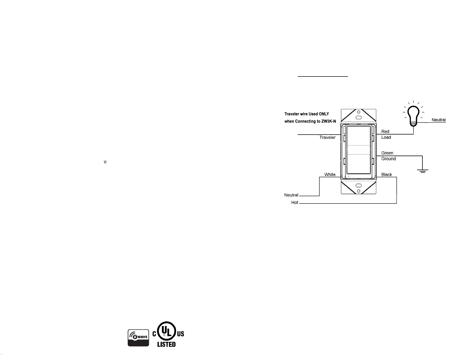
Step 1. Identify all your wires. Label the wires or draw a diagram of existing wires. Make
sure there is a NEUTRAL, HOT, and LOAD wire where the ZW15SM-N will be installed.
Step 2. Connect the wires according to the Diagram.
• Connect the BLACK wire on switch to the HOT wire.
• Connect the WHITE wire on switch to the NEUTRAL wire.
• Connect the Red wire on switch to the LOAD wire.
• Connect the GREEN wire on switch to the GROUND wire or
green GROUND screw on box.
To Replace the Face Cover,
use a small screwdriver to
pry off the cover
All three colors INCLUDED!
White
Light Almond
Black
For 3-Way installation, the ZW15SM-N requires the 3-Way
Control Auxiliary Switch ZW3K-N.
A standard 3-Way switch WILL NOT work with the ZW15SM-N.
Follow the ZW3K-N Instruction Manual for 3-Way installation.
REQUIREMENTS
Z-Wave devices require a connection to a compatible hub. Once the device is properly added to the hub, it can
be managed and customized to your needs. Please visit www.enerwaveautomation.com for a list of compatible
hubs. NEUTRAL wire is required.
SPECIFICATIONS
Voltage........................................................................................................ 120VAC, 60Hz
Incandescent............................................................................................................1000W
Ballast.....................................................................................................................1200VA
Resistive..........................................................................................................1800W(15A)
Motor........................................................................................................................ 1/2 HP
Operating Temperature....................................................................................... 32-104° F
Z-Wave Frequency.......................................................................................... 908.42 MHz
Range.........................................................................................Up to 100 feet line of sight
........................between the Wireless Controller and the closest Z-Wave receiver module.
FCC COMPLIANCE STATEMENT
FCC Grant of Equipment Authorizations of this device and transmitters installed in this device can be found at FCC website by entering the FCC ID number on the device.
Caution: Changes or modifications not expressly approved by the part responsible for compliance could void the user’s right to operate the equipment.
This device complies with Part 15 of the FCC Rules. Operation is subject to the following two conditions: (1) this device may not cause harmful interference, and (2) this device must accept
any interference received, including interference that may cause undesired operation of the device.
This equipment has been tested and found to comply with the limits for a Class B digital device, pursuant to part 15 of the FCC rules. These limits are designed to provide reasonable
protection against harmful interference in a residential installation. This equipment generates, uses and can radiate radio frequency energy and, if not installed and used in accordance with the
instructions, may cause harmful interference to radio communications. However, there is no guarantee that interference will not occur in a particular installation. If this equipment does cause
harmful interference to radio or television reception, which can be determined by turning the equipment off and on, the user is encouraged to try to correct the interference by one or more of
the following measures:
• Reorient or relocate the receiving antenna.
• Increase the separation between the equipment and receiver.
• Connect the equipment into an outlet on a circuit different from that to which the receiver is connected.
• Consult the dealer or an experienced radio/TV technician for help.
WARNING: Turn the POWER OFF at the circuit breaker before installing the Switch
Read and understand these instructions before installing. This device is intended for installation in accordance with the National Electric Code and local regulations. It is recommended that a qualified electrician performs this installation. Make sure to turn off the circuit breaker or fuse(s)
and make sure power is off before wiring the device. Exercise extreme caution when using Z-Wave devices to control appliances. Operation of the Z-Wave device may be in a different room than the controlled appliance so an unintentional activation may occur if the wrong button on the
remote is pressed. Z-Wave devices can be automatically powered on by programmed events. Unattended or unintentional operation could result in hazardous conditions. Z-Wave enabled devices should never be used to supply power to, control or monitor medical and/or life support
equipment. To enable the 3-way function install the ZW3K-N in conjunction with the ZW15SM-N. For use with incandescent, halogen, and CFL lights. Use copper wires only.
Model: ZW15SM-N
Wireless Home Automation Control
ON/OFF Switch with Smart Meter
WARRANTY INFORMATION
This device is warranted to be free of material and workmanship defects for 2 years from the date of
purchase. Original receipt or proof of purchase from an authorized retailer must be presented upon warranty
claim. ALL claims must be verified and approved by Enerwave, Inc. Warranties from other Enerwave
products may vary. This warranty is nontransferable and does not cover normal wear and tear or any
malfunction, failure, or defect resulting from misuse, abuse, neglect, alteration, modification, or improper
installation. To the fullest extent permitted by the applicable state law, Enerwave shall not be liable to the
purchaser or end user customer of Enerwave products for direct, indirect, incidental, or consequential
damages even if Enerwave has been advised of the possibility of such damages. Enerwave’s total liability
under this or any other warranty, express or implied, is limited to repair, replacement or refund. Repair,
replacement or refund are the sole and exclusive remedies for breach of warranty or any other legal theory.
© 2016 Enerwave Home Automation ● WWW.ENERWAVEAUTOMATION.COM ● CA, USA
0207160033
PROGRAMMING
WIRELESS RANGE
This device complies with the Z-Wave standard of open-air, line of sight transmission distances of 100 feet.
Actual performance in a home depends on the numbers of walls between the remote controller and the
destination device, the type of construction and the number of Z-Wave enabled devices installed in the control
network. Most Z-Wave enabled devices act as signal repeater and multiple devices result in more possible
transmission routes which helps eliminate " RF dead-spots." Use the following chart only as a guide to
maximize the signal range.
OPERATING THE ZW15SM-N
You're now ready for basic operation of the ZW15SM-N. The
switch turns the Load (Lights) ON/OFF when the ON/OFF rocker
switch is pushed. It can also be operated from your desktop or a
ADVANCED PROGRAMMING
WARNING: Advanced programming is recommended ONLY for experienced programmers. The ZW15SM-N has customizable features/ functions that require writing codes. Changes to code may
cause device to function improperly or to not function at all.
The following parameters require that you have an advanced controller. Basic remotes do not have this capability.
All-ON and All-OFF
Depending upon your primary controller, the ZW15SM-N switch can be set to respond to ALL-ON and ALL-OFF commands in four different ways. Some controllers may not be able to change the
response from its default setting. Please refer to your controller’s instructions or technical support for information on whether or not it supports the configuration function and if so, how to change this
setting. The four possible responses for each button (top or bottom button on switch) are:
- Push button will respond to ALL-ON and the ALL-OFF command (default).
- Push button will not respond to ALL-ON or ALL-OFF commands.
- Push button will respond to the ALL-OFF command but will not respond to the ALL-ON command.
- Push button will respond to the ALL-ON command but will not respond to the ALL-OFF command.
LED Light and Buttons Configuration
By default, one press of the "up" button will turn the Load on and the LED indicator will
turn off. Use "Command_Class_Configuration" to configure the LED indicator to operate in
reverse when the button is pressed.
Configuration details
• Parameter 1 (configure LED light state ), default value is 0. Valid values
are 0 and 1 with 1 byte.
• Parameter 2 (configure button toggle), default value is 0. Valid values
are 0 and 1 with 1 byte.
smart device such as the iPhone, iPad or any Android device.
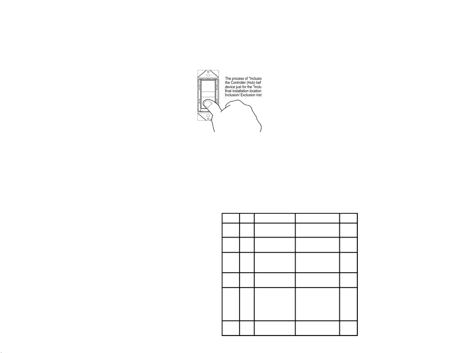
DEVICE INCLUSION/ EXCLUSION
The process of "Inclusion/ Exclusion" is to Add or Remove the device from the Hub. All Z-Wave devices must be "Included" on
the Controller (Hub) before it can be controlled from a smart device. The Hub should be brought physically closer to the
device just for the "Inclusion" process (recommended within 10ft). When finished, the Hub and device can be moved back to
final installation location. Download the App or log onto the website associated with the Hub you are using and follow their
Inclusion/ Exclusion instructions as each Hub's programming and features are different.
Parameter
NO.
Size
1 Byte
1
1 Byte
8
1 Byte
9
1 Byte
10
1 Byte
11
1 Byte
12
• During the Inclusion/ Exclusion process, the ON/OFF switch is used for including/ excluding the device.
• It is best to perform an Exclusion of the device prior to performing an Inclusion.
Step 1. From the Control Panel, go the the device Exclusion page.
o Select "Exclude Device".
o When prompted, press the "ON" or "OFF" Button on the switch.
Step 2. Go to the "Add Device" page.
o Select "Include Device".
o When prompted, press the "ON" or "OFF" Button on the switch.
The primary controller should indicate that the action was successful. If the controller indicates the
action was unsuccessful, please repeat from Step 1.
Once the switch is part of the network, the same basic procedure is used to add the switch to groups &
scenes or change advanced functions. Refer to the primary controller’s instructions for details.
Step 3. Follow the On-Screen instructions in the Control Panel on adding or
removing rooms, scenes, other devices, and other functions and features.
Description
synchronization of load
power and LED indicator
Instant Energy Autosend
Interval
(send METER_REPORT)
Instant Energy Autosend
Interval
(send
SENSOR_
MULTILEVEL_REPORT)
Accumulated Energy
Autosend Interval report
(send METER_REPORT)
Enable automatic
notifications to
associated device
whenever there
is a wattage change
Minimum change in
wattage report
Valid Value
0: Power on, LED off
1: Power on, LED on
0: not send
0: not send
255: 1-255 Min
1-1-255: 1-255 Min
0: not send
1-255: 1-255 Min
0: not send
1-255: 1-255 Min
0: Not report
(METER_REPORT) only
1: Send
(SENSOR_MULTI
2: Send
LEVEL_REPORT) only
3: Send both
REPORT) and
MULTILEVEL_
(METER_
(SENSOR_
REPORT)
0-255: 0.0-25.5W
Default
Value
Default=0
Default=0
Default=0
Default=0
Default=1
Default=10
ZW15SM-N
 Loading...