


ENERVEX
GSV 009-016 GREASE FAN
3001361 08.17 Installation & Operating Manual
READ AND SAVE THESE INSTRUCTIONS!
ENERVEX Inc.
1685 Bluegrass Lakes
Parkway
Alpharetta, GA 30004
USA
P: 770.587.3238
F: 770.587.4731
T: 800.255.2923
info@enervex.com
www.enervex.com

3001361 08.17
!
The GSV 009-016 Grease Fan is ETL Listed in the U.S. and Canada.
Symbol Legend
The following terms are used throughout this manual to bring
attention to the presence of potential hazards, or to important
information concerning the product.
DANGER: Indicates an imminent
hazardous situation which, if not
avoided, will result in death, serious
injury or substantial property damage.
WARNING: Indicates an imminent
hazardous situation which, if not
avoided, may result in personal injury
or property damage.
How to use this manual
This installation manual does not contain any system design
documentation. System design documentation is available
from any authorized ENERVEX representative. Accessories,
fans, and variable frequency drives are not covered by this
manual. Please refer to these component’s individual manuals.
TO REDUCE THE RISK OF FIRE,
ELECTRICAL SHOCK OR INJURY TO
PERSONS, OBSERVE THE FOLLOWING:
TO REDUCE THE RISK OF INJURY TO
PERSONS IN THE EVENT OF A CHIMNEY
FIRE, OBSERVE THE FOLLOWING:
1. Immediately close all dampers and/or air entrance
openings to the cooking appliance. This includes doors.
2. Alert your patrons to the possible danger.
3. Inspect your cooking appliance and chimney surroundings
for possible fire. If in doubt, alert your fire department.
4. Do not continue to use your appliance until it and your
chimney have been throroughly inspected. Overheating
can cause metal parts to expand, buckle and crack. If
you are not certain, have a certified chimney sweep disassemble all parts so they can be inspected and cleaned.
5. Do not use salt or water on the fire in the cooking appliance. Salt is corrosive and water will cause a dangerous
steam explosion. You might be able to control the fire by
using ashes, sand or baking soda, since baking soda is an
ingredient used for dry chemical fire extinguishers.
6. After a chimney fire, when it is safe to do so, check internal locations such as an attic and under the roof and keep
watching for two or three hours. There may be delayed
smoldering and subsequent ignition, even if the fire inside
the chimney has been controlled.
1. Use this unit in the manner intended by the manufacturer.
If you have questions, contact the manufacturer at the
address or telephone number listed on the front of the
manual.
2. Before servicing or cleaning the unit, switch off at service
panel and lock service panel to prevent power from being
switched on accidentally.
3. Installation work and electrical wiring must be done by a
qualified person(s) in accordance with applicable codes
and standards.
4. Follow the appliance manufacturer’s guidelines and safety
standards such as those published by the National Fire
Protection Association (NFPA), and the American Society
for Heating, Refrigeration and Air Conditioning Engineers
(ASHRAE), and the local code authorities.
5. This unit must be grounded.
TO REDUCE THE RISK OF A CHIMNEY FIRE:
1. Keep chimney and grease fan clean.
2. Always turn ON fan when using the cooking appliance.
3. Do not leave cooking appliance unattended when in use.
CAUTION
Please read specification label on product for further
information and requirements.
2

Content
1. PRODUCT INFORMATION
1.1 Function ............................................................4
1.2 Components .....................................................4
1.3 Shipping ...........................................................5
1.4 Warranty ...........................................................5
2. SPECIFICATIONS AND DIMENSIONS
2.1 Dimensions and Capacities ...............................6
3. MECHANICAL INSTALLATION
3.1 Positioning ........................................................7
3.2 Installation on Steel Duct ...................................7
3.3 Installation on Roof Curb ...................................8
3.4 Installation on Side Wall ....................................8
3.5 High Temperature Applications ..........................8
4. ELECTRICAL INSTALLATION
4.1 Electrical Requirements .....................................9
4.2 Wiring Diagram .................................................9
5. STARTUP AND CONFIGURATION
5.1 System Testing .................................................10
5.2 Testing Pizza Oven Operation ...........................10
5.3 Adjusting Fan Speed .........................................10
5.4 Operation of Pizza Ovens ..................................11
6. MAINTENANCE AND TROUBLESHOOTING
6.1 Care and Cleaning ............................................12
6.2 Chimney Cleaning Intervals ...............................12
6.3 Creosote Formation and Need for Removal ......12
6.4 Inspection Schedule .........................................13
6.5 Chimney Fires and What to Do About Them .....14
6.6 Spare Parts Ordering ........................................15
6.7 Troubleshooting ................................................16
3001361 08.17
3

3001361 08.17
1. PRODUCT INFORMATION
1.1 FUNCTION
ENERVEX Model GSV Grease Fan is designed to provide a
large exhaust volume at a high discharge velocity.
It is intended for use as a part of a restaurant exhaust system
for solid fuel cooking appliances and grease applications
according to NFPA96.
The use of the ENERVEX Grease Fan is not restricted to any
type of chimney or grease duct. However, always follow the
solid fuel appliance manufacturer’s instructions regarding the
venting.
The GSV is suitable for use with natural gas, LP-gas or solid
fuel.
The fan is designed to create a mechanical draft in chimney
and grease duct systems. It can also be used to increase
the capacity or efficiency of such a system.
The housing is made in heavy cast aluminum and can
be opened for easy cleaning. The axial vane is made of
stainless steel and is completely in balance.
The motor is a direct-drive, variable speed, class H insulated,
high temperature motor. It has permanently lubricated and
sealed ball bearings and is maintenance free.
Installation must conform to the requirements of the authority
having jurisdiction. Where required by the authority
having jurisdiction, the installation must also conform to the
NFPA54, NFPA96 or NFPA211.
All electrical wiring must be in accordance with the
requirements of authority having jurisdiction or, in
absence of such requirements, with the National Electrical
Code, NFPA70.
ENERVEX Model GSV is tested and listed to UL Standard
705 for Power Ventilators and UL Standard 762 for Power
Ventilators for Restaurant Exhaust Ventilators.
The model is also tested and listed to ULC-S645-93,
Standard for Power Roof Ventilators for Commercial and
Institutional Kitchen Exhaust Systems.
1.2 COMPONENTS
The GSV Grease Fan consists of the following components
a. Top section
b. Bottom section
c. Motor
d. Axial vane
e. Inlet for impeller
f. Locking hinge
g. Bird screen
h. Carrying handle
h. Wiring conduit
Fig. 1
Max. 575°F (300°C)
Fig 1
4

1.3 SHIPPING
!
The fan is shipped in a corrugated cardboard box. A
transport securing device may be attached to the bottom
of the fan to hold the motor and impeller in place. Do not
remove the device until the fan is at the installation point.
Do not remove the transport securing device
until the fan is being installed on the duct or the
roof curb. The motor shaft could be damaged.
STANDARD
Fan with flexible conduit terminating 2" x 4" x 4" weather
tight junction box.
PACKING LIST
If other components are shipped, these will appear on the
shipment packing list.
NOTE: All single phase fans are shipped with a capacitor and
junction box connected via conduit. The capacitor is located
INSIDE the junction box. Please do not discard.
3001361 08.17
1.4 WARRANTY
2-Year Factory Warranty. Complete warranty conditions are
available from ENERVEX, Inc.
Adequate fresh air must be provided
for combusion; otherwise, improper
operation and inadequate venting of
deadly flue gases may result.
If you are installing the fan on an existing
chimeny system or grease duct, you
must clean the chimney or duct prior to
installation.
Always use a certified chimney sweep,
certified by the Chimney Safety Institute of
America (CSIA) to clean the chimeny, duct
and grease fan.
5

3001361 08.17
2000
Ps (in H20)
Volume (cfm)
30
2000
Height (feet)
Volume (cfm)
2. SPECIFICATIONS AND DIMENSIONS
2.1 DIMENSIONS AND CAPACITIES
Specifications
Model GSV 009 GSV 012 GSV 014 GSV 016
Discharge Vertical
Fan Type Axial Vane
Max. Discharge
Velocity
Actual Discharge
Velocity
Voltage V AC 1x120
RPM 1600
Amps A 0.5 1.4 2.9 5.8
CFM @0.0 Ps 375 875 1550 1740
Motor Output kW / HP 0.025 / 0.03 0.13 / 0.10 0.21 / 0.16 0.47 / 0.35
Weight lbs / kg 28 / 12 46 / 18 60 / 26 86 / 35
A in / mm 9.85 / 250 11.03 / 280 13.20 / 335 14.97 / 380
B x B in / mm 12.21 / 310 15.37 / 390 19.11 / 485 22.85 / 580
Dimensions
C x C in / mm 9.46 / 240 12.22 / 310 15.17 / 385 18.32 / 465
D in / mm 8.63 / 219 10.72 / 272 13.04 / 331 14.26 / 362
E in / mm 2.76 / 70 3.15 / 80 3.94 / 100 4.53 / 115
Soft Start Required No No No No
Variable Speed Motor Yes Yes Yes Yes
Temperature Rating 575°F/300°C
FPM 2351 2592 2593 2169
FPM 5.9xCFM 2.9xCFM 1.9xCFM 1.2xCFM
A
E
D
C
B
Sound Diagram
Model
GSV 009 57 55 54 49 40 35 26 26
GSV 012 64 62 61 55 51 46 40 33
GSV 014 71 70 68 61 56 44 44 40
GSV 016 76 76 70 65 60 49 49 44
Lw dB (measured in accordance with ISO 3744)
125Hz 250Hz 500Hz 1000Hz 2000Hz 4000Hz 8000Hz
Lp dB(A)
Capacity Plume Height
1.0
0.9
0.8
0.7
0.6
0.5
0.4
0.3
0.2
0.1
0
GSV 012
GSV 009
500 750 1000 1250 1500 1750
2500
GSV 016
GSV 014
27
24
21
18
15
12
9
6
GSV 009
3
0
2500
GSV 014
GSV 012
500 750 1000 1250 1500 1750
GSV 016
a Top Section
b Bottom Section
c Motor
d Axial Vane
Hinged housing
e Inlet for Impeller
f Locking Hinge
g Wiring Conduit
h Handle
6

3. MECHANICAL INSTALLATION
3.1 POSITIONING
Considered a mechanical draft system, there are much
different code requirements than for a gravity venting system
or grease ducts used with gas or solid fuel applications. As
a general rule, the mechancal draft system must be installed
min. 3 feet away from any forced air inlet located within
10 feet, and min. 4 feet away from anydoor or window.
For complete information, consult ENERVEX or your local
building codes.
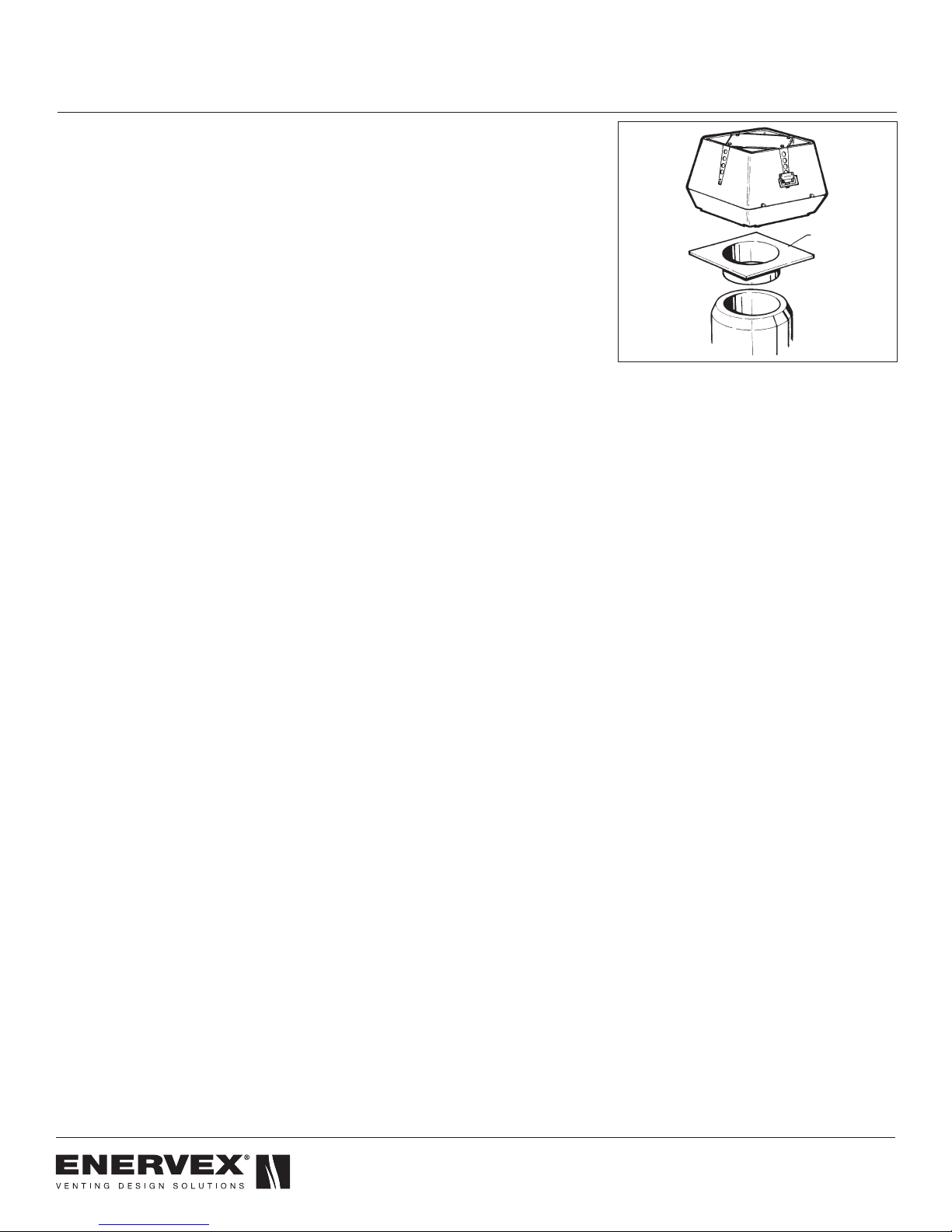
3.2 INSTALLATION ON STEEL DUCT
• Insert the steel chimney adapter into the chimney where
the long collar engagement ensures safeanchoring (see
Fig. 2). If necessary, the adapter can be secured by means
of long self-tapping stainless steel screws into the side of
collar through the chimney wall. Do not obstruct the flow.
• Turn the fan upside-down and lay a bead of hi-temp silicon
on the base close to the outer edge (not shown).
• Remove the transport securing device (if present) holding
the motor shaft and impeller in place.
• Place the fan on the adapter with the fan inlet centered
over the chimney outlet.
• Open the fan and secure the fan onto the adapter, through
the pre-drilled holes in the bottom, with lag bolts or self-
tapping sheet metal screws, one at each corner.
• Seal around the fan base to make sure it is watertight and
no water can slip in between the fan and the adapter. Do
not block the 4 drain holes.
3001361 08.17
Steel
Chimney
Adapter
Fig 2
7
3001361 08.17
3.3 INSTALLATION ON ROOF CURB
If the fan is installed on a roof curb, the curb will do the same
as the adapter. Follow the instructions under 3.2.
3.4 INSTALLATION ON SIDE WALL
• Make sure the vent terminates flush with the wall. Insert
the steel chimney adapter and secure it safely to the wall.
Seal around the edges of the adapter flange.
• Mark the locations of the wall anchors and predrill holes
for them.
• Turn the fan upside-down and lay a bead of hi-temp
silicone on the base close to the outer edge (not shown).
• Open the fan and secure the fan onto the adapter with
wall anchors, through the pre drilled holes in the bottom.
Make sure the conduit is located on one of the sides.
Never on the upside or downside.
• Seal around the fan base to make sure it is watertight and
no water can slip in between the fan and the adapter. Do
not block the 4 drain holes.
3.5 HIGH TEMPERATURE APPLICATIONS
• If the fan is used for applications that exceed its
temperature rating, dilution bolts must be used.
• Install the dilution bolts in the outer holes of the fan base.
• Adjust the height of the dilution gap by adjusting the
dilution bolts, so the temperature of the exhaust going
through the fan does not exceed the fan’s temperature
rating.
• Be aware the dilution bolts will have a negative impact on
the fan’s actual capacity and a stronger fan model may
be required. For more information, please refer to the
installation manual accompanying the dilution bolts.
Fig. 2
Steel
Chimney
Adapter
Fig 3
8

4. ELECTRICAL INSTALLATION
!
Refer to Fan Speed Contr
L1 N
To fan
Red
Green
4.1 ELECTRICAL REQUIREMENTS
Power requirements depend on the fan size. They can be
found on page 6.
DANGER
Turn off electrical power before servicing.
Contact with live electric components
can cause shock or death.
NOTICE
If any of the original wire supplied with the
system must be replaced, use similar wire
of the same temperature rating. Otherwise,
insulation may melt or degrade, exposing
bare wire.
4.2 WIRING DIAGRAM
The connection diagram below shows how the fan is
connected to the fan speed control and the power source
(see Fig. 4).
Use 2-conductor wire of minimum 14 AWG with ground.
3001361 08.17
FAN
MOTOR
Black
White
Green
M2M1
PE
wiring diagram
Red
Capacitor
Junction Box
supplied by contractor
Repair Switch
ol
Fig 4
M2
M1 PE
Fan Speed Control
Power Supply
1x120V AC
Wire Nut
Factory Wired
Not Connected
Field Wiring
Connected
9
3001361 08.17
5. STARTUP AND CONFIGURATION
5.1 SYSTEM TESTING
• Check the line voltage with the motor nameplate rating.
• Determine if the axial vane or impeller is running free
and has not been subject to misalignment in shipping or
installation.
• Turn the grease fan ON and make sure that it is operating.
Adjust the fan speed control to make sure it is operating
properly.
DANGER
Prior to using a cooking appliance,
make sure that sufficient air needed for
proper combustion and exhausting of
gases from oil/gas-fired appliances, like
water heaters, furnaces and boilers, is
provided.
• With the fan ON, check that other heating appliances
(furnace, water heater, etc.) are operating safely without
spillage (spillage is the escape of flue gases from the relief
opening of the draft hood of an atmospheric appliance.)
On start-up, a little spillage is normal, but it must stop
after a couple of minutes.
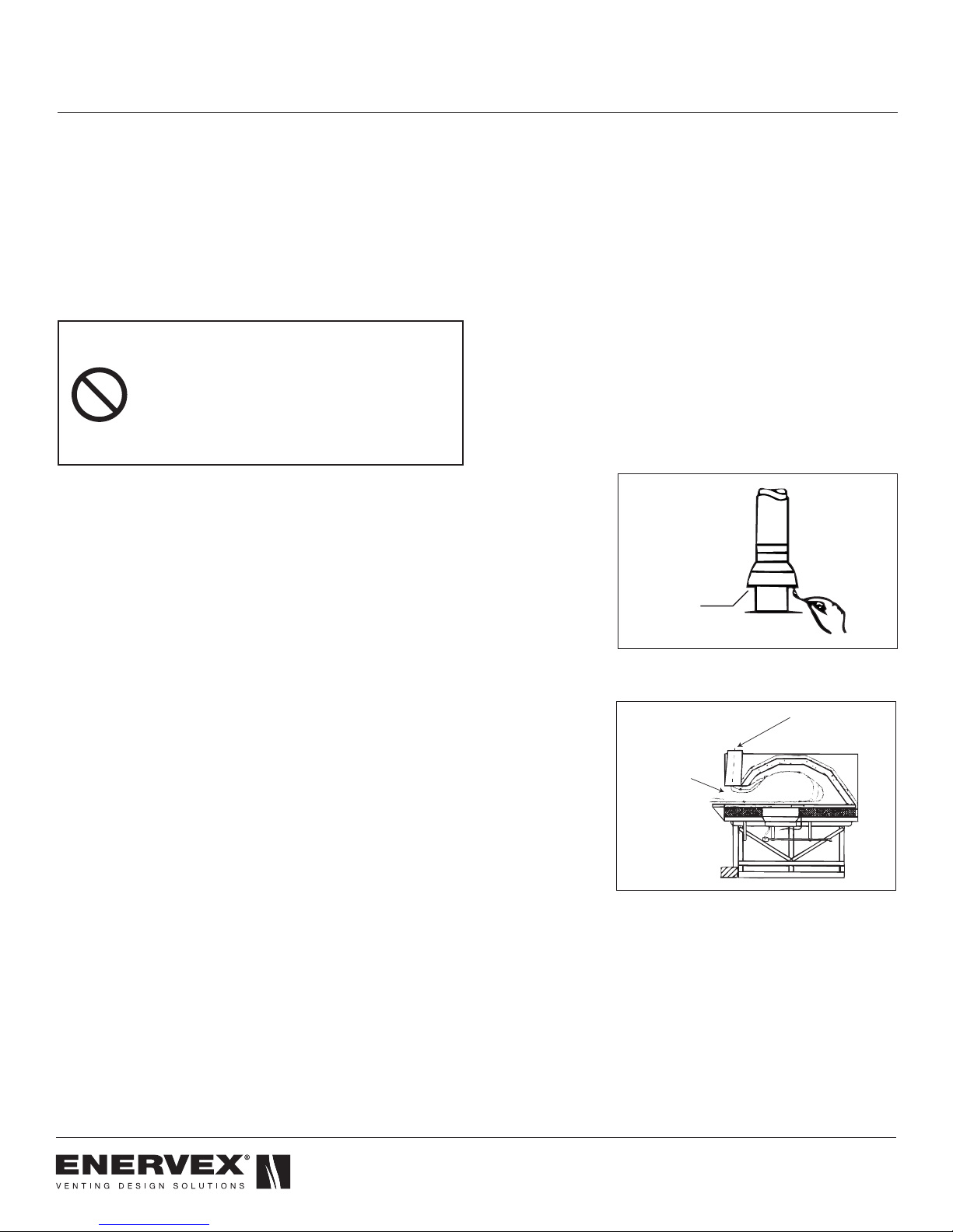
• Spillage can be detected by introducing smoke into the
flue products ahead of the draft hood or by observing if
the flame of a match goes out when it is held at the edge
of the draft relief opening (see Fig. 5).
5.2 TESTING PIZZA OVEN OPERATION
Most pizza ovens consist of a dome with a front opening
that can be closed with a cast iron door. Above the opening,
a hood connected to the flue assures smoke and odors are
collected and removed safely (see Fig. 6).
Place a few logs in the back of the dome and set the fan at
high/full speed. Light the fire. Turn on all exhaust fans (range
hoods, etc.) and make sure that there is no spillage from the
hood into the room. When the fire has caught on, reduce the
speed of the grease fan to a point where it still removes the
flue gases safely. Mark this setting on the fan speed control
cover, as this will be the operating position/speed of the
grease fan.
5.3 ADJUSTING FAN SPEED
Start all heating appliances connected to the chimney fan
installed. Set the fan speed control to the speed where no
spillage is experienced anywhere in the system.
Drafthood
Relief Opening
Fig 5
Flue connection
Check for
spillage here
Fig 6
10

5.4 OPERATION OF PIZZA OVENS
!
Prior to starting a fire, set the fan at high/full speed and start
the fire following the oven manufacturer’s instructions or, in
the absence of such instructions, follow normal instructions
on burning a fire in a fireplace or stove.
After the fire catches on, after 3-5 minutes, reduce the speed
of the grease fan to a level where it safely removes the flue
gases and a perfect flame can be maintained.
When adding wood to the fire, it may be necessary to
increase the fan speed for a short period of time.
Do not over-fire the pizza oven. Small deposits
of creosote could be ignited and start a small
chimney fire which could cause the chimney
flue to reach a hazardous temperature.
3001361 08.17
11
3001361 08.17
!
6. MAINTENANCE AND TROUBLESHOOTING
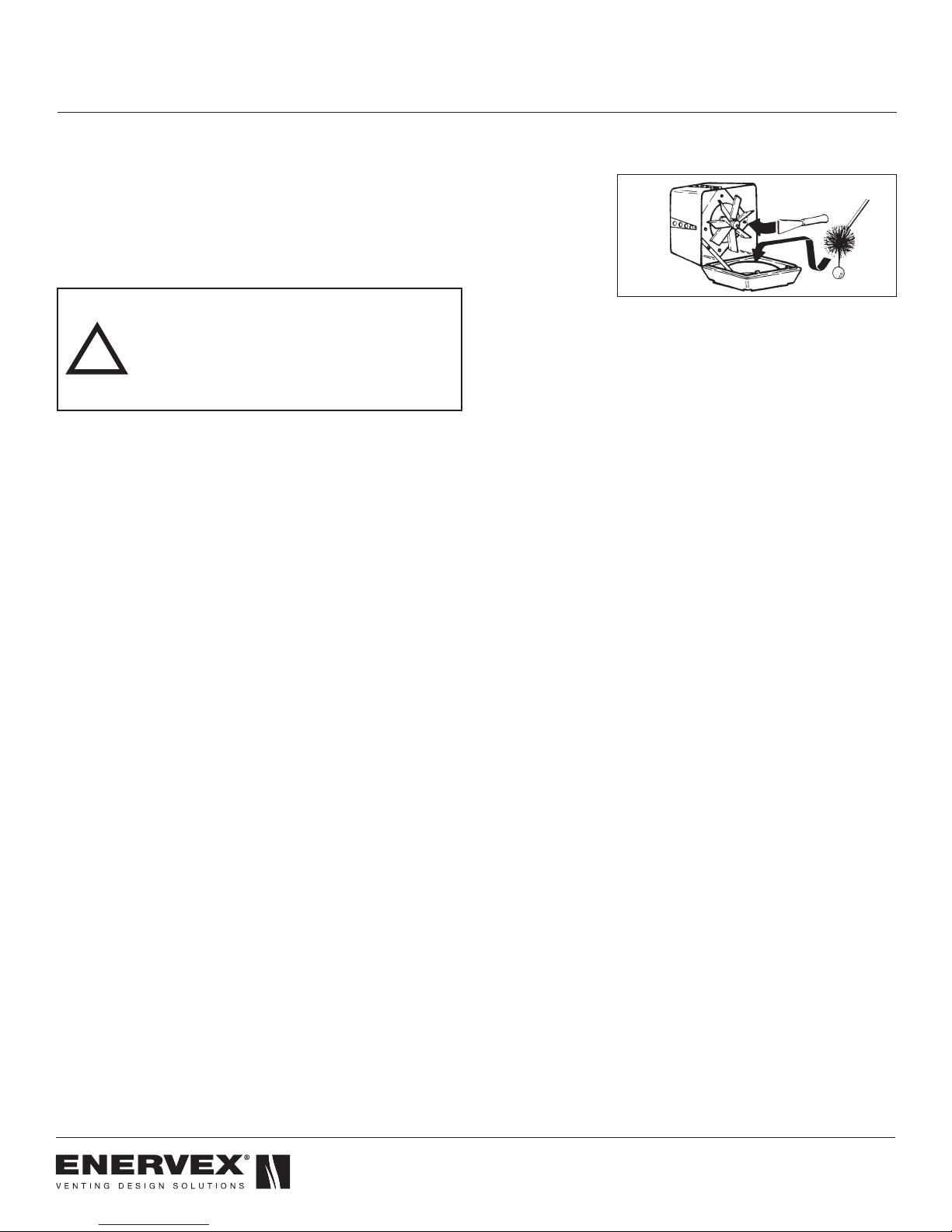
6.1 CARE AND CLEANING
The ENERVEX Grease Fan is designed for prolonged use.
The fan should be inspected at least once a year when the
chimney is inspected. Deposits should be removed from
the fan blades or the impeller and the bottom of the motor
housing. The top of the fan is hinged and can be opened in
order to ease the cleaning. See Fig. 7.
WARNING
Do not open the motor housing unless power
to the chimney fan has been disconnected.
6.2 CHIMNEY CLEANING INTERVALS
The need for chimney and chimney fan maintenance
depends on how the cooking appliance is operated.
Pizza ovens and BBQs need a great deal of chimney and
chimney fan maintenance. These appliances produce dense
smoke consisting of creosote and grease if it is loaded for
long durations or overnight fires.
6.3 CREOSOTE FORMATION AND NEED FOR
REMOVAL
When wood is burned slowly, it produces tar and other
organic vapors, which combine with expelled moisture to
form creosote. The creosote vapors condense in the relatively
cool chimney flue of a slow-burning fire. As a result, creosote
residue accumulates on the flue lining. When ignited, this
creosote makes an extremely hot fire.
Creosote causes many problems. Some are visible, while
others are not.It can make trouble if:
1.) It runs down outside the pipe to damage the finish on the
metal.
2.) It drips out of joints, damaging floors or furnishings.
3.) It plugs up the chimney causing poor combustion,
smoking, soiling walls and indoor pollution.
4.) It catches fire in the chimney to cause possible chimney
damage and damage to the building.
Fig 7
12
!
!
6.4 INSPECTION SCHEDULE
The chimney and the chimney fan should be inspected
at least every 2 weeks for the first couple of months to
determine at what rate the creosote builds up. If creosote has
accumulated, it should be removed to reduce the risk of a
chimney fire.
Evaluation of chimney systems installed in
commercial restaurants serving a wood-fired
cooking appliance indicates a build-up of 1/8"
- 1/4" of creosote for every 4 cords of wood
burned. This can be used as a guideline, but
each application is different.
As a guideline, a chimney and grease fan serving a
commercial wood-fired cooking appliance should be cleaned
at least once a month, unless the use has proven this to be
more than adequate.
Most chimney manufacturers require, if you see deposits
more than 1/16" thick, clean all chimney parts mechanically.
This means using brushes, scraping or equivalent.
3001361 08.17
Don’t start a chimney fire as a means to
clean the chimney!
With only slight deposits, try a hot fire to see if the black
deposits fall down the chimney. You can hear the sound of
falling deposits when the temperature conditions are right.
Afterwards, reinspect the chimney and the inside of the oven
for deposits.
Do not use chemical cleaners, they may corrode the inside
of the chimney. They may or may not prevent or remove the
creosote. When they are used together with a hot fire, it is
probably the fire that is doing the work.
Depending on the rate of build-up, as you learn what is going
on in the chimney, you can adjust your cleaning schedule.
If you have doubts about your ability to clean
the chimney, or if the deposits are very heavy
and hard to remove, do not tryt to burn them
off. Call a professional, certified chimney
sweep. The National Chimney Sweep Guild
can refer you to the nearest certified chimney
sweep. The Guild’s phone number is
(301) 963-5600.
It does not matter how careful you are loading fuel, selecting
wood or controlling draft, you should always observe the
above precautions with any solid-fuel burning cooking
appliance.
13

3001361 08.17
6.5 CHIMNEY FIRES AND WHAT TO DO ABOUT
THEM
No chimney or chimney fan is intended or designed for use
as a combustion or fire chamber. It is very easy to overfire
a wood burning oven with kindling, scrap, lumber, brush
or any fast burning fuel. This can produce flames and high
temperatures all the way up the chimney and may cause
chimney fan damage.
The creosote may be burning inside the chimney. If you can
see flames coming out of the top, you are either over firing or
there is a chimney fire.
If the fire in your cooking appliance/chimney has gotten out of
control, or if you suspect a chimney fire for any reason, follow
these steps:
1.) Immediately close all dampers and/or air entrance
openings to the cooking appliance. This includes doors.
2.) Alert your patrons to the possible dangers.
3.) Inspect your cooking appliance and chimney
surroundings for possible fire. If in doubt, alert your fire
department.
4.) Do not continue to use your cooking appliance until
it and your grease fan have been thoroughly inspected.
Overheating can cause metal parts to expand, buckle
and crack. If you are not certain, have a certified
chimney professional disassemble all parts so they can be
inspected and replaced, if necessary.
5.) Do not use salt or water on the fire in the cooking
appliance. Salt is corrosive and water will cause a
dangerous steam explosion. You might be able to control
the fire by using ashes, sand or baking soda, since baking
soda is an ingredient used for dry chemical fire
extinguishers.
6.) After a chimney fire, when it is safe to do so, check
internal locations such as an attic and under the roof
and keep watching for two or three hours. There may be
delayed smoldering and subsequent ignition, even if the
fire inside the chimney has been controlled.
14

6.6 SPARE PARTS ORDERING
When ordering spare parts please have the model number
and part position number available.
3001361 08.17
01 Motor
02 Motor mounting plate
03 Screw - SS (2)
04 Washer - SS (2)
05 Housing (top)
06 Housing (base)
07 Insert
08 Bird screen
09 Top plate
10 Axial vane
12 Locking hinge (2)
13 Cooling vane
14 Screw - SS
16 Washer - SS
17 Screw - SS (4)
21 Motor housing insulation
22 Screw - SS (2)
23 Washer - SS
24 Screw - SS
29 Screw - SS
31 Rivet
41 Fiber Mat
60 3/8” Conduit
61 3/8” Connector
62 Junction box with blank
cover
63 Wire nuts
64 Capacitor (1x120V fans only)
65 Wiring diagram (mounted on
inside cover)
15

3001361 08.17
6.7 TROUBLESHOOTING
Problem Possible Cause What to do
Check the power supply wires in the junction box by the fan.
The fan is not operating. No power to the fan.
The fan is not running at full
speed and/or is humming.
The fan is vibrating vigorously. The motor shaft is damaged.
The fan is noisy.
The fan suddenly stops. The motor is overheating.
The capacitor is improperly connected
or not connected at all (single-phase
fans only).
A transportation device has not been
removed.
Foreign matter is stuck in the fan.
A ball bearing is damaged.
Check the circuit breaker.
Check that the fan is actually turned ON.
Check the connections inside the junction box. The capacitor must be
installed according to wiring diagram.
Turn the power OFF immediately. Open the fan and check if the shaft is
straight. If not, contact ENERVEX.
Turn off power and remove the transportation device.
Turn off the power and remove the foreign article.
Turn off the power. Wait for the motor to stop revolving. Spin the wheel
and listen for any grinding noise from the motor. If necessary, replace
bearing.
Check the flue gas temperature below the fan. The temperature should
not exceed 400°F during continuous operation. Call ENERVEX.
16

Notes
3001361 08.17
17

3000775 08.17
ENERVEX Inc.
1685 Bluegrass Lakes
Parkway
Alpharetta, GA 30004
USA
P: 770.587.3238
F: 770.587.4731
T: 800.255.2923
info@enervex.com
www.enervex.com
 Loading...