

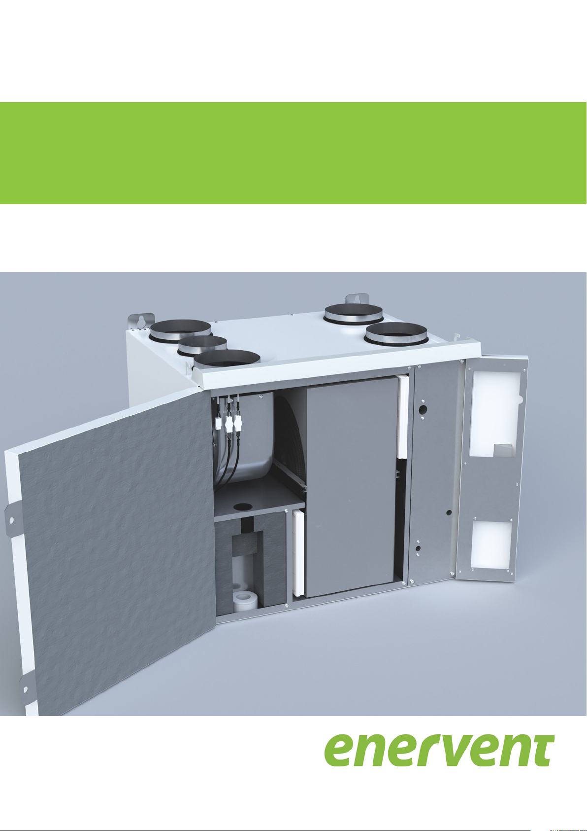
Enervent Salla eWind
Installation instructions for the ventilation unit
19 September 2018

Copyright © Enervent Zehnder Oy 2018.
Unauthorised copying and distribution is
prohibited.
2

CONTENTS
READ FIRST ................................................................................................................4
Type plate .............................................................................................................5
SAFETY ....................................................................................................................6
General information . . . . . . . . . . . . . . . . . . . . . . . . . . . . . . . . . . . . . . . . . . . . . . . . . . . . . . . . . . . . . . . . . . . . . . . . . . . . . . . . . . . . . . . . . . . . . . . . . . . . 6
Electrical safety ........................................................................................................ 6
CONTENTS OF THE DELIVERY . . . . . . . . . . . . . . . . . . . . . . . . . . . . . . . . . . . . . . . . . . . . . . . . . . . . . . . . . . . . . . . . . . . . . . . . . . . . . . . . . . . . . . . . . . . . . . 7
Available accessories . . . . . . . . . . . . . . . . . . . . . . . . . . . . . . . . . . . . . . . . . . . . . . . . . . . . . . . . . . . . . . . . . . . . . . . . . . . . . . . . . . . . . . . . . . . . . . . . . . . 7
TECHNICAL SPECIFICATIONS OF THE UNIT . . . . . . . . . . . . . . . . . . . . . . . . . . . . . . . . . . . . . . . . . . . . . . . . . . . . . . . . . . . . . . . . . . . . . . . . . . . . . . . . . 8
Duct connections . . . . . . . . . . . . . . . . . . . . . . . . . . . . . . . . . . . . . . . . . . . . . . . . . . . . . . . . . . . . . . . . . . . . . . . . . . . . . . . . . . . . . . . . . . . . . . . . . . . . . . 9
Checking the handedness in the type plate . . . . . . . . . . . . . . . . . . . . . . . . . . . . . . . . . . . . . . . . . . . . . . . . . . . . . . . . . . . . . . . . . . . . . . . . . . . . 9
BEFORE INSTALLATION . . . . . . . . . . . . . . . . . . . . . . . . . . . . . . . . . . . . . . . . . . . . . . . . . . . . . . . . . . . . . . . . . . . . . . . . . . . . . . . . . . . . . . . . . . . . . . . . . . . 10
Choosing the installation location . . . . . . . . . . . . . . . . . . . . . . . . . . . . . . . . . . . . . . . . . . . . . . . . . . . . . . . . . . . . . . . . . . . . . . . . . . . . . . . . . . . . . 10
INSTALLATION ............................................................................................................11
Wall installation without a bracket . . . . . . . . . . . . . . . . . . . . . . . . . . . . . . . . . . . . . . . . . . . . . . . . . . . . . . . . . . . . . . . . . . . . . . . . . . . . . . . . . . . . . 11
Installation of the eWind control panel . . . . . . . . . . . . . . . . . . . . . . . . . . . . . . . . . . . . . . . . . . . . . . . . . . . . . . . . . . . . . . . . . . . . . . . . . . . . . . . . 12
Installation to the Modbus bus . . . . . . . . . . . . . . . . . . . . . . . . . . . . . . . . . . . . . . . . . . . . . . . . . . . . . . . . . . . . . . . . . . . . . . . . . . . . . . . . . . . . . . . . 14
Setting the Modbus parameters to the control system . . . . . . . . . . . . . . . . . . . . . . . . . . . . . . . . . . . . . . . . . . . . . . . . . . . . . . . . . . . . . 14
COMMISSIONING .........................................................................................................15
Requirements .........................................................................................................15
Air flow adjustment . . . . . . . . . . . . . . . . . . . . . . . . . . . . . . . . . . . . . . . . . . . . . . . . . . . . . . . . . . . . . . . . . . . . . . . . . . . . . . . . . . . . . . . . . . . . . . . . . . . 15
Commissioning checklist . . . . . . . . . . . . . . . . . . . . . . . . . . . . . . . . . . . . . . . . . . . . . . . . . . . . . . . . . . . . . . . . . . . . . . . . . . . . . . . . . . . . . . . . . . . . . . 15
Control system and the eWind operation panel . . . . . . . . . . . . . . . . . . . . . . . . . . . . . . . . . . . . . . . . . . . . . . . . . . . . . . . . . . . . . . . . . . . . . . . 16
Important information about the control system. . . . . . . . . . . . . . . . . . . . . . . . . . . . . . . . . . . . . . . . . . . . . . . . . . . . . . . . . . . . . . . . . . . 16
Setting the operational parameters . . . . . . . . . . . . . . . . . . . . . . . . . . . . . . . . . . . . . . . . . . . . . . . . . . . . . . . . . . . . . . . . . . . . . . . . . . . . . . . . 16
Data display ...........................................................................................................19
eWind info list . . . . . . . . . . . . . . . . . . . . . . . . . . . . . . . . . . . . . . . . . . . . . . . . . . . . . . . . . . . . . . . . . . . . . . . . . . . . . . . . . . . . . . . . . . . . . . . . . . . . . 19
Measurement display . . . . . . . . . . . . . . . . . . . . . . . . . . . . . . . . . . . . . . . . . . . . . . . . . . . . . . . . . . . . . . . . . . . . . . . . . . . . . . . . . . . . . . . . . . . . . . . . . 20
eWind measurement list . . . . . . . . . . . . . . . . . . . . . . . . . . . . . . . . . . . . . . . . . . . . . . . . . . . . . . . . . . . . . . . . . . . . . . . . . . . . . . . . . . . . . . . . . . . 20
Commissioning documentation . . . . . . . . . . . . . . . . . . . . . . . . . . . . . . . . . . . . . . . . . . . . . . . . . . . . . . . . . . . . . . . . . . . . . . . . . . . . . . . . . . . . . . . 20
Troubleshooting ......................................................................................................21
APPENDICES ..............................................................................................................23
Dimensional drawings . . . . . . . . . . . . . . . . . . . . . . . . . . . . . . . . . . . . . . . . . . . . . . . . . . . . . . . . . . . . . . . . . . . . . . . . . . . . . . . . . . . . . . . . . . . . . . . . 23
Technical dimensional drawing, 4-duct right-handed . . . . . . . . . . . . . . . . . . . . . . . . . . . . . . . . . . . . . . . . . . . . . . . . . . . . . . . . . . . . . . 23
Technical dimensional drawing, 4-duct left-handed . . . . . . . . . . . . . . . . . . . . . . . . . . . . . . . . . . . . . . . . . . . . . . . . . . . . . . . . . . . . . . . . 24
Technical dimensional drawing, 5-duct right-handed . . . . . . . . . . . . . . . . . . . . . . . . . . . . . . . . . . . . . . . . . . . . . . . . . . . . . . . . . . . . . . 25
Technical dimensional drawing, 5-duct left-handed . . . . . . . . . . . . . . . . . . . . . . . . . . . . . . . . . . . . . . . . . . . . . . . . . . . . . . . . . . . . . . . . 26
Electrical diagrams . . . . . . . . . . . . . . . . . . . . . . . . . . . . . . . . . . . . . . . . . . . . . . . . . . . . . . . . . . . . . . . . . . . . . . . . . . . . . . . . . . . . . . . . . . . . . . . . . . . . 27
Connections ......................................................................................................27
EU declaration of conformity . . . . . . . . . . . . . . . . . . . . . . . . . . . . . . . . . . . . . . . . . . . . . . . . . . . . . . . . . . . . . . . . . . . . . . . . . . . . . . . . . . . . . . . . . . 29
QUICK REFERENCE GUIDE . . . . . . . . . . . . . . . . . . . . . . . . . . . . . . . . . . . . . . . . . . . . . . . . . . . . . . . . . . . . . . . . . . . . . . . . . . . . . . . . . . . . . . . . . . . . . . . . . 32
3Installation instructions for professionals

READ FIRST
This instruction manual is intended for all the persons
involved in the installation of the Enervent ventilation
units. Only qualified professionals may install the
equipment described in this manual in accordance with
the instructions in this manual and the local laws and
regulations. If the instructions provided in this manual are
not followed, the warranty for the equipment becomes
void and damages may be caused to persons or property.
The equipment described in this manual may not be
used by persons (including children) with reduced
physical, sensory or mental capacity or without sufficient
experience or knowledge, unless a person responsible for
their safety is supervising and advising them in the use of
the equipment.
FOR YOUR INFORMATION
If the delivery does not contain all of the
components listed in the section ‘Contents of
the delivery’, please check the order and contact
your distributor or Enervent before commencing
installation.
4
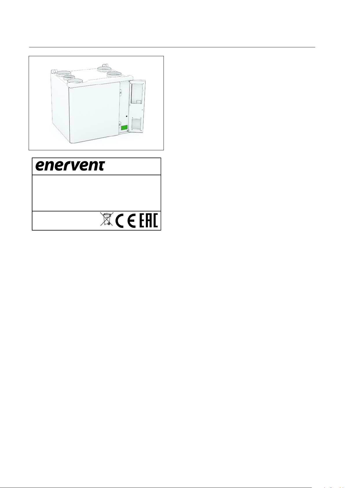
TYPE PLATE
TYYPPI/TYPE:
W/ V/ HZ / A:
SRJ. NRO/SERIAL NO:
ilmanvaihtolaite
ventilation unit
www.enervent.com
If you need technical support, please check the
equipment type and serial number from the type plate.
IP 20
5Installation instructions for professionals

SAFETY
General information
Electrical safety
DANGER DANGER
Always check that the supply voltage to the
equipment is switched off before opening the
service hatch.
WARNING
In case of a malfunction, always determine the
reason for the malfunction before restarting the
unit.
Only an authorised electrician may open the
electrical box.
DANGER
Follow the local regulations on electrical
installations.
WARNING CAUTION
When you have switched off the power to the
unit, wait for two (2) minutes before starting the
maintenance work. Even though the power is
switched off, the fans continue running and the
post-heating coil remains hot for a while.
Check that the unit is completely isolated from
the mains supply before conducting any voltage
tests, insulation resistance measurements or other
electrical work or measurements. Such work may
damage the sensitive electrical equipment.
CAUTION
Control equipment used in the ventilation units
may cause leakage current. This may affect the
operation of the residual current protection.
CAUTION
All ventilation units containing a control system
must be equipped with an overvoltage protector.
6
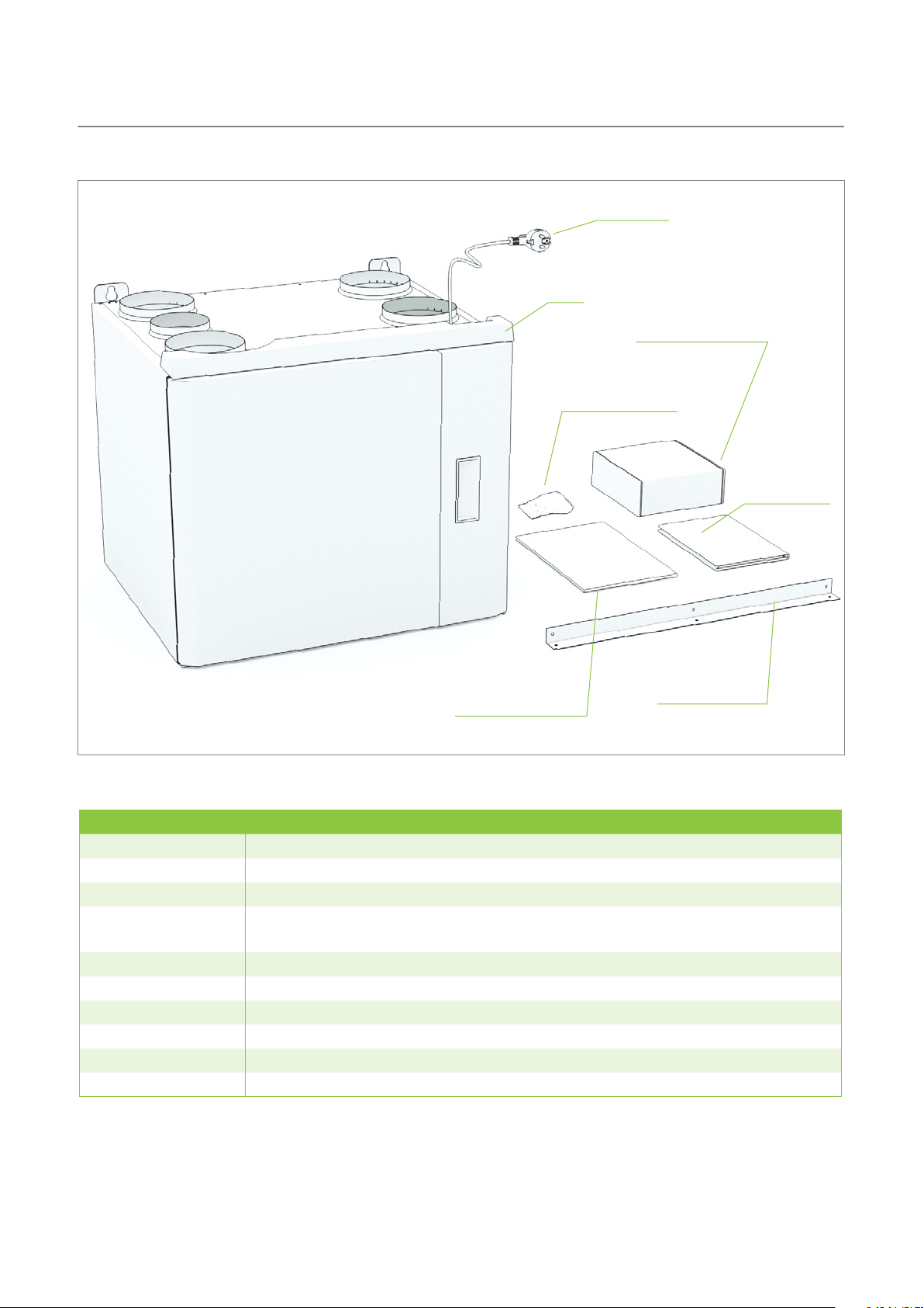
CONTENTS OF THE DELIVERY
power cable
unit
eWind control panel
vibration-damping
rubber pads
installation
and operating
instructions
warranty and
maintenance manual
installation panel
Available accessories
Product number Product name
K240130301 Range hood Standard Plus white
K240130302 Range hood Standard Plus stainless steel
K240130201 Range hood Premium white
K580040001 eWind controller. The package contains a controller, surface mounting box and a 10-metre
cable
K930030004 CO2 carbon dioxide transmitter for the room 0–10 V/24 V
K930030006 %RH humidity transmitter 0–10 V/24 V
M230110002 Humidity transmitter duct mounted KLK100
K930030008 Overpressure push button ‘fireplace switch’/boost
K930030029 KNX bus adapter
K900010010 Water trap Enervent Salla
7Installation instructions for professionals

TECHNICAL SPECIFICATIONS OF THE UNIT
Right-handed CHC
connection cable with plug
inlets for external sensors
motherboard
type plate
extract fan
extract filter
heat exchanger
inlet filter
supply fan
condensate connection G 1/4"
internal thread
Width 580 mm
Depth 500 mm
Height 490 mm
Weight 45 kg
Duct connection (duct size) Ø 160 mm
Duct connection (duct size) CHC Ø 125 mm
Range hood connection (duct size) CHC Ø 100 mm
Fans supply 118 W, 1.0 A; exhaust 118 W, 1.0 A
Heat exchanger motor with thermal protection 5 W, 0.04 A
Power of electric post-heating coil in E-models 400 W/230 V, 1~/50 Hz/1.74 A
Power of electric pre-heating coil in Arctic models 800 W/230 V, 1~/50 Hz/3.5 A
Input power, E-model (post-heating coil) 641 W/230 V, 1~/50 Hz/3.78 A
Input power E Arctic model (post-heating and pre-heating coil) 1441 W/230 V, 1~/50 Hz/7.26 A
Circuit breaker B10 A
Mains supply 230 V, 1~/50 Hz/10 A
heat exchanger’s drive belt
heat exchanger’s spare belt
8

Duct connections
supply air outdoor air
outdoor air
extract air exhaust air
right-handed 4-duct
range hood
outdoor air
extract air
exhaust air
supply air
exhaust air
supply air
left-handed 4-duct
supply air
exhaust air
extract air
range hood
outdoor air
extract air
right-handed 5-duct
left-handed 5-duct
Checking the handedness in the type plate
ilmanvaihtolaite
ventilation unit
TYYPPI/TYPE:
W/ V/ HZ / A:
SRJ. NRO/SERIAL NO:
www.enervent.com
Right-handed 4-duct
TYYPPI/TYPE:
W/ V/ HZ / A:
SRJ. NRO/SERIAL NO:
Salla eWind E RIGHT
IP 20
ilmanvaihtolaite
ventilation unit
Salla CHC eWind RIGHT
SRJ. NRO/SERIAL NO:
www.enervent.com
Left-handed 4-duct
SRJ. NRO/SERIAL NO:
TYYPPI/TYPE:
W/ V/ HZ / A:
IP 20
TYYPPI/TYPE:
W/ V/ HZ / A:
ilmanvaihtolaite
ventilation unit
Salla eWind E LEFT
ilmanvaihtolaite
ventilation unit
Salla CHC eWind LEFT
www.enervent.com
Right-handed 5-duct
IP 20
www.enervent.com
Left-handed 5-duct
IP 20
9Installation instructions for professionals

BEFORE INSTALLATION
Choosing the installation location
• Ensure that the ventilation system has been designed
and realised in accordance with the building
regulations.
• We recommend that the unit be installed in the
technical facility.
• Do not install the unit in a room where the
temperature and humidity are high. Under certain
conditions, condensation may occur on the outer
surface of the unit.
• Take the noise level of the unit into account when
choosing the installation location.
• Install the unit on a soundproof wall, if possible.
WOULD YOU LIKE TO KNOW MORE?
If you would like to know more about the
construction of ventilation systems and the
insulation of ventilation ducts, you can read about
them on our website at www.enervent.com.
• Do not install the ventilation unit directly outside
the bedroom, as the unit is never completely silent,
although it is quiet.
• Install an insulation plate behind the ventilation unit,
or try to prevent the sound from being conducted to
the structure by other means. Using soft foam sheets
is recommended (not included in the delivery).
• Ensure that connecting the condensation water
discharge pipe and water trap is possible. Remember
to take the space required by the condensation water
connection into account.
• Install the unit in a warm room (over +5°C).
• Ensure that at least 500 mm of free space is left in
front of and at least 80 mm of free space is left below
the unit for maintenance purposes.
10

FOR YOUR INFORMATION
A
B
INSTALLATION
Wall installation without
a bracket
45 kg
!
3
Check before the installation of the ventilation
unit that there are no foreign objects in the
ventilation unit or ductwork.
21
4
A = min. 25 mm, B = min. 75 mm
5
vibration-damping rubber pad
7 8
6
condensate
connection G 1/4"
internal thread
11Installation instructions for professionals

Installation of the eWind control panel
The eWind control panel (see section ‘Control system and the eWind operation panel’ on page 16) is installed in a wallmounted device box or using the surface-mounting box supplied with the accessory delivery. No more than two external
control panels can be installed in the ventilation unit.
1 2
3
5
4
6
12
7
8
OP1

9
11
10
13Installation instructions for professionals

Installation to the Modbus bus
The ventilation unit can also be controlled via the Modbus
connector X26.
Modbus specification:
• Modbus address 1 (default)
• Data transmission protocol RS485
• Modbus traffic via the motherboard’s Modbus
connector X26
• Speed 9,600, 19,200 or 115,200 bps
• 8-bit
• No parity or parity
The order of the poles in the Freeway connector is marked
in the controller board.
The Modbus registers are available on the Enervent
website at www.enervent.com.
CAUTION
Do not connect an external bus to the
motherboard before the bus has been
programmed and is compatible with the control
of the unit.
X26
Setting the Modbus parameters to the
control system
1
Simultaneously press the buttons
three times in the control panel.
2
Using buttons
c31-c32. • The meaning of each parameter is described in
section ‘Parameter list’ on page 16.
Select the parameter to be adjusted by pressing
3
button for 3 seconds.
4
Change the parameter value using buttons
and .
5
Confirm the value by pressing button
Exit the settings by simultaneously pressing
6
buttons
and , choose the parameters
and .
and
.
14

COMMISSIONING
Requirements
Operational requirements for the ventilation unit:
• Supply and exhaust air temperature below +55°C.
• Exhaust air temperature at least +10°C
• Supply air temperature for heat recovery over +5°C
• Supply air temperature over +10°C
• All foreign objects have been removed from the
ventilation system
• Both fans are running
Air flow adjustment
When the unit has been switched on, the air flows must
be adjusted to the designed values.
• The air flows are adjusted in connection with the
commissioning of the ventilation unit.
• The adjustment is made separately for both fans in
each operation mode (= at each fan speed).
Check the following during the adjustment:
• All filters are clean.
• All supply and extract air vents, the roof inlet, and the
outdoor air grilles are in place.
FOR YOUR INFORMATION
Do not cover the outdoor air grille with a
mosquito net.
To achieve optimum adjustment values, the air flows
must be measured at each duct opening. A suitable
measurement device is a thermoanemometer or
a differential pressure gauge. With the aid of the
measurement values, the air flow can be adjusted to
match the design values.
A correctly adjusted ventilation unit is quiet and provides
a good thermal economy. In addition, it also maintains
a slight negative pressure in the house. The negative
pressure prevents humidity from entering the walls and
ceiling.
Commissioning checklist
Measure Inspected Notes
The unit has been installed in accordance with the installation
instructions provided by the manufacturer.
The condensation water discharge pipe has been connected to
the water trap, and its operation has been tested.
Silencers have been installed in the supply and extract air ducts.
The terminal devices have been connected to the ductwork.
An outdoor air grille has been installed for the intake of fresh air.
NOTE: Do not cover the grille with a mosquito net. It makes
cleaning difficult.
The unit has been connected to an appropriate power supply.
The ventilation ducts have been insulated in accordance with the
ventilation plan.
The airflows are adjusted according to the ventilation plan.
15Installation instructions for professionals

Control system and the eWind operation panel
1
4
2
3
1. Mode (standard display) 2. Temperature (standard display) 3. Mode button
4. Eco button 5. Temperature button 6. Cable connection
Important information about the control
5
6
Setting the operational parameters
system
The fan speed settings for different operation modes must
The factory settings are suitable for most installations.
The fan speed settings for various operating modes are
installation specific, and they must be specified and set
separately in connection with each installation. In other
cases, the factory setting must not be changed unless
otherwise instructed in the ventilation system plan.
Make sure that all necessary information is available before
starting to adjust the settings.
be specified and set separately in connection with each
installation. The settings are described in the parameter
table.
1
Simultaneously press buttons
times.
2
Using buttons
c1-c32. • The meaning of each parameter is described in
section ‘Parameter list’ on page 16.
Select the parameter to be adjusted by pressing
3
button for 3 seconds.
and , choose the parameters
and three
16
4
Change the parameter value using buttons
and .
Confirm the value and return to the selection of
5
parameters c1–c32 by pressing button
Exit the settings by simultaneously pressing
6
buttons
and .
.

Parameter list
Parameter Description
c1 Extract fan speed, mode 1, region: 20–100%,
step: 1%
c2 Supply fan speed, mode 1, control range:
20–100%, step: 1%
c3 Extract fan speed, mode 2, control range:
20–100%, step: 1%
c4 Supply fan speed, mode 2, control range:
20–100%, step: 1%
c5 Extract fan speed, mode 3, control range:
20–100%, step: 1%
c6 Supply fan speed, mode 3, control range:
20–100%, step: 1%
c7 Extract fan speed, mode 4, control range:
20–100%, step: 1%
c8 Supply fan speed, mode 4, control range:
20–100%, step: 1%
c9 Time limit for manual boosting (mode 4),
control range: 0–4 h, step: 1 h
c10 Extract fan speed, fireplace/range hood
mode, control range: 20–100%, step: 1%
Factory
setting
36% ‘Away’ mode 102
35% ‘Away’ mode 100
56% Home mode 52
55% Home mode 51
83% Maximum power also in the removal of
80% Maximum power also in the removal of
100% Manual boosting 68
100% Manual boosting 67
2 h Setting the time limit 0 h prevents
30% 55
Note
humidity and carbon dioxide
humidity and carbon dioxide
the use of mode 4 and activates the
3-speed external control
Modbus
register
74
72
66
Field
setting
c11 Supply fan speed, fireplace/range hood
mode, control range: 20–100%, step: 1%
c12 Time limit for fireplace mode/selection of
range hood, control range: 0–15 min, step:
1 min
c13 Heat recovery defrosting, on/off Off Coil 55
c14 Maintenance reminder interval 4 or 6
months
c15 CHG/AGH pre-heating and AGH precooling,
on/off
c16 CHG/AGH outdoor temperature TE01, below
which pre-heating is used, control range:
0–10°C, step 1°C (for pre-heating)
c17 CHG/AGH pre-heating is not in use when the
outdoor air temperature (TE01) rises above
value (c16) + (c17), control range: 1–5°C, step
1°C
c18 CG cooling or CHG pre-cooling, on/off On Applies to CG and CHG heat
c19 Outdoor temperature TE01, above which
pre-cooling/cooling is allowed
c20 AGH outdoor temperature, above which the
earth duct is used, control range: 15–25°C,
step 1°C, (for pre-cooling)
50% 54
10 min Setting time limit 0 min replaces the
replace mode with the range hood
mode.
4 Register value in days 538
On Coil 58
5°C 592
1°C 593
exchangers
17°C 164
20°C 629
56
Coil 52
c21 AGH pre-cooling is not in use when the
outdoor air temperature (TE01) drops below
value (c20-c21), control range: 1–5°C, step
1°C
c22 Temperature setting for air temperature
after the electric pre-heating, control range:
–10...–20°C, step: 1°C
c23 Boosted operation for the removal of
humidity, on/off
2°C 630
–15°C 591
On Coil 19
17Installation instructions for professionals

Parameter list
Parameter Description
c24 Threshold value for summer/winter
Factory
setting
4°C
temperature,
control range –10…+10°C, step 1°C
c25 Threshold value for dehumidification,
45%
control range 10–100 %RH, step 5%
c26 Threshold value for starting
15%
dehumidification, control range: 5–30%,
humidity exceeds the 48-hour average value,
step 5%
c27 Boosted operation for the removal of carbon
Off Coil 21
dioxide, on/off
c28 Threshold value for starting the carbon
dioxide removal, control range: 600–1,200
1,000
ppm
ppm, step: 100 ppm
c29 Boosted operation for the removal of
Off Coil 24
humidity with the rotating heat exchanger,
on/off
c30 Display dimmed in the standby mode, on/off Off
c31 Modbus address of the automation
1 640
motherboard, control range: 1–99, step: 1
c32 Modbus bus speed, 1 = 9,600, 2 = 19,200, 3
2 19,200 bps 733
= 115,200
Note
The 24-hour average temperature of the
outdoor air. Above the threshold value, the
boosted operation for the removal humidity
is in the summer mode, and below the
threshold value, it is in the winter mode.
In the winter mode, the boosted operation
for the removal of humidity starts when the
humidity value exceeds the threshold value.
In the summer mode, the boosted operation
of for the removal of humidity starts when
the relative humidity exceeds the 48-hour
average value of humidity by the amount of
the threshold value.
Panel-specific setting off: dark display in the
standby mode, on: dimmed display in the
standby mode.
Modbus
register
137
69
70
76
Internal
Field
setting
18

Data display
You can view the available functions in the eWind info list on the data display.
eWind info list
Opening:
1
Simultaneously press buttons
Parameter (n1..nn) is displayed.
2
Browse the info list using buttons
and once. •
and .
Return to the standard view:
3
Simultaneously press buttons
and once.
FOR YOUR INFORMATION
If you do not press any button, the menu will
close in 5 minutes and the panel will return to the
standard view.
eWind info list
Marking Denition
n0 Standard mode is on
n1 Boosted ventilation for the removal of
humidity
n2 Boosted ventilation for the removal of carbon
dioxide
n3 Heat recovery is on
n4 Post-heating with an electric or water coil is
on
n5 Outdoor air pre-heating with CHG/AGH or an
electric pre-heater is on
n6 Supply air CG, CHG, or AGH cooling is on
n7 Cold recovery with the rotating heat
exchanger is on
n8 Ventilation boosted manually
n9 Away mode is on
n10 Dehumidification with rotor is on
n11 Defrosting is on
n12 Eco mode is on
n13 Maintenance reminder: the time remaining
until the next filter replacement in days
n14 Unit is starting
19Installation instructions for professionals

Measurement display
You can monitor temperature, humidity, heat recovery
efficiency and other measurement values in the eWind
measurement list, which is displayed on the measurement
display.
eWind measurement list
Opening:
1
Simultaneously press buttons
times. • Parameter (r1..rn) and the parameter values are
displayed.
2 Browse the parameter list up or down by pressing
button or .
Return to the standard view:
and two
1
Simultaneously press buttons
eWind measurement list
Marking in the chart
Marking Denition
r1 Outdoor air temperature, °C TE01 All models 6
r2 Supply air temperature after heat
recovery, °C
r3 Supply air temperature, °C TE10 All models 8
r4 Exhaust air temperature, °C TE30 All models 10
r5 Extract air temperature, °C TE32 All models 9
r6 Return water temperature of water-based
heating coil, °C
r7 Temperature of pre-heated outdoor air
(CHG/AGH/electric pre-heater), °C
r8 Relative humidity (RH) of exhaust air RH30 All models 13
r9 Carbon monoxide level, ppm Without an external carbon
r10 Measurement of external relative
humidity, %RH
r11 Temperature efficiency of the supply air
heat recovery, %
r12 Temperature efficiency of the exhaust air
heat recovery, %
and the connection
in the automation
motherboard
TE05 All models 7
TE45 eWind W only. Other models
TE02 Only if equipped with CHG/AGH
Note
display ‘0’.
or an electric pre-heater.
dioxide sensor (accessory), ‘- -’ is
displayed
Without an external humidity
sensor (accessory), ‘- -’ is
displayed-
All models Calculated value 29
All models Calculated value 30
and once.
Modbus
register
12
32
23
23
Commissioning documentation
• Fill in the warranty information.
• Mark the changes you have made to the factory
settings in the column Field setting in the table
‘Parameter list’ on page 16.
• Fill in the air volume measurement document.
20
FOR YOUR INFORMATION
The warranty is not valid for units with no
documented air volume measurement.
It is extremely important to record all the changes
made to the parameters. This ensures that there
are backup copies of the information in case the
automation is damaged (e.g., by a lightning strike).

Troubleshooting
Alarm Description
FILS Maintenance
reminder.
Err Sensor
malfunction
- - - - Downloading. The eWind panel is downloading
oFFE Stop mode. The ventilation
AL1 The water-
heating coil is
in danger of
freezing.
AL2 The supply
air is cold
after the
rotating heat
exchanger.
AL3 Cold supply
air.
Alarm
limit
4 or 6
months
+8°C Cold supply air. The water coil is frozen/about to
+5°C Cold supply air. The heat exchanger does not
+10°C Cold supply air. The extract fan has stopped. Replace the fan.
Symptoms Possible cause Measure Notes
It is time for the periodic
maintenance.
The sensor has short-circuited,
or there is an interruption in the
circuit.
data from the motherboard.
is off.
The external control system has
switched the ventilation unit to
stop mode.
freeze:
• The circulation pump has
stopped.
• The heat exchanger does not
rotate.
• The control valve actuator of
the water coil is faulty.
• The extract fan has stopped.
rotate:
• The drive belt is damaged.
• The drive belt skids.
• The heat exchanger motor is
damaged.
The extract filter is clogged. Replace the filter.
The ventilation has been
adjusted incorrectly/not been
adjusted at all.
The heat insulation of the ducts is
insufficient.
The fan speed of the ventilation
unit is incorrect.
Replace the filters.
Inspect the ventilation unit.
Clean, if necessary.
Check the unit for visible
damages.
Check the connections and
cables of the sensors.
Normal in connection
with start-up. In other
situations, check the eWind
connection cable.
Restart the pump.
Replace the motor or the
belt.
Replace the actuator.
Identify the cause/replace
the fan.
Replace the drive belt.
Clean or replace the belt
and the heat exchanger.
Replace the heat exchanger
motor.
Adjust the ventilation
in accordance with
the ventilation system
plan using appropriate
measurement tools.
Check the insulation
thickness of the supply and
exhaust air ducts and add
insulation, if necessary.
Always use a fan speed
specified by the ventilation
unit designer (also in the
winter).
Acknowledge by
pressing any button
for 5 seconds.
The unit will not
start until the alarm
mode has been
cleared and the
alarm has been
reset by pressing
a button in the
operation panel.
The ventilation
unit switches to
malfunction mode,
in which the fans
run at minimum
power.
The alarm is
automatically reset
when the fault is
cleared.
21Installation instructions for professionals

Alarm Description
AL4 Supply fan
malfunction.
AL5 Extract fan
malfunction.
AL6 Cold exhaust
air.
Alarm
limit
+10°C Cold supply air. Low indoor temperature. Raise the indoor
Symptoms Possible cause Measure Notes
No supply air. The supply fan has stopped. Repair or replace the supply
No exhaust air. The extract fan has stopped. Repair or replace the extract
Insufficient heat insulation of the
exhaust air duct.
The ventilation unit’s service
hatch is open.
Temperature sensor TE30 is
faulty.
fan.
fan.
temperature.
Check the insulation of the
ducts and add insulation, if
necessary.
Close the service hatch.
Repair or replace the sensor.
The unit will not
start until the alarm
mode has been
cleared and the
alarm has been
reset by pressing
a button in the
operation panel.
The ventilation
unit switches to
malfunction mode,
in which the fans
run at minimum
power.
The alarm is
automatically reset
when the fault is
cleared.
AL7 Hot supply
air.
Fire hazard.
AL8 Overheating
of the electric
post-heater
or pre-heater.
AL9 Hot exhaust
air. Fire
hazard.
+55°C Hot supply air. Fire hazard. Check for heat sources. The unit will not
There is a malfunction in the
electric post-heater.
There is a malfunction in the
actuator of the water-based postheater’s valve.
Temperature sensor TE10 is
faulty.
Hot supply air. Electric pre-heater or post-heater
does not work:
• Overheating protector has
tripped.
• The supply fan has stopped.
• The supply air filter is clogged.
• The outdoor air grille is
clogged.
• The heater’s controller board is
damaged.
• The heater is damaged.
+55°C Overheating. Fire hazard. Temperature sensor
TE30 is faulty.
Repair or replace the electric
post-heater.
Repair or replace the valve’s
actuator.
Repair or replace the
temperature sensor.
Identify the cause
for overheating and
acknowledge the error
message.
Identify the cause/replace
the fan.
Replace the filter.
Clean the grille.
Remove the possible
mosquito net.
Replace the controller
board.
Replace the heater.
Check for heat sources.
Repair or replace the
temperature sensor.
start until the alarm
mode has been
cleared and the
ventilation unit has
been restarted.
22

APPENDICES
Dimensional drawings
Technical dimensional drawing, 4-duct right-handed
23Installation instructions for professionals

Technical dimensional drawing, 4-duct left-handed
24

Technical dimensional drawing, 5-duct right-handed
25Installation instructions for professionals

Technical dimensional drawing, 5-duct left-handed
26

Electrical diagrams
Connections
Abbreviation
Colour:
BK BLACK
BN BROWN
RD RED
OG ORANGE
YE YELLOW
GN GREEN
BU BLUE
GY GREY
WH WHITE
27Installation instructions for professionals

Marking on the circuit
board
AI1
DO8
OP1
28
FIREPLACE/RANGE HOOD MODE DI6
AWAY AWAY MODE DI5
Name Denition
FP/EX
BOOST MANUAL BOOSTING DI4
ESTOP EMERGENCY STOP DI1
RETURN WATER TEMPERATURE SENSOR eWind W MODELS TE45
TE45
RETURN WATER TEMPERATURE SENSOR eWind CG MODELS TE45
TE46
PRE-HEATED OUTDOOR AIR TEMPERATURE, EXTERNAL PRE-HEATER TE02
TE02
RETURN AIR TEMPERATURE ((KOTILÄMPÖ eWind) TE02
TE20
TE10 SUPPLY AIR TEMPERATURE TE10
OUTDOOR AIR TEMPERATURE TE01
EXTERNAL HUMIDITY SENSOR AS DEFAULT (RH 0–100%). IF PARAMETER c27 IS ACTIVE, CO₂
SENSOR (200–2,000 ppm) (ACCESSORY)
PRE-HEATING ACTUATOR, CHG MODELS. COOLING ACTUATOR, CG MODELS AO6
HEATING ACTUATOR, W MODELS AO5
PRE-HEATER MODELS COOLING ON/OFF CONTROL, CG MODELS, CONDENSATE TRAY
HEATER
TE01
RH CO₂
TL01
TL50
TL45
DO8 ALARM OUTPUT A AS DEFAULT PRE-HEATING ON/OFF CONTROL, CHG –AGH, ELECTRIC
DO5 OUTDOOR AIR AND EXTRACT AIR DAMPER CONTROL (ACCESSORY) DO5
CONTROL PANEL HAS NOT BEEN INSTALLED IN THE VENTILATION UNIT
DO2 HEATING ON/OFF CONTROL eWind MODELS MAX 500-W PUMP DO2
OP1 CONTROL PANEL (1) INCLUDED IN THE DELIVERY, 10-M CABLE ALSO INCLUDED IF THE
OP2 CONTROL PANEL (ACCESSORY), 10-M CABLE INCLUDED IN THE DELIVERY OP2

EU DECLARATION OF CONFORMITY
We declare that our products follows the provisions of low voltage directive LVD 2014/35/EU, electromagnetic
compatibility directive EMC 2014/30/EU, machine directive MD 2006/42/EC, radio equipment directive RED
2014/53/EU, ROHS II directive 2011/65/EU, battery directive 2013/56/EU and waste electrical and electronic
equipment directive WEEE 2012/19/EU.
Manufacturer: Enervent Zehnder Oy
Manufacturer´s contact: Kipinätie 1, 06150 Porvoo, FINLAND,
enervent@enervent.com, www.enervent.com
Description of the product: Ventilation unit with heat recovery
Trade name of the product:
Salla eWind E CHC left, Salla eWind E (D) right, Salla eWind E (D) left,
Salla eWind E CHC (D) right, Salla eWind E CHC (D) left
The products are in conformity with the following standards:
LVD EN 60335-1:2012/A11:2014
EMC EN 61000-3-2:2014 and EN 61000-3-3:2013
EN 61000-6-1:2007 and EN 61000-6-3:2007/A1:2011/AC:2012
RED EN 300328 v2.1.1
MD EN ISO 12100:2010
ROHS EN 50581:2012
The conformity of each manufactured product is taken care according our quality descriptions.
Product is CE-marked year 2018.
Porvoo 3rd of September 2018
Enervent Oy
Tom Palmgren
Technology manager
tel. +358 207 528 800, fax +358 207 528 844
Salla eWind E right, Salla eWind E left, Salla eWind E CHC right,
EN 62233:2008/AC:2008
EN 55014-1:2006/A2:2011 and EN 55014-2:1997/A2:2008
29Installation instructions for professionals

30

31Installation instructions for professionals

Quick reference guide for the installer
<˚C
>˚C
>˚C
>˚C
<˚C
<˚C
˚C
version xx.xx.xx
x 3
> 3 sec
Parameters (c)
c1 36%
c2
c3
c4
c5
c6
c7
c8
c9
c10
c11
c12 10 min
(20–100%)
35%
(20–100%)
56%
(20–100%)
55%
(20–100%)
83%
(20–100%)
80%
(20–100%)
100% (20–100%)
(120 min)
100% (20–100%)
(120 min)
2 h
(1...4 h)
30%
(20–100%)
50%
(20–100%)
(5...15 min)
Parameters (c)
c13 oFF
c14
c15
c16
c17
c18
c19
c20
c21
c22
(on/oFF)
4
(4/6)
oFF
(on/oFF)
=> on,
TE01 < °C,
5°C (0…10°C)
=> off, TE01 >
(c16 + c17),
1°C (1…5°C)
on
on/oFF
=> on,
TE01 > °C, 17°C
=> on,
TE01 > °C,
20°C (15…25°C)
=> off, TE01 <
(c20 - c21),
2°C (1…5°C)
–15°C
(-10…-20°C)
Parameters (c)
c23
%RH
c24
c25
c26
c27
c28
c29
c30
c31 eWind
c32 Modbus 2
%RH
%RH
%CO
2
%CO
2
%RH
Modbus
%RH
48 h
on
(on/oFF)
4°C
(–10…+10°C)
45%
(10...100%RH)
=>on, 48 h %RH
+ c26,
15% (5…30%)
oFF
(on/oFF)
CO2=> on,
1,000 ppm
(600...1,200)
oFF
(on/oFF)
oFF
(on/oFF)
1
(1...99)
(1 = 9600, 2
= 19200, 3 =
115200)
x 2
%RH
˚C
˚C
RH30
%CO
%RH
2
η%
˚C
TE30
˚C
TE10
η%
TE32
TE01
˚C
TE02
Enervent Zehnder Oy
Kipinätie 1
FI-06150 Porvoo, Finland
Tel. +358 207 528 800
Fax +358 207 528 844
enervent@enervent.com
www.enervent.com
TE05
˚C
 Loading...