

Page 1
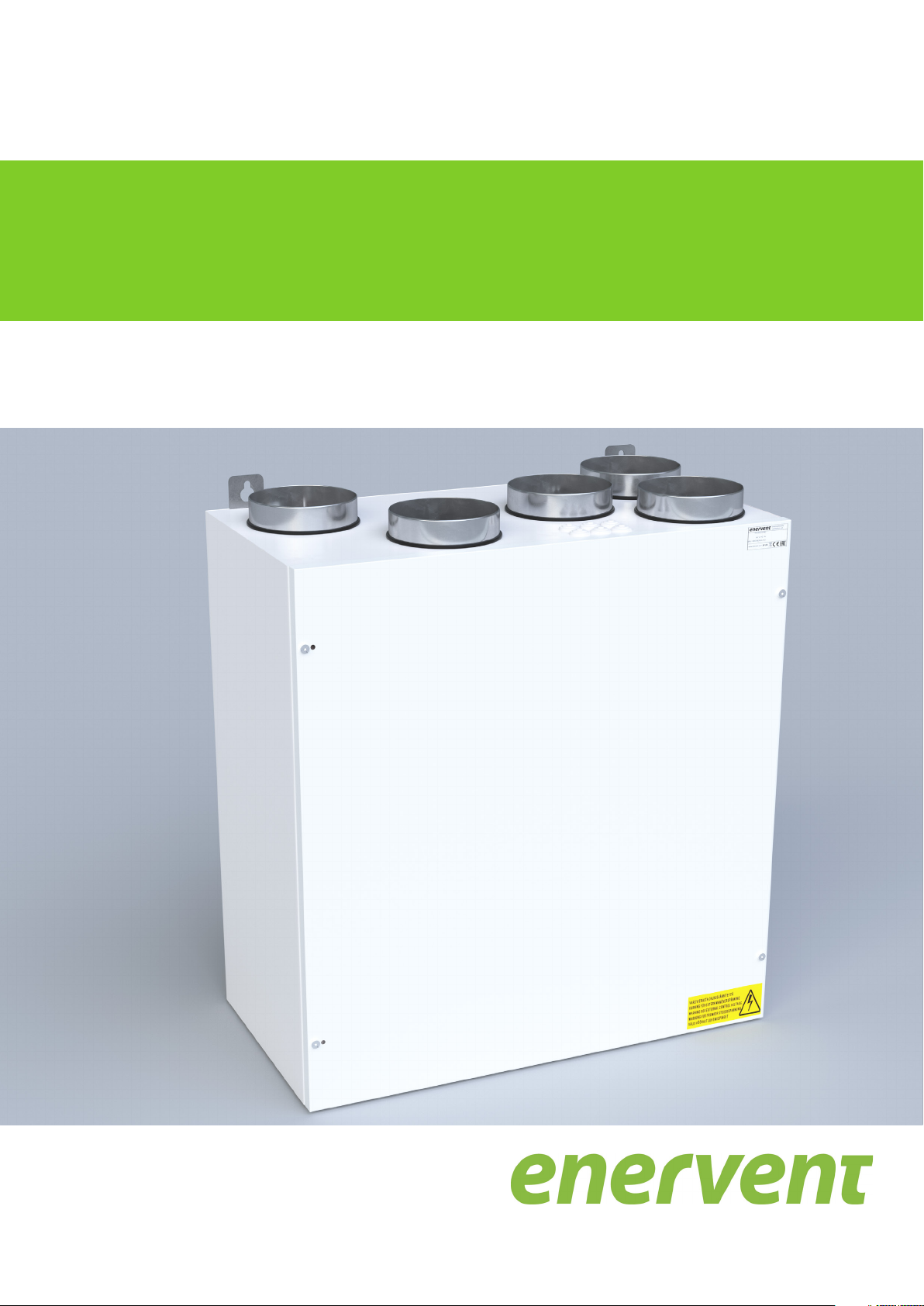
Enervent Pinion
Ventilation unit operation and maintenance instructions
19 October 2017
Page 2

Copyright © Enervent 2017.
Unauthorised copying and distribution is forbidden.
2
Page 3

Contents
READ FIRST ................................................................................................................ 4
PURPOSE OF USE .......................................................................................................... 4
SAFETY .................................................................................................................... 5
General ................................................................................................................ 5
Electrical safety ........................................................................................................ 5
TYPE PLATE ................................................................................................................ 5
USE OF THE VENTILATION UNIT . . . . . . . . . . . . . . . . . . . . . . . . . . . . . . . . . . . . . . . . . . . . . . . . . . . . . . . . . . . . . . . . . . . . . . . . . . . . . . . . . . . . . . . . . . . . 6
Daily use of the ventilation . . . . . . . . . . . . . . . . . . . . . . . . . . . . . . . . . . . . . . . . . . . . . . . . . . . . . . . . . . . . . . . . . . . . . . . . . . . . . . . . . . . . . . . . . . . . . 6
Operation modes . . . . . . . . . . . . . . . . . . . . . . . . . . . . . . . . . . . . . . . . . . . . . . . . . . . . . . . . . . . . . . . . . . . . . . . . . . . . . . . . . . . . . . . . . . . . . . . . . . . . . . 6
Away mode (1) . . . . . . . . . . . . . . . . . . . . . . . . . . . . . . . . . . . . . . . . . . . . . . . . . . . . . . . . . . . . . . . . . . . . . . . . . . . . . . . . . . . . . . . . . . . . . . . . . . . . . 7
Home mode (2) . . . . . . . . . . . . . . . . . . . . . . . . . . . . . . . . . . . . . . . . . . . . . . . . . . . . . . . . . . . . . . . . . . . . . . . . . . . . . . . . . . . . . . . . . . . . . . . . . . . . 7
Home mode, boosted ventilation (3) . . . . . . . . . . . . . . . . . . . . . . . . . . . . . . . . . . . . . . . . . . . . . . . . . . . . . . . . . . . . . . . . . . . . . . . . . . . . . . . 7
Boosted mode (4) . . . . . . . . . . . . . . . . . . . . . . . . . . . . . . . . . . . . . . . . . . . . . . . . . . . . . . . . . . . . . . . . . . . . . . . . . . . . . . . . . . . . . . . . . . . . . . . . . . 7
To change the supply air temperature . . . . . . . . . . . . . . . . . . . . . . . . . . . . . . . . . . . . . . . . . . . . . . . . . . . . . . . . . . . . . . . . . . . . . . . . . . . . . . 7
Hood mode ........................................................................................................ 8
Heating mode . . . . . . . . . . . . . . . . . . . . . . . . . . . . . . . . . . . . . . . . . . . . . . . . . . . . . . . . . . . . . . . . . . . . . . . . . . . . . . . . . . . . . . . . . . . . . . . . . . . . . . 8
Eco mode .......................................................................................................... 8
EFFICIENT USE OF THE VENTILATION . . . . . . . . . . . . . . . . . . . . . . . . . . . . . . . . . . . . . . . . . . . . . . . . . . . . . . . . . . . . . . . . . . . . . . . . . . . . . . . . . . . . . . . 9
Use of the ventilation during the cold season . . . . . . . . . . . . . . . . . . . . . . . . . . . . . . . . . . . . . . . . . . . . . . . . . . . . . . . . . . . . . . . . . . . . . . . . . . 9
ADDITIONAL FUNCTIONS . . . . . . . . . . . . . . . . . . . . . . . . . . . . . . . . . . . . . . . . . . . . . . . . . . . . . . . . . . . . . . . . . . . . . . . . . . . . . . . . . . . . . . . . . . . . . . . . . 10
Service reminder display . . . . . . . . . . . . . . . . . . . . . . . . . . . . . . . . . . . . . . . . . . . . . . . . . . . . . . . . . . . . . . . . . . . . . . . . . . . . . . . . . . . . . . . . . . . . . . 10
Time for next service . . . . . . . . . . . . . . . . . . . . . . . . . . . . . . . . . . . . . . . . . . . . . . . . . . . . . . . . . . . . . . . . . . . . . . . . . . . . . . . . . . . . . . . . . . . . . . 10
Set-up display .........................................................................................................10
ADJUSTMENTS ...........................................................................................................10
Supply air is too warm . . . . . . . . . . . . . . . . . . . . . . . . . . . . . . . . . . . . . . . . . . . . . . . . . . . . . . . . . . . . . . . . . . . . . . . . . . . . . . . . . . . . . . . . . . . . . . . . 10
Supply air is too cold . . . . . . . . . . . . . . . . . . . . . . . . . . . . . . . . . . . . . . . . . . . . . . . . . . . . . . . . . . . . . . . . . . . . . . . . . . . . . . . . . . . . . . . . . . . . . . . . . . 10
Ventilation is noisy . . . . . . . . . . . . . . . . . . . . . . . . . . . . . . . . . . . . . . . . . . . . . . . . . . . . . . . . . . . . . . . . . . . . . . . . . . . . . . . . . . . . . . . . . . . . . . . . . . . . 11
Indoor air is too humid . . . . . . . . . . . . . . . . . . . . . . . . . . . . . . . . . . . . . . . . . . . . . . . . . . . . . . . . . . . . . . . . . . . . . . . . . . . . . . . . . . . . . . . . . . . . . . . 11
Ventilation does not work . . . . . . . . . . . . . . . . . . . . . . . . . . . . . . . . . . . . . . . . . . . . . . . . . . . . . . . . . . . . . . . . . . . . . . . . . . . . . . . . . . . . . . . . . . . . . 11
MAINTENANCE ...........................................................................................................12
Service reminder ......................................................................................................12
Filters .................................................................................................................12
Replacing filters, left-handed model . . . . . . . . . . . . . . . . . . . . . . . . . . . . . . . . . . . . . . . . . . . . . . . . . . . . . . . . . . . . . . . . . . . . . . . . . . . . . . . 13
Replacing filters, right-handed model . . . . . . . . . . . . . . . . . . . . . . . . . . . . . . . . . . . . . . . . . . . . . . . . . . . . . . . . . . . . . . . . . . . . . . . . . . . . . . 14
ADDING WATER TO THE WATER TRAP (REMOVAL OF THE CONDENSATION WATER) 15
Left-handed model . . . . . . . . . . . . . . . . . . . . . . . . . . . . . . . . . . . . . . . . . . . . . . . . . . . . . . . . . . . . . . . . . . . . . . . . . . . . . . . . . . . . . . . . . . . . . . . . 15
Right-handed model . . . . . . . . . . . . . . . . . . . . . . . . . . . . . . . . . . . . . . . . . . . . . . . . . . . . . . . . . . . . . . . . . . . . . . . . . . . . . . . . . . . . . . . . . . . . . . 15
TROUBLESHOOTING ......................................................................................................16
USER’S QUICK GUIDE . . . . . . . . . . . . . . . . . . . . . . . . . . . . . . . . . . . . . . . . . . . . . . . . . . . . . . . . . . . . . . . . . . . . . . . . . . . . . . . . . . . . . . . . . . . . . . . . . . . . . 20
3Ventilation unit operation and maintenance instructions
Page 4

READ FIRST
PURPOSE OF USE
This instruction manual is intended for all users of the
Enervent ventilation units. Only qualified persons may
install the equipment described in this manual, according
to the manufacturer’s instructions and the local laws
and regulations. Unless the instructions provided in this
manual are followed, the warranty for the equipment
becomes void and personal and material damages may
be result.
The equipment described in this manual may not be
used by persons (including children) with reduced
physical, sensory or mental capacity or without sufficient
experience or knowledge, unless a person responsible for
their safety is supervising and counselling in the use of the
equipment.
The purpose of the unit is to improve the quality of indoor
air and its primary function is ventilation.
The unit is also used for the recovery of heat energy from
the extract air. In addition, depending on the model and
accessories the unit can be used for cooling the supply air
in summer. It can also be used for regulating the moisture
and carbon dioxide levels of indoor air.
4
Page 5
SAFETY
General
DANGER
Always check before opening the service hatch
that the supply voltage of the equipment is
switched off.
WARNING
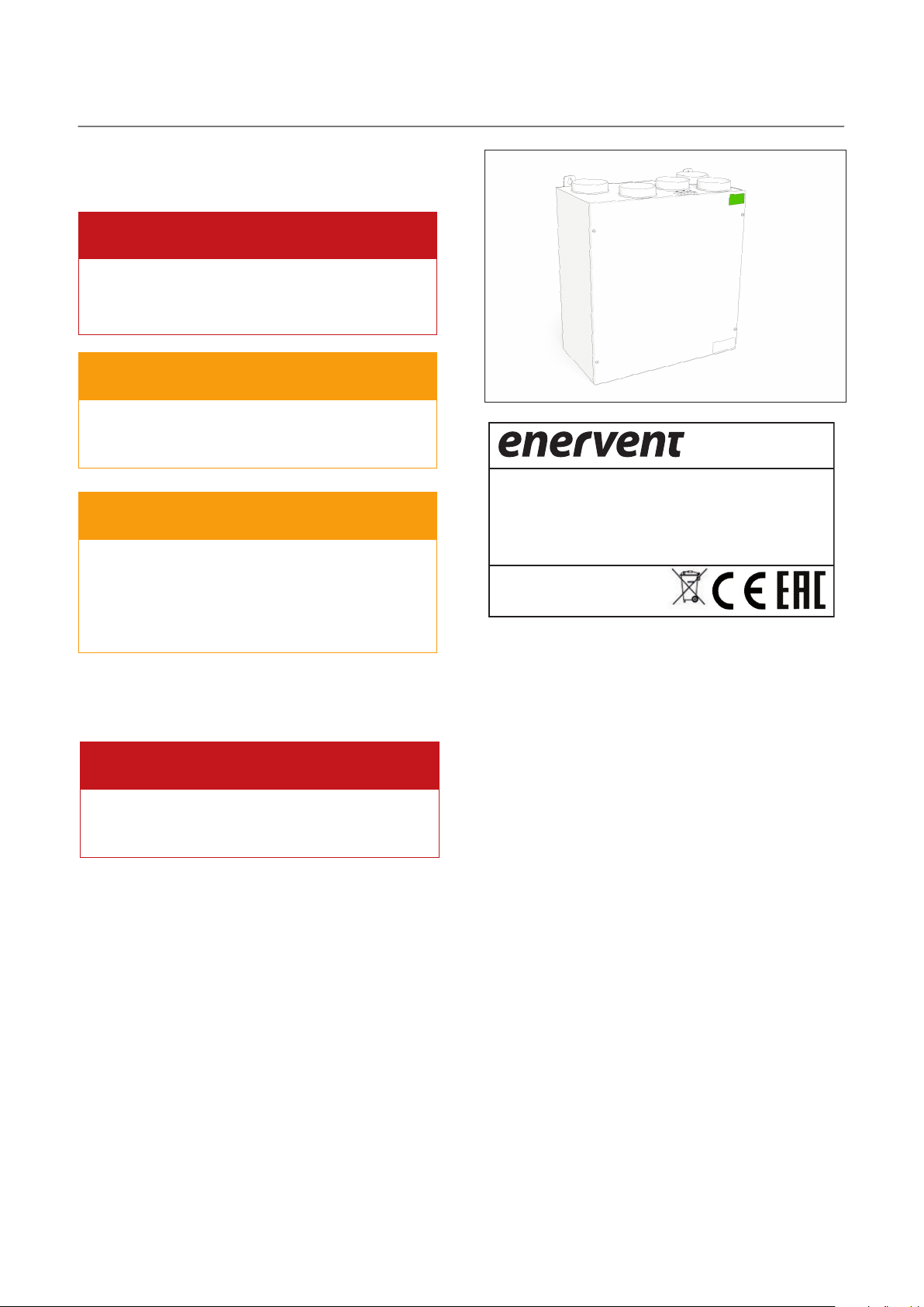
TYPE PLATE
In case of malfunction, always find out the reason
for the malfunction before starting the unit again.
WARNING
Wait for two (2) minutes after switching off the
unit power before you commence with the
maintenance. Although the power is switched off,
the fans continue running and the after-heating
coil stays hot for a while.
Electrical safety
DANGER
Only an authorised electrician may perform any
actions in the electrical box.
ilmanvaihtolaite
ventilation unit
TYYPPI/TYPE:
W/ V/ HZ / A:
SRJ. NRO/SERIAL NO:
www.enervent.com
Should you need any technical support, refer to the
equipment type and serial number in the type plate.
IP 20
5Ventilation unit operation and maintenance instructions
Page 6

USE OF THE VENTILATION UNIT
When the ventilation system has been carefully
designed and installed, any actions from the users are
seldom needed. The user can just relax and enjoy good
ventilation.
1
2
3
4
5
Button/display Description
Mode display Current operation mode
Temperature display Target temperature of the
supply air
Mode button Selection of the operation
mode (browsing of the
parameters)
Eco button Selection of Eco mode
(browsing of the parameters)
Temperature button Selection of the target
temperature of the supply air
NOTE:
Some functions of the control panel are for
installation or maintenance purposes only.
The eWind control panel
The eWind control panel
1. Mode (in basic view) 2. Temperature (in basic view) 3. Mode button
4. Eco button 5. Temperature button
Daily use of the ventilation
The ventilation is adjusted with an easy-to-use control
panel, the operation of which is based on actual situations
of use. Operation modes based on these situations cover
all the ventilation needs of your home. When you change
the operation mode, the operation of the ventilation unit
is changed accordingly. The installer of the unit adjusts
the settings for each operation mode when installing the
ventilation unit.
The control panel is usually in standby mode where the
display is dimmed. You can activate the panel by pressing
any button.
Operation modes
1 = Away (when you are not at home)
2 = Home (when you are at home)
3 = Home (when you are at home, boosted ventilation)
4 = Boosted (when the ventilation needs to be boosted
more)
F-PL = Fireplace mode (when lighting a fire in the
fireplace)
HEAt = Heating on/heating off
Eco = Energy-saving ventilation
PdC = Hood mode
6
Page 7

Away mode (1)
You can reduce ventilation when you are going to be
away for an extended period of time, e.g., due to a trip.
To select:
1
Go to mode 1 by pressing button .
• The ventilation system will enter the selected mode.
NOTE:
You can select Away mode by using an external
switch as well (if installed).
Home mode (2)
When you are at home, the ventilation unit functions
normally in Home mode.
To select:
1
Go to mode 2 by pressing button .
• The ventilation system will enter the selected mode.
Home mode, boosted ventilation (3)
NOTE:
If Boosted mode is controlled by pressing an
external button, the mode will remain on as long
as the button is activated. When the button is
released, Boosted mode will remain on for the
duration set in the system. The factory setting is 2
hours.
To change the supply air temperature
The target temperature of the supply air (displayed on the
screen) is set when installing the system. You can adjust
the temperature on the scale 15...22 °C. To adjust:
1 Go to the desired target temperature by pressing
button .
• The system adjusts the efficiency of the heat recovery
or the effect of the after-heating/cooling accordingly.
Fireplace mode
The Fireplace mode may be useful when you light a fire in
the fireplace.
To select:
When you need more efficient ventilation, you can
increase the airflow.
To select:
1
Go to mode 3 by pressing button .
• The ventilation system will enter the selected mode.
Boosted mode (4)
When you have visitors, the ventilation level of the mode
designed for everyday use may not be sufficient. This may
be the case, for example, when several people are having
a sauna.
To select:
1
Go to mode 4 by pressing button .
• The ventilation system will enter the selected mode.
There is a time limit in Boosted mode. The passing of
time is displayed on the screen by alternating bars
after the number of the mode.
WARNING
Fireplace mode is designed for use only when
lighting a fire in the fireplace – not to be used as
the source of replacement air when using the
fireplace.
TIP
Unnecessary use of Fireplace mode causes
unnecessary waste of energy.
1
Press button for 3 seconds. Text on will be
displayed for a short period of time and then
followed by F-PL.
7Ventilation unit operation and maintenance instructions
Page 8

To go back to Home mode:
1
Press button for 3 seconds. The text oFF will
be displayed for a short period of time. Next, the
display will return to the basic view.
NOTE:
The heater does not heat the supply air when the
outside temperature exceeds +25 °C.
NOTE:
The default duration of Fireplace mode is 10
minutes and you can select it at most two times
per day. When the time has elapsed, the system
will return to the previous mode.
You can select Fireplace mode by using a separate
Fireplace button as well (if installed).
If a cooker hood has been connected to the unit,
the fireplace mode will not be available.
Hood mode
In Hood mode, the unit will boost ventilation and remove
cooking smells from the cooker more efficiently. When
the cooker hood has been connected to the unit and the
hood boosting has been activated from the hood, the text
"PdC" will be displayed on the screen. When this mode is
selected, the unit’s mode cannot be changed by using the
eWind control panel.
Heating mode
In Heating mode the supply air is heated by using the
integrated heater. To select:
1
Press button for 3 seconds. The text HEAt will
be displayed for a short period of time. Next, the
display will return to the standard view.
Eco mode
When you select Eco mode in the ventilation system, the
system will save energy by making minor adjustments
in the set temperature and airflow values. In Eco mode,
the system does not react to changes in temperature as
quickly as in the normal mode. It will first examine which
way the temperature is going before it starts to heat or
cool the supply air.
This green operation mode will not significantly reduce
comfort, but it will reduce costs.
To select:
1
Press button . The text ECO and on will be
displayed for a short period of time. Next, the
display will return to the basic view. The ventilation
system will enter the selected mode.
To go back to Home mode:
1
Press button . The texts ECO and oFF will be
displayed for a short period of time. Next, the
display will return to the basic view.
NOTE:
The selected Eco mode will be switched off when
the outside temperature exceeds +25 °C and
it will be switched back on when the outside
temperature falls below +25 °C.
To go back to Home mode:
1
Press button for 3 seconds. The texts HEAt and
oFF will be displayed for a short period of time.
Next, the display will return to the standard view.
8
Page 9

EFFICIENT USE OF THE VENTILATION
A correctly designed and used ventilation system reduces
costs and saves energy. In addition, it promotes the health
of both the living environment and the residents.
• Always use the ventilation system according to the
plan drawn up for your home – around the year.
• Clean or replace the filters when the system advises
you to do so and vacuum-clean the interior of the unit
regularly.
• Open the lid of the ventilation unit and take a look
inside the unit regularly, e.g. once a month.
• Dust or other impurities in the air may accumulate
in the equipment. Dirt blocks the filters and adheres
to the heat exchanger and weakens the efficiency of
ventilation.
• Use special modes, such as Fireplace mode, only
when necessary.
• The unnecessary use of special modes increases
energy consumption.
• Instead of or in addition to adjusting the ventilation
system, you can improve living comfort by using
traditional methods:
• Keep the curtains and windows closed on hot days
in order to keep out the heat of the sun. Dress more
warmly on cold days. This will help you to save a lot of
energy.
• Use only spare parts approved by Enervent.
• Use original filters only. They have been designed
to ensure the best possible performance of your
ventilation system.
• Use Eco mode in order to save energy and reduce
costs, without compromising the quality of indoor air.
Use of the ventilation during
the cold season
CAUTION
Reducing ventilation may cause serious damage
to the structures of your house.
Do not reduce ventilation or switch it off when the
outdoor temperature drops. Instead of decreasing, the
costs may increase. Your ventilation system is the result
of a professional system designer. Changes in the outside
temperature have been taken into consideration in
designing the system and the unit. If there are no changes
in your daily routines, no adjustments are required in the
ventilation system.
If you reduce airflow in cold weather, ice may form inside
the ventilation unit. The risk is especially high in extremely
cold weather and when the indoor air humidity is high
(the shower is used frequently and large amounts of
laundry are dried).
If the structure of the ventilation system needs to be
updated, contact the designer of the system.
9Ventilation unit operation and maintenance instructions
Page 10

ADDITIONAL FUNCTIONS ADJUSTMENTS
Service reminder display
The purpose of the service reminder is to remind the user
when the service interval has elapsed. The maintenance
interval is 4 or 6 months depending on the model.
When the service interval has elapsed, the text FILS will
be displayed on the screen.
Time for next service
Checking:
1
Simultaneously press buttons and once.
Browse to the parameter n13 by pressing button
2
• The time remaining until the next service is displayed
.
in days.
Set-up display
Supply air is too warm
If the air coming from the ventilation system is too warm:
Go to a lower supply air target temperature by
1.
pressing button . The temperature value on
the panel will change and the ventilation system
will be adjusted according to the set target
temperature.
NOTE:
The system uses all of its devices in order to reach
the required temperature. Missing devices, such
as a cooling coil, may cause a higher temperature
than the one you selected.
Using Eco mode maximises heat recovery in
warmer weather as well. However, it may also
cause the supply air to be too warm. In this case,
switch off Eco mode.
The set-up display is designed for professional use only. It
displays the current settings in the ventilation system and
enables changing the settings.
CAUTION
Changing the settings is only allowed for an
authorised person who has received sufficient
training in using the ventilation system.
Supply air is too cold
If the air coming from the ventilation system is too cold:
Go to a higher supply air target temperature by pressing
the button. The temperature value on the panel
will change and the ventilation system will be adjusted
according to the set target temperature.
NOTE:
The system uses all of its devices in order to
reach the required temperature. Missing devices,
such as an after-heating coil, may cause a lower
temperature than the one you selected.
Insufficient maintenance: Cold supply air can be
caused by, for example, a blocked filter or the heat
recovery’s worn-out drive belt.
10
See also the following section: Heating mode, on
page 8
Page 11

Ventilation is not sufficient
Indoor air is too humid
If the ventilation is not sufficient:
1. Check that the filters are clean and that they do not
need to be replaced.
• If the filters are dirty, replace them according to the
instructions provided in the section "Filters" on page
12.
2. Check that no changes have occurred in the need
for ventilation after the design and installation of the
system.
• If changes have occurred in the number of people
living in your household or in your routines, the
ventilation system may need to be updated. Contact
the designer of your ventilation system.
Ventilation is noisy
Although our ventilation units are fairly quiet, they are
never totally silent. If the ventilation system has been
designed and installed correctly (no devices are placed
close to the bedroom and soundproof doors and silencers
are used), disturbance caused by ventilation can be
reduced to a minimum.
If the ventilation is unusually noisy:
1. Check that the filters are clean and that they do not
need to be replaced.
2. If the filters are dirty, replace them according to the
instructions provided in the section "Filters" on page
12.
3. Check that the fans are clean and that they do not
require cleaning.
4. If the fans are dirty, clean them as instructed in the
maintenance instructions.
5. Check that the automated humidity boosting for
removing moisture is not on.
6. Open the Information display and browse to the
parameter n1. If the parameter is visible, the humidity
boosting is on.
In addition to feeling the humidity, you may also identify
a too high moisture content by listening to the sound
caused by the ventilation. If the automatic humidity
boosting is always on, the humidity may be too high and
thus the ventilation system is trying to return the humidity
to the correct level.
If the indoor air is too humid:
1. Check that the filters are clean and that they do not
need to be replaced.
• If the filters are dirty, replace them according to the
instructions provided in the section "Filters" on page
12.
2. Check that no changes have occurred in the need
for ventilation after the design and installation of the
system.
NOTE:
If changes have occurred in the number of people
living in your household and/or using the shower
or sauna, the ventilation system may need to be
updated. Contact the designer of your ventilation
system.
Ventilation does not work
If the ventilation does not work:
1. Check that the unit is connected to the electricity
supply.
2. Check that the fuse has not tripped in the electricity
distribution board.
If all these matters are ok and the ventilation still does not
work, contact maintenance.
NOTE:
If the automatic humidity boosting is always
on, the humidity may be too high. Contact the
designer of your ventilation system.
11Ventilation unit operation and maintenance instructions
Page 12

MAINTENANCE
The unit requires very little maintenance. The required
maintenance usually includes the following tasks:
• replacing the filters
• cleaning the heat exchanger (in connection with
cleaning the ventilation ducts)
• cleaning the fans (in connection with cleaning the
ventilation ducts)
• checking the condensation water discharge pipe.
DANGER
Before commencing with maintenance, switch the
power supply off by removing the plug from the
socket outlet. Wait for two (2) minutes before you
commence the maintenance. Although the power
supply of the unit has been switched off, the fans
continue running and the electric heater will be
hot for a while.
The equipment includes moving parts (e.g., fans and the
motor and belt of the rotating heat exchanger) which
wear out in use. Due to normal wear these parts must
be replaced during the life span of the equipment. The
normal service life of the wearing parts is determined
by the operational conditions and time of use and thus
no normal maintenance interval can be specified for the
wearing parts.
Filters
Left-handed unit in the picture.
supply
filter F7
extract filter M5
M5 and F7 cassette filters are used in the ventilation unit.
The maximum recommended maintenance interval of the
cassette filter is 4 months.
Cassette filters can be cleaned by using compressed air
which extends the maintenance interval at the maximum
to six (6) months.
Service reminder
The control panel will advise the user to conduct the
regular maintenance. The service reminder FILS appears
on the control panel display when the end of the
maintenance interval has been reached.
Acknowledge the service reminder by pressing any key on
the eWind panel for 5 seconds.
FOR YOUR INFORMATION
In connection with conducting maintenance on
any part of the equipment, always check the wear
and cleanliness of other parts as well.
Watch the maintenance instruction video in our
Help Center on our website at www.enervent.
com.
FOR YOUR INFORMATION
The compressed air used must be dry and oil-free.
12
Page 13

Replacing filters, left-handed model
1
SRJ. NRO/SERIAL NO:
www.enervent.com
2 3
HEX 4
TYYPPI/TYPE:
W/ V/ HZ / A:
!
ilmanvaihtolaite
ventilation unit
PINION EWIND E LEFT
IP 20
11 kg
4 5
F7 M5
13Ventilation unit operation and maintenance instructions
Page 14

Replacing filters, right-handed model
1
SRJ. NRO/SERIAL NO:
www.enervent.com
2 3
HEX 4
TYYPPI/TYPE:
W/ V/ HZ / A:
!
ilmanvaihtolaite
ventilation unit
PINION EWIND E RIGHT
IP 20
11 kg
4 5
F7
M5
14
Page 15

ADDING WATER TO THE WATER TRAP (REMOVAL OF THE CONDENSATION WATER)
Left-handed model
Right-handed model
15Ventilation unit operation and maintenance instructions
Page 16

TROUBLESHOOTING
Alarm Description
FILS Service
reminder.
AL2 The supply
air is cold
after the
rotating heat
exchanger.
Alarm
limit
4 or 6
months
+5 °C Cold supply air. The heat exchanger does not
Symptoms Possible cause Measure Notes
It is time for regular
maintenance.
rotate:
• The drive belt is damaged.
• The drive belt skids.
• The heat exchanger motor is
damaged.
Replace the filters.
Inspect the ventilation unit.
Clean as necessary.
See if there are any damages visible.
If the drive belt is damaged,
take the spare belt into use
and clean the outer surface
of the heat exchanger. Have
the new belt and the motor
of the heat exchanger
replaced by a maintenance
company authorised by the
manufacturer.
Acknowledge by
pressing any button
for 5 seconds.
The ventilation
unit switches to
malfunction mode
and the fans operate with minimum
power.
The alarm is automatically reset
when the fault is
cleared.
Other fault codes (Err, ----, oFFE, AL1, AL3, AL4, AL5, AL6, AL7, AL8): Please contact an authorised maintenance company (refer to
https://www.enervent.com/contact-information/?_ga=2.164480572.2024853575.1507015364-2052970745.1506576827)
16
Page 17

17Ventilation unit operation and maintenance instructions
Page 18

18
Page 19

19Ventilation unit operation and maintenance instructions
Page 20

> 3 sec
User’s quick guide
version 19.10.17
˚C
Acknowledge the FILS service
reminder by pressing any key on the
eWind control panel for 5 seconds.
120 min
Press the Mode button for 3 seconds.
The text “on” will be displayed for
a short period of time and then
followed by “F-PL”.
F-PL will not be in use if a cooker
hood is connected to the equipment.
ECO
Enervent Oy
Kipinätie 1
FIN-06150 Porvoo, Finland
Tel. +358 207 528 800
Fax. +358 207 528 844
enervent@enervent.com
www.enervent.com
 Loading...