

Page 1

Ventilation unit with heat recovery
Planning, installation and operational instructions manual
Before installing and operating this unit,
please read this manual thorougly, and retain it for future reference.
www.enervent.
PICCOLO
Enervent Piccolo
Page 2

2
TABLE OF CONTENTS
TABLE OF CONTENTS
OVERVIEW
TYPE MARKING 3
TYPE DESCRIPTION 3
FOREWORD 4
WARNING 4
OPERATING PRINCIPLE 4
DUCT HEAT INSULATION 5
KITCHEN VENTILATION 5
INSTALLATION
EQUIPMENT 5
INSTALLATION 6
DRAINING THE VENTILATION UNIT 10
USER GUIDE
STARTING THE UNIT 11
ABOUT VENTILATION 11
SUPPLY AND EXTRACT AIR CALIBRATION 12
USING AND CONTROLLING THE UNIT 13
HEAT RECOVERY DEFROSTING FUNCTION 14
MAINTENANCE
MAINTENANCE 15
BELT REPLACMENT 16
TROUBLE SHOOTING 17
TECHNICAL INFORMATION
TECHNICAL INFORMATION 17
HEAT RECOVERY EFFICIENCY RATE 18
DIMENSION DRAWINGS 19
CHARACTERISTIC CURVES 26
SOUND DATA 27
CONTROL CHART 30
WIRING DIAGRAMS 31
DECLARATION OF CONFORMITY 34
QUICK GUIDE TO THE VENTILATION UNIT AND COOKER HOOD
Copyright Enervent 2011. All rights reserved.
Page 3
3
Enervent® Piccolo EN 2011_1
OVERVIEW
TYPE MARKING
Inside the ventilation unit is a type shield. Fill in the type shields data here to have it easily available when it is needed, e.g.
when buying new lters.
This manual covers the following units:
Enervent Piccolo eco ECE-ON
Enervent Piccolo eco ECE-OFF
Enervent Liggolo eco ECE
ilmastointilaite
ventilation unit
TYYPPI/TYPE:
SRJ.NRO/SERIAL NO:
W/ V/ HZ / A:
ENERVENT OY AB
KIPINÄTIE 1 06150 PORVOO
TEL +358 (0)207 528800 FAX +358 (0) 207 528844
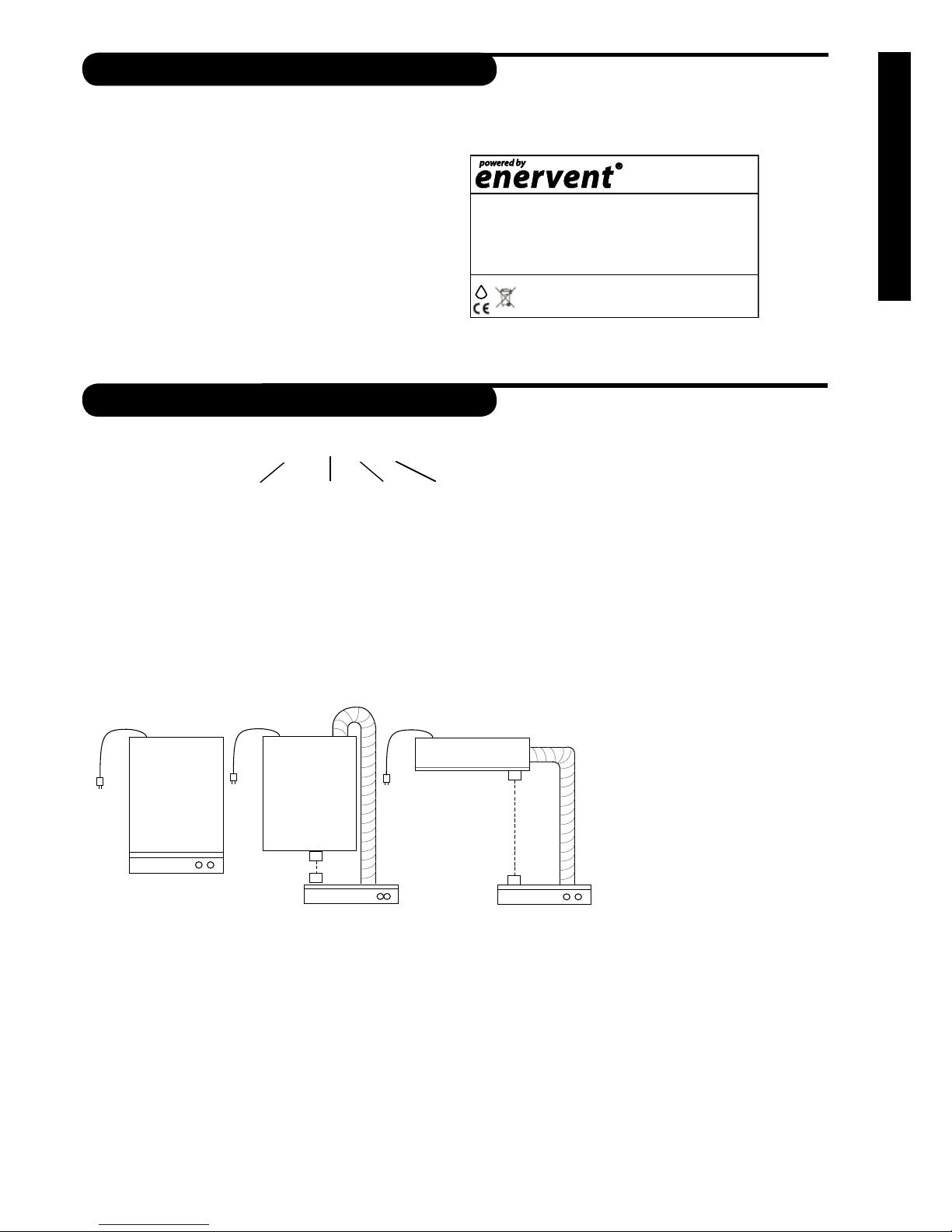
TYPE DESCRIPTION
P
P
Piccolo
ON-models
The unit is on the wall.
The cooker hood is mounted
on the ventilation unit.
Piccolo
OFF-models
Cable 8 x 1.5 mm²
The unit is on the wall.
The cooker hood and the unit are
connected with a duct.
Unit mounted hanging from the ceiling.
The cooker hood and the unit are
connected with a duct.
Liggolo
P
Cable 8 x 1.5 mm²
P
Ener vent Piccolo eco ECE-ON
Unit frame Alternating
current fans
Control
Piccolo The unit is mounted on the wall.
Liggolo A lying version of Piccolo.
eco Ventilation unit with direct current fans.
ECE Ventilation unit with ECC05 control and 800 W electrical after heater.
ON The cooker hood is mounted directly on the unit.
OFF The unit and cooker hood are connected with a duct and can hence even be installed in separate
spaces.
Installation alternative
Page 4
4
OVERVIEW
FOREWORD
All Enervent ventilation units are designed and manufactured for use all year round. In Finland the ventilation units have
been installed in houses and other spaces for over 20 years and their popularity is increasing each year. Because of the
knowledge and experience we have amassed during the years we can now manufacture more energy ecient and user
friendly ventilation units. The Enervent gr unit series is the result of a long product development. All unitsin the series are
very versatile and exible.
A unit with basic functions can be installed, by your self, with the help of this manual, but certain special functions and the
extra equipment should be connected by an electrician. We recommend that the installation is performed by a qualied
ventilation engineer.
WARNING
After opening the maintenance hatch wait two (2) minutes before starting the maintenance
work! The fans rotate for a while even after the power is cut and the ECE-model electical heatercan be searing hot. There are no user-serviceable parts inside the control panel or inside the
electrical cabinet, leave the service of these parts to a professional. It is important during troubleshooting not to turn on the power to the unit before being assured as to what the problem is.
OPERATING PRINCIPLE
The ventilation units are based on regenerative heat recovery. This is achieved with a rotating heat exchanger through
which incoming air and exhaust air ow in opposite directions. Aluminium foils within the heat exchanger transfer heat
from the exhaust air to the supply air. A characteristic of the regenerative heat exchanger is its high rate of heat recovery
(or eciency).
Enervent Piccolo and Liggolo units are linked with a cooker hood. The cooker hood is linked to the unit either directly or
with a duct. The air from the cooker hood is, with the help of the extract air fan, lead past the heat exchanger directly into
the exhaust air.
The eciency varies from 75 % to 85 %, depending on the proportion of supply air and exhaust air (the heat from the
supply air fan is taken into account). Thanks to their high eciency, the units save heating energy at the same time as they
provide excellent indoor air quality; therefore they pay themselves back in a relatively short time.
Page 5
5
Enervent® Piccolo EN 2011_1
INSTALLATION
KITCHEN VENTILATION
The general ventilation in the kitchen is taken care of with a extract air vent in the ceiling.
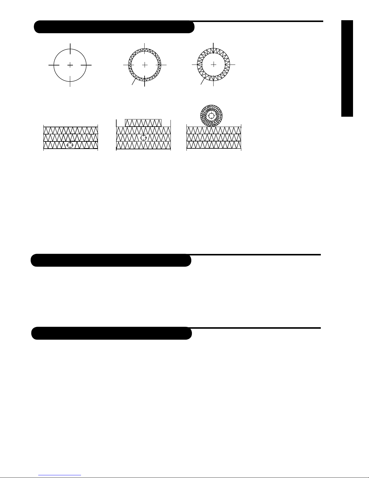
DUCT HEAT INSULATION
Examples of dierent insulation alternatives:
1. Exhaust air duct in warm spacing (indoors, no insulation).
2. Supply air duct between ventilation unit and terminal equipment.
3. Waste air and outside air duct in warm spacing (indoors).
4. Exhaust air duct in the ceiling insulation.
5. All ducts in a cold attic. Outside air and waste air ducts must not be assembled directly above the steam
barrier. Both ducts require an insulation layer of 100 mm thick mineral wool.
1.
2.
isolation 20 mm
vapour proof surface
4.
5.
isolation
100 mm
3.
isolation 80 mm
vapour proof surface
EQUIPMENT
The Enervent Piccolo (eco) ECE unit delivery includes:
1. Enervent Piccolo (eco) ECE ventilation unit
2. Attachment brackets for kitchen cabinet integration laminate
3. Standard cooker hood
The Enervent Liggolo (eco) ECE unit delivery includes:
1. Enervent Liggolo (eco) ECE ventilation unit
2. Standard cooker hood
Page 6
6
INSTALLATION
PICCOLO-MODELS:
Piccolo must be installed in a warm space (over +5°C) like a utility room or a laundry but not a garage (separate re area).
The unit can also be installed in the kitchen if the cooker hood is fastened in the unit.
If the unit is used to ventilate an area with a swimming pool, the unit must be drained. There is a drain outlet in the bottom of the unit (1/4” inner thread). At the time of delivery, the outlet is plugged.
PHASES OF INSTALLATION:
N.B.! To reduce the weight of the unit you can remove the heat recovery wheel before mounting the unit.
1. Mark and cut the holes into the ceiling.
2. Draw the ducts through the holes to the required height. The gaps between duct and steam barrier are then
sealed, with for instance ventilation tape.
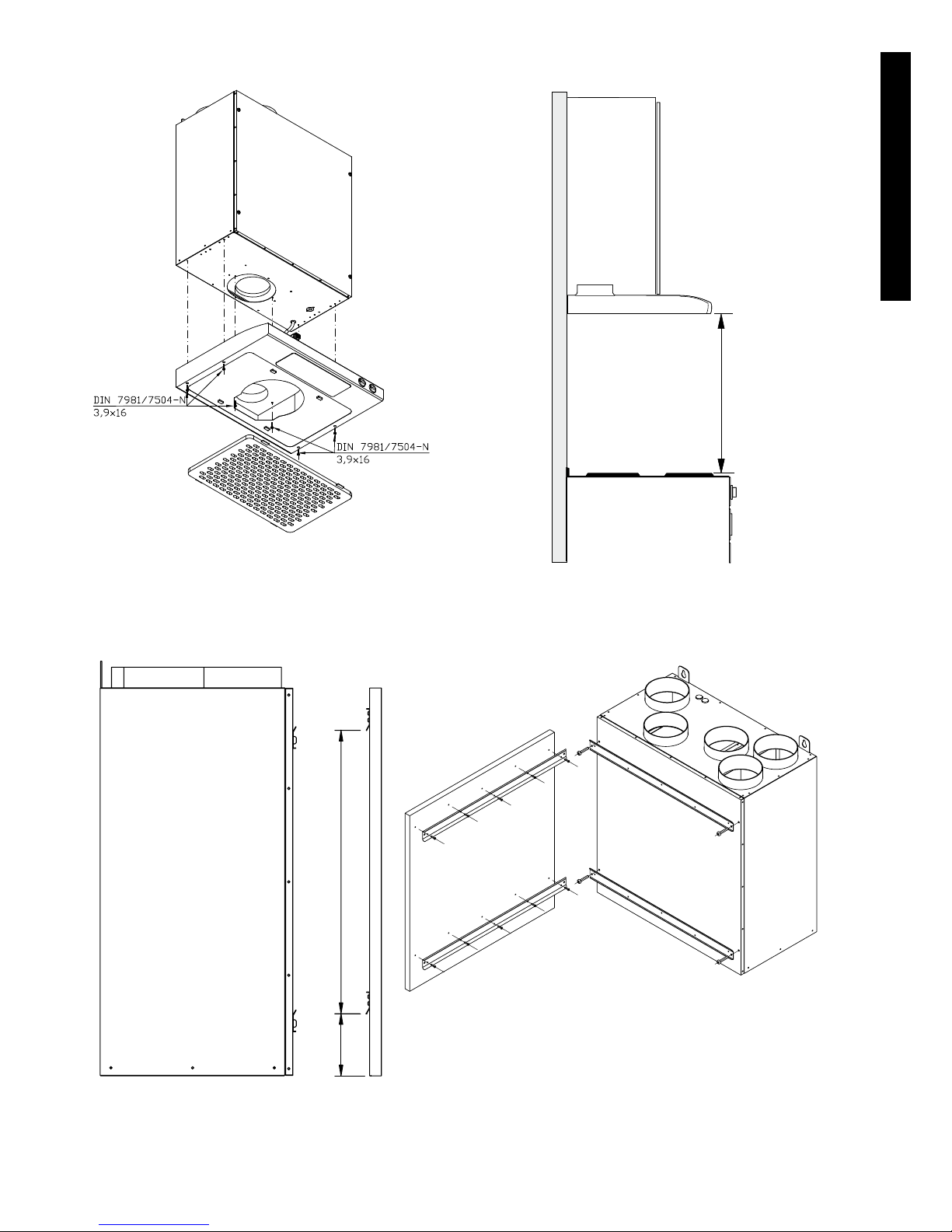
3. Attach two suspension screws at an appropriate hight at a distance of 500 mm from each other. The unit has two
suspension ears. Make sure the wall material can bear the units weight. NOTE! If the cooker hood is directly at tached to the unit, the distance between the grease lter and the stove must be at least 500 mm*.
4. Lift the unit onto the wall and thighten the screws.
5. Connect the ducts to the tubes on top of the unit. It is recommended that silencers be installed to the extract
air and supply air ducts.
6. If the unit’s condensation drain is to be used, connect a pipe between the drain outlet and the nearest oor
drain or water trap of a sink. Connecting the unit directly into the sewage system is not allowed.
* NOTE! Make sure the distance satisfys the stove manufacturers and local authorities demands.
LiGGOLO-MODELS:
Liggolo must be installed in a warm space (over +5°C) like a utility room or a laundry but not a garage (separate re area).
If the unit is used to ventilate an area with a swimming pool, the unit must be drained. There is a drain outlet in the bottom of the unit (1/4” inner thread). At the time of delivery, the outlet is plugged.
PHASES OF INSTALLATION:
N.B.! To reduce the weight of the unit you can remove the heat recovery wheel before mounting the unit.
1. Mark and cut the holes into the ceiling.
2. Draw the ducts through the holes to the required height. The gaps between duct and steam barrier are then
sealed, with for instance ventilation tape.
3. Attach suspension screws at an appropriate place in the ceiling. The unit has four suspension ears. Make sure the
ceiling material can bear the units weight.
4. Lift up the unit to the ceiling and thighten the screws.
5. Connect the ducts to the tubes on top of the unit. It is recommended that silencers be installed to the extract
air and supply air ducts.
6. If the unit’s condensation drain is to be used, connect a pipe between the drain outlet and the nearest oor
drain or water trap of a sink. Connecting the unit directly into the sewage system is not allowed.
THE COOKER HOOD
Removal of the exhaust air from the cooker hood shall be done in accordance
to logal regulations. The exhaust air must not be lead into smoke canals that
are used as exhaust of cobustion gases from gas/wood stoves, wood/oil
burners.
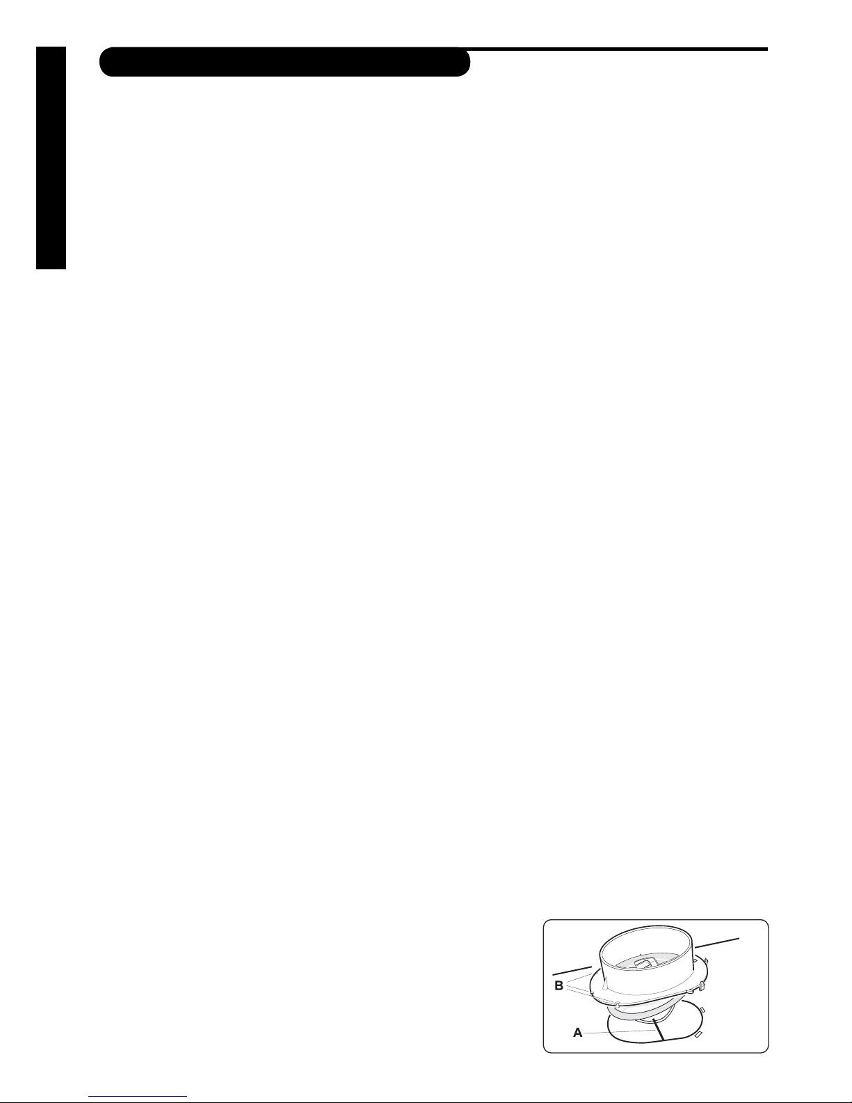
Mounting the connection cu with damper:
The connection cu is inside the cooker hood when delivered.
The damper shaft A is put in the loop beneathe the damper lid, g 1.
Make sure the clutches get beneath the sheet metal edge.
The cu will snap in place.
INSTALLATION
1
Page 7
7
Enervent® Piccolo EN 2011_1
INSTALLATION
NOTE WHEN YOU INSTALL PICCOLO ON-MODELS:
500/650
101
460.25
Mounting the cabinet integration laminate:
Page 8
8
INSTALLATION
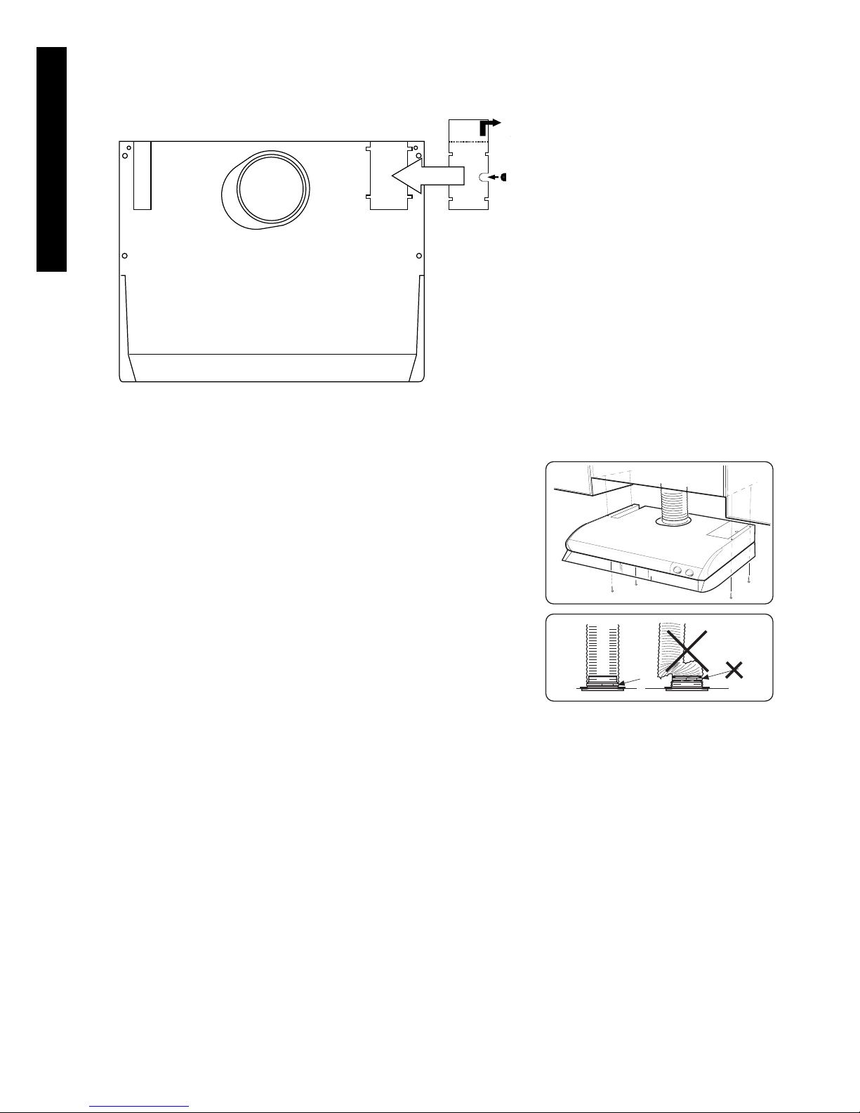
NOTE WHEN YOU INSTALL PICCOLO OFF-MODELS:
Some preparations need to be done on the cooker hood if it is not mounted on the unit.
90°
1.
2.
3.
1. Place the rubber lead through in the gap.
2. Bend the cover plate 90° along the perfora tion.
3. Place the cover plate on the hole in the
cooker hood and fasten it with the screws.
2
3
Installing the cooker hood
The cooker hood can be placed under the cup boards or embeded, g
2. Connect the cooker hood with a Ø 125 mm duct or hose. NOTE! When
using a hose, it must be installed straightened closest to the connection,
g 3.
Page 9
9
Enervent® Piccolo EN 2011_1
INSTALLATION
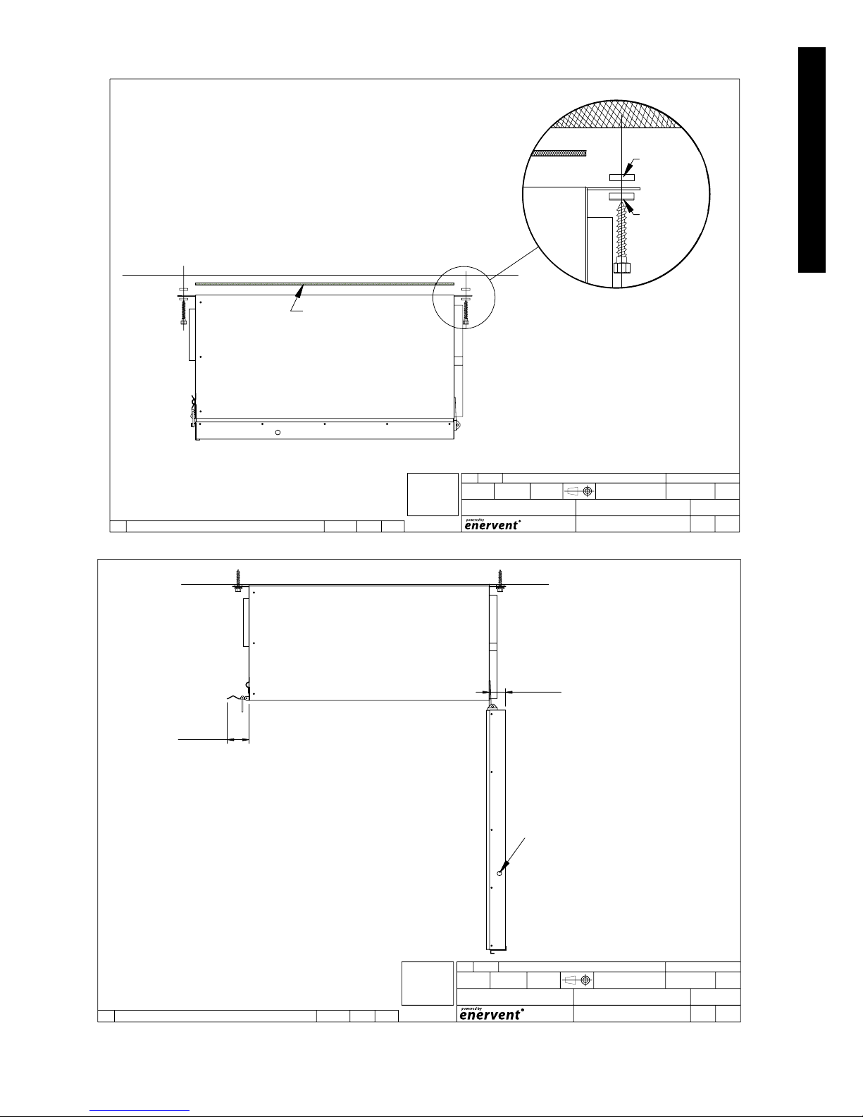
NOTE WHEN YOU INSTALL LIGGOLO MODELS:
J.T 01/10/2008 1:7
KATTOMALLI ASENNUSKUVA 002
1A
C:
Paino kg
HyvMuuttPvmMuutosNo
LehtiMuutosPiir no
Nimitys
SuhdePvmFileHyvTarkPiirt
ValmisteOsan nimitysKplOsa
EN ISO 13920-AE
YLEISTOLERANSSIT
Hitsatut rakenteet:
Koneistetut osat:
ISO 2768-MK
LIGGOLO
INSTALLATION PICTURE
E-mail: enervent@enervent.fi
Tel. 358-(0)207-528800
Fax. 358-(0)207-528844
Kipinätie1, 06150 Porvoo
DIN 571
8x60
4 pcs
Ceiling attachment
Ceiling
Foamed plastic 5mm
Rubber plate
Rubber plate +
Metal plate
J.T 01/10/2008 1: 7
KATTOMALLI ASENNUSKUVA 003
1A
C:
Paino kg
HyvMuuttPvmMuutosNo
LehtiMuutosPiir no
Nimitys
SuhdePvmFileHyvTarkPiirt
ValmisteOsan nimitysKplOsa
EN ISO 13920-AE
YLEISTOLERANSSIT
Hitsatut rakenteet:
Koneistetut osat:
ISO 2768-MK
LIGGOLO RIGHT
INSTALLATION PICTURE
E-mail: enervent@enervent.fi
Tel. 358-(0)207-528800
Fax. 358-(0)207-528844
Kipinätie1, 06150 Porvoo
Ceiling
~80mm
~45mm
Condense water drain
Page 10
10
INSTALLATION
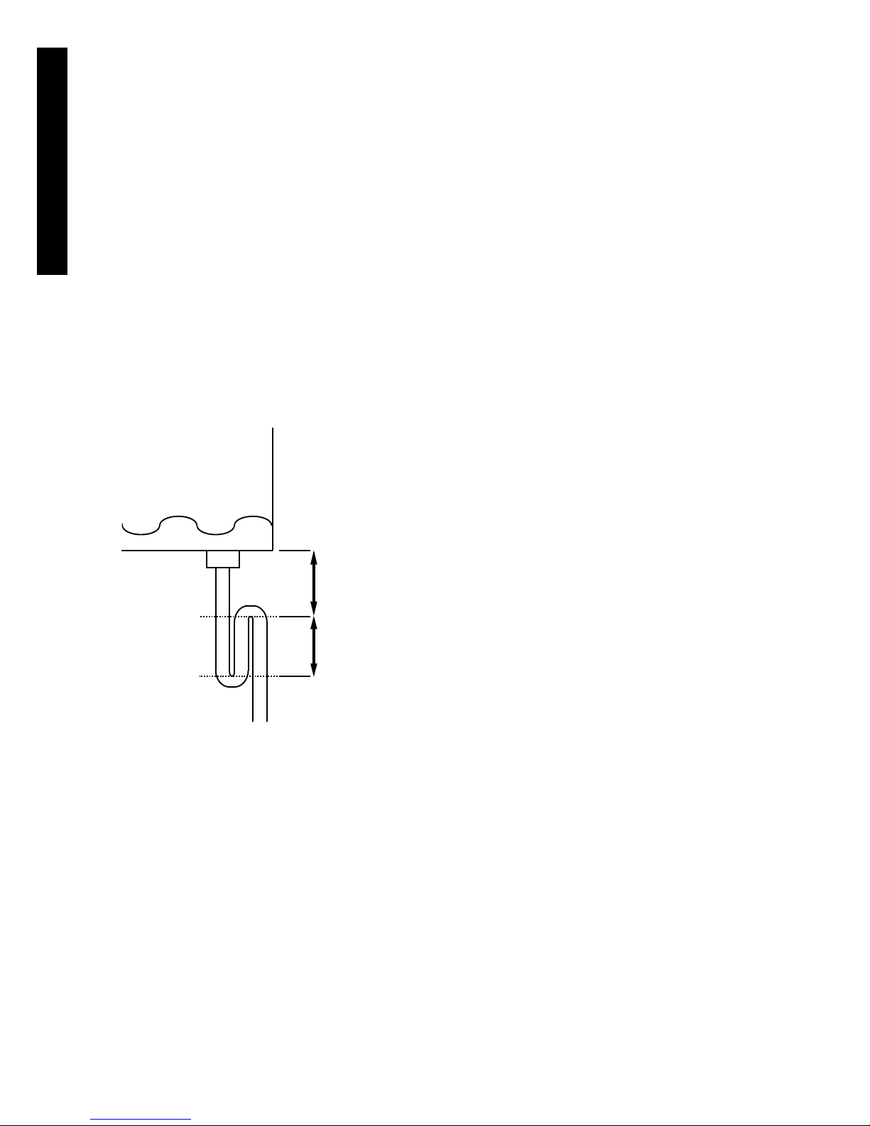
DRAINING THE VENTILATION UNIT
All Enervent Piccolo units must be drained. The condense water drain must not be directly connected to a sewer! The condense water should be led in a falling, at least Ø15 mm pipe, through a water lock to a oor drain or such. The pipe must
at all times lie lower than the bottom of the ventilation unit. There must not be any longer horizontal sections on the pipe
and there mustn’t be more than one water lock. If the unit is equipped with more than one condense water draines, each
one must have a water lock of its own.
There is under pressure in the ventilation unit. We recommend a hight dierence of (A) 75 mm, or at least the under pressure divided with 10 in millimeters (i.e. 500 Pa under pressure -> 50 mm), between the unit drain and the water lock drain.
We recommend that the hight of backwater in the water lock (B) is 50 mm, or at least the under pressure divided with
20 in millimeters (i.e. 500 Pa under pressure -> 25 mm hight of backwater). Over pressure is prevailing in a duct coil. We
recommend the hight dierence (A) between the duct coil drain and the water lock drain is 25 mm. The water lock hight
of backwater (B) must be 75 mm, or at least the under pressure divided wit 10 in millimeters (i.e. 500 Pa under pressure ->
50 mm). The water lock must be lled with water before starting up the unit. The water lock might dry up if water is not
accumulated in it. If this happens, ait might get into the pipe and hinder water from entering the water lock, which might
result in an irritating ”bubbling” sound.
The size of the condense water drain is 1/4” (inner thread) in all Piccolo units.
A
B
Page 11

11
Enervent® Piccolo EN 2011_1
USER GUIDE
USER GUIDE
STARTING THE UNIT
Before the unit is ready for use the following installations should take place:
- Assemble the unit and the cooker hood as stated in the chapter Installation in this manual. Check with a water
level to make sure that the unit is level, this is crucial for the drainage to work.
- Connect the drainage outlet with its own hose to an outow supplied with a water lock.
- Install the ducts (also for the cooker hood) and the silencers.
- Assemble the terminals on to the ducts.
- Provide the outside air duct with an outside air grating (N.B! the grating must not be provided with an insect net
because it is dicult to keep clean!)
- Make the roof pass-through. We recommend the use of a factory made, insulated roof pass-through.
- Insulate the ducts as instructed.
- Provide the unit with the appropriate power supply
Open the units maintenance hatch with the key provided when all the above mentioned installation work is done. Check
that the unit is clean on the inside, that there are no spare parts inside the unit and that the lters are clean. Close the
maintenance hatch carefully.
ABOUT VENTILATION
The ventilation unit should never be switched o. It is important to always ventilate with a high enough eect! If the ventilation is insucient the humidity indoors becomes too high and condensation can appear on, for instance, all the windows. A relative humidity of 40 - 45 % indoors is recommended (room temperature of 20 - 22°C). At these levels condensation will not form and the humidity will be at a healthy level. The humidity of a room can be measured with a hygrometer.
When the humidity rises above 45 % one should increase the ventilation and when the humidity goes lower than 40 % one
should lower the ventilation.
Check regularly that the lters are not dirty! During winter the exhaust lter become dirtier more quickly than the supply
air lter. As a result of this the airow lessens, which leads to lowered humidity indoors. This also leads to lower temperatures. Check the lters each month! At each lter inspection, check that the heat exchanger is functioning correctly, meaning
check that it is rotating. Cover both the outside air intake and the waste air outtake if the unit is not to be used for a longer
period. This way you stop moist from condensing on e.g. the fans electric motors.
Page 12

12
USER GUIDE
SUPPLY AND EXTRACT AIR CALIBRATION
After the unit has been switched on its airows must be calibrated to its planned values. When making the calibration all
lters should be clean, all supply and extract air valves, the roof pass-through and the outside air grating should be in place.
The outside air grating must not be provided with an insect net. The extract air ow should be ca. 5 - 10 % higher than
the supply air ow. To achieve optimal values during calibration the airows should be measured at each duct opening.
A suitable measuring instrument would be a thermo anemometer. With the help of registered values the airow can be
regulated to achieve the projected values. A correctly calibrated ventilation unit is quiet and gives a good heat return and
it also upholds a small under-pressure in the house. The under-pressure stops humidity from entering the walls and ceiling.
To make it easier to adjust the air amount the speed (-20 %...+10 %) of the supply air fan can be adjusted with the trimmer on the main switch board. The regulation is proportional for the dierent speed positions. I.e. the regulation -10 % on
speed setting 4 (100 %) means the extract air fan runs on 100 % and the supply air fan on 90 %, on speed setting 3 (80 %)
it means the exhaust air fan runs on 80 % and the supply air fan on 72 %, on speed setting 2 (60 %) it means the exhaust
air fan runs on 60 % and the supply air fan on 54 % and on speed setting 1 (40 %) it means the extract air fan runs on 40 %
and the supply air fan on 36 %. When the exhaust and supply air fan run on the same speed the speeds are (1) 40 %, (2) 60
%, (3) 80 % and (4) 100 %. Each of the speeds can be reduced max 20 % with the switch board trimmer. There are totally 5
trimmers on the board.
eco EC(E) units main board
15
10 20
LTO TEMP
The control panels
are connected here
(in either one).
External control connections
NOTE! MORE DETAILED CIRCUIT DIAGRAMS AT THE END OF THE MANUAL.
FAN SPEED CTRL
0 %
TF
DIFF
-20 %
+10 %
S1
20 %
30 %
40 %
S2
40 %
50 %
60 %
S3
60 %
80 %
70 %
S4
80 %
90 %
100 %
TF
CTRL
PF
CTRL
The heat recovery can be turned
off only when the outside air
temperature exceed +15°C (the
value can be set on the potentiometer on the control card)
Trimmers for regulating the air amount. The
regulation is proportional for the different speed
positions. I.e. the regulation -10% on speed setting
4 (100%) means the exhaust air fan runs on 100
% and the supply air fan on 90 %. Also read the
Ch. “Adjusting the proportion of supply air and
exhaust air”.
Page 13

13
Enervent® Piccolo EN 2011_1
USER GUIDE
Supply air filter
Extract air
filter
Supply air fan
Extract air fan
Heat recovery wheel
Resetting the electrical after
heater over heating protection
R
Supply air temperature
adjustment
Cooker hood damper control (A)
Knob with two functions (B/C):
Fan speeds controlled by turning the knob
Cooker hood light on/off by pushing the knob
USING AND CONTROLLING THE UNIT
The unit is intenden for continuous use. The unit’s air ow is
regulated with the right knob on the cooker hood.
The heat recovery is automatically controlled with an outside
air thermostat which starts and stops the heat recovery according to the outside air temperature. The factory setting is
+15°C. The setting can be changed with the trimmer on the
mother board. The heat recovery is on when the temperature
is beneath +15°C and o when the temperature is over +15°C.
The electrical after heater is controlled with a supply air thermostat. The factory setting is +18°C. The setting can be changed with the knob on the heater. The heater can not be on if
the heat reccovery is o.
On the front of the cooker hood is, besides control of the fan
speed, the control for the cooker hood damper. The damper
is opened during cooking by turning the left knob (A) on the
front of the cooker hood and the desired fan speed is set with
the right knob (B). The damper shuts automatically after 60
minutes and the unit resumes normal ventilation. Normal
ventilation can also be resumed by manually shutting the
damper.
Page 14

14
USER GUIDE
HEAT RECOVERY DEFROSTING FUNCTION
The defrosting of the heat recovery is active when the outside air temperature is lower than -15°C. The temperature is
checked every other hour (with 120 minutes interval). The supply air fan stops and the exhaust air fan runs on speed 3
when the defrosting is active. The defrosting is active at the most 8 % of the time. The over pressure function over rides
the defrosting function.
The defrosting function is activated by short circuiting the defrosting pins on the main board. The defrosting is in active when
the unit leaves the factory.
PF
CTRL
15
10 20
LTO TEMP
FAN SPEED CTRL
0 %
TF
DIFF
-20 %
+10 %
S1
20 %
30 %
40 %
S2
40 %
50 %
60 %
S3
60 %
80 %
70 %
S4
80 %
90 %
100 %
TF
CTRL
Defrosting
active
J1 J2
eco ECC units (with direct current fans):
Page 15

15
Enervent® Piccolo EN 2011_1
MAINTENANCE
The ventilation unit does not require any mechanical maintenance, only changing of the lters periodically and cleaning of
the heat exchanger and fans (when needed). Cut the power supply to the unit before starting any service work (from the
main switch or by removing the service hatch of the LTR-series units). Wait for two (2) minutes before starting the maintenance work! Although the unit’s power supply is cut when the hatch is opened, the fans still rotate and the electrical coil
in ECE-model is still hot for a while.
Cleaning the heat exchanger
When changing the lters, check if the heat exchanger is dirty. If cleaning is required, remove it from the unit and carefully
wash through the air channels with a hand shower using a mild detergent, taking care not to get the motor wet. The heat
exchanger can also be cleaned by blowing through the air channels using compressed air. Do not use a pressure washer
and do not submerge the heat exchanger into water!! When restarting the unit after cleaning, check that the heat exchanger wheel can turn freely.
Cleaning the fans
When changing lters, also check the condition of the fans. If cleaning is required the fans can be removed from the unit
and cleaned with a toothbrush or compressed air.
Changing of lters
The recommended time between lters changes for the cassette lter and the bag lter is six (6) months. If class F5 baglters are used the time between lter changes can be prolonged to one (1) year, by vacuuming the lters on the inside.
Remove the old lter and put in a new one. Vacuum cleaning the inside of the device is recommended at this point. N.B!
Make sure to close the service harch carefully!
Cleaning the cooker hood
The cooker hood is wipe with a damp cloth and washing liquid. The lter should be cleaned twice a month if the use is
normal. Loosen the lter cartridge by push the lock tags in the front edge. Take the lter apart and remove the lter cloth
by loosening the lter holder, picture 1. Soak the lter cloth and lter holder in warm water mixed with washing liquid. The
lter cartridge (with the cloth) can also be washed in a dish washer. The cooker hood should be cleaned inside some times
per year. Wipe the inside with a damp cloth and washing liquid. Put the lter cartridge back in place so that it locks in place.
Changing the luminescent lamp in the cooker hood
The lamp glas is loosened by push the lock tags in the direction shown by the arrow, picture 2. The luminescent lamp is
now accessable for change (luminescent lamp socket G23).
MAINTENANCE
Picture 1 Picture 2
Page 16
16
MAINTENANCE
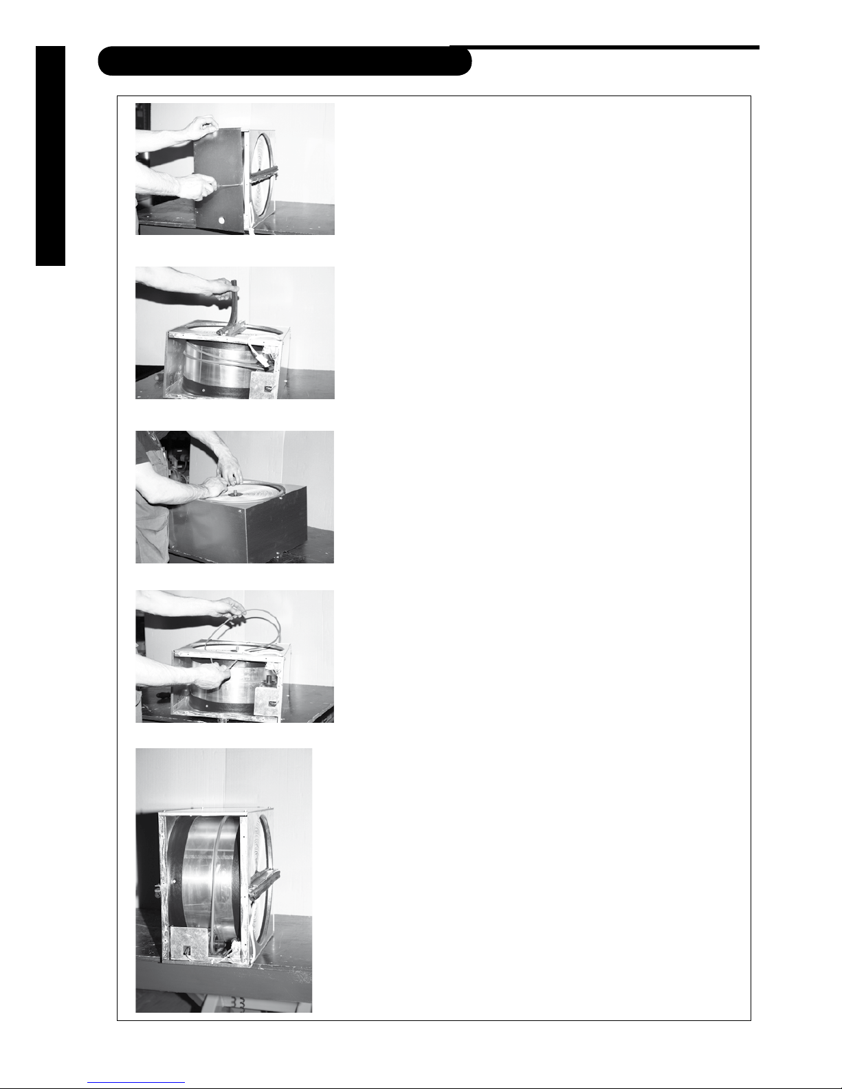
BELT REPLACEMENT
There is a spare belt in all heat exchangers. The spare belt is fixed
to the heat exchanger. In order to take the spare belt into use,
unplug the bayonet socket and remove the heat exchanger from
the ventilation unit. Open the service hatch (see below) and loosen
the spare belt from the holders. Leave the holders in the heat
exchanger. Pull the belt on to the belt holder. Close the service
hatch . Put the heat exchanger back into the ventilation unit and
connect the bayonett socket.
Follow the instructions below if there is no spare belt.
Turn of the ventilation unit by switching off the main power supply,
removing the fuse or disconnecting the wall plug.
Open the maintenance hatch.
Unplug the heat exchanger.
Pull out the heat exchanger from the ventilation unit.
Remove the lid by detaching the screws (pic 1).
pic 1
Turn the heat exchanger on to its side so that the axle is in a
vertical position. Remove the sealing strip (pic 2).
Detach the hexagonal screw and the screws in the u-beam.
Remove the u-beam.
Remove the old belt.
pic 2
Remove any possible dirt from the rotors surface and carefully
place the new belt inside the heat exchanger through outer shell
and the gasket (pic 3 and 4).
Carefully pull the belt past the gasket and rotate the rotor at the
same time. Assemble the u-beam.
Attach the beams screws and the hexagonal screw of the axle.
Put the belt on to the belt wheel and rotate the rotor away from
the motor a couple of times (pic 5).
Clean the inside of the heat exchanger.
Close the lid.
Re-assemble the heat exchanger in to the ventilation unit and
plug it in.
Turn on the ventilation unit and check that the heat exchanger is
rotating.
Close the maintenance hatch.
pic 3
pic 4
pic 5
Page 17
17
Enervent® Piccolo EN 2011_1
MAINTENANCE
TROUBLE SHOOTING
Reason Action
The heat exchanger switch is tuned o. Switch it on.
Belt of the heat exchanger broken. Replace the belt.
Belt greasy, causing slippage. Contact a service representative.
The exhaust fan has stopped. Contact a service representative.
The exhaust air lter is blocked. Change the lters.
Exhaust air valve settings incorrect. Contact a service representative.
Heat insulation of ducts inadequate. Check the insulation thickness of the supply and ex-
haust air ducts and add insulation if needed.
The after heater over heating protection has gone
o (ECE-models).
Check what the reason to the problem is and reset the
over heating protection.
SUPPLY AIR TOO COLD
REDUCED AIR FLOW
Reason Action
Filters are blocked. Change the lters.
Too small a fan speed is selected. Select higher speed.
Blockage in the fresh air grille. Clean the outer grille.
Fan wings dirty. Clean the fans.
TECHNICAL INFORMATION
UNIT:
(without cooker hood)
PICCOLO eco ECE-ON PICCOLO eco ECE-OFF LIGGOLO eco ECE
Width
Depth
Hight
598 mm
320 mm
630 mm
598 mm
320 mm
700 mm
598 mm
630 mm
350 mm
Weight
46 kg 46 kg 46 kg
Duct size
Ø 125 mm Ø 125 mm Ø 125 mm
Fans supply and extract air
119 W
0,9 A
119 W
0,9 A
119 W
0,9 A
Electrical after heater
800 W 800 W 800 W
Current
Fuse
Main board glas pipe fuse 5x20 mm
230 V~, 50 Hz
10 A quick
F1 T1,6 A
230 V~, 50 Hz
10 A quick
F1 T1,6 A
230 V~, 50 Hz
10 A quick
F1 T1,6 A
Heat exchanger motor
8 W, 0.035 A 8 W, 0.035 A 8 W, 0.035 A
INCREASED OPERATING SOUND LEVEL
Reason Action
Filters blocked. Change the lters.
Outer grilles are blocked. Clean the outer grille .
Fan bearings faulty. Change bearings / contact service.
Fan wings dirty. Clean the fans.
Problem with gear/motor of the heat exchanger. Contact a service representative.
Page 18
18
TECHNICAL INFORMATION
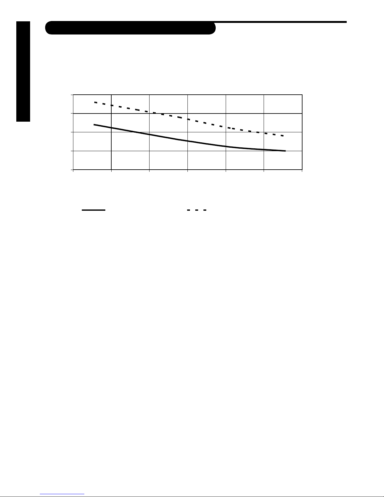
HEAT RECOVERY EFFICIENCY
ENERVENT® PICCOLO
HEAT RECOVERY TEMPERATURE EFFICIENCY
70
75
80
85
90
0 10 20 30 40 50 60
Air flow l/s
η
%
Supply/extract ratio 1.0 Supply/extract ratio 0.85
88%
82%
75%
79%
Page 19

19
Enervent® Piccolo EN 2011_1
TECHNICAL INFORMATION
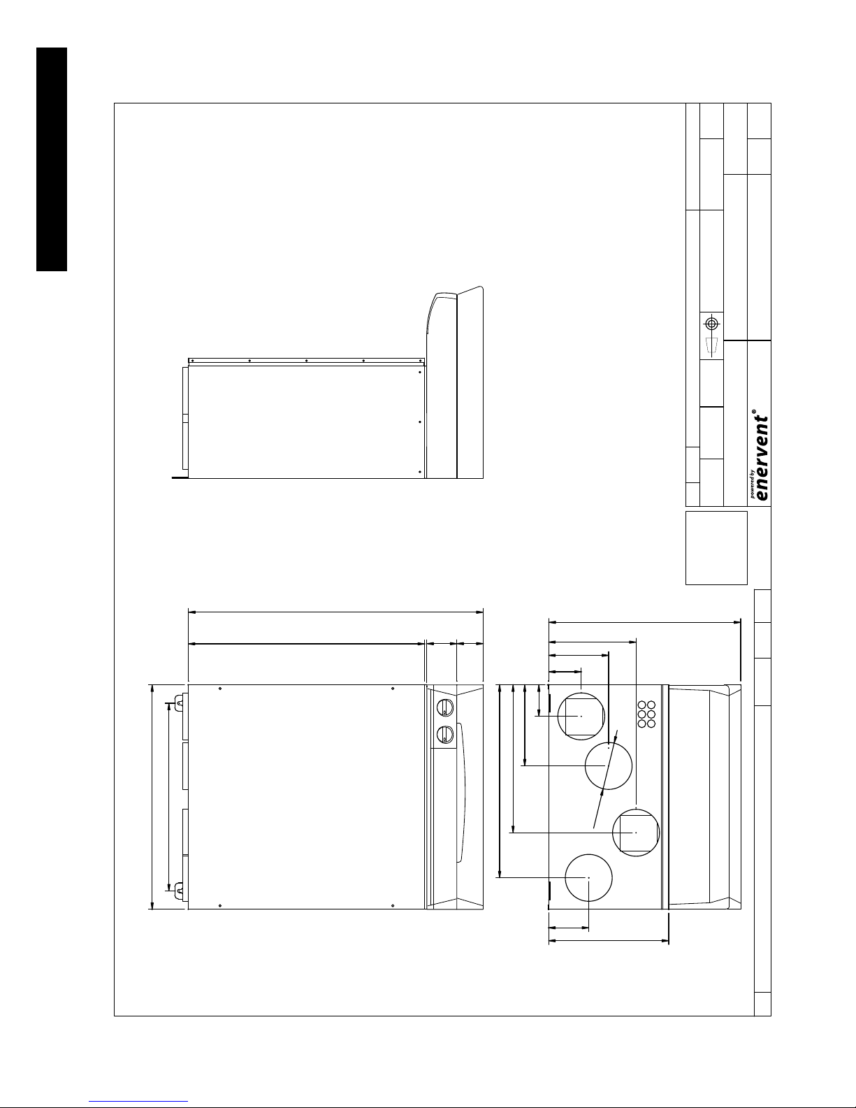
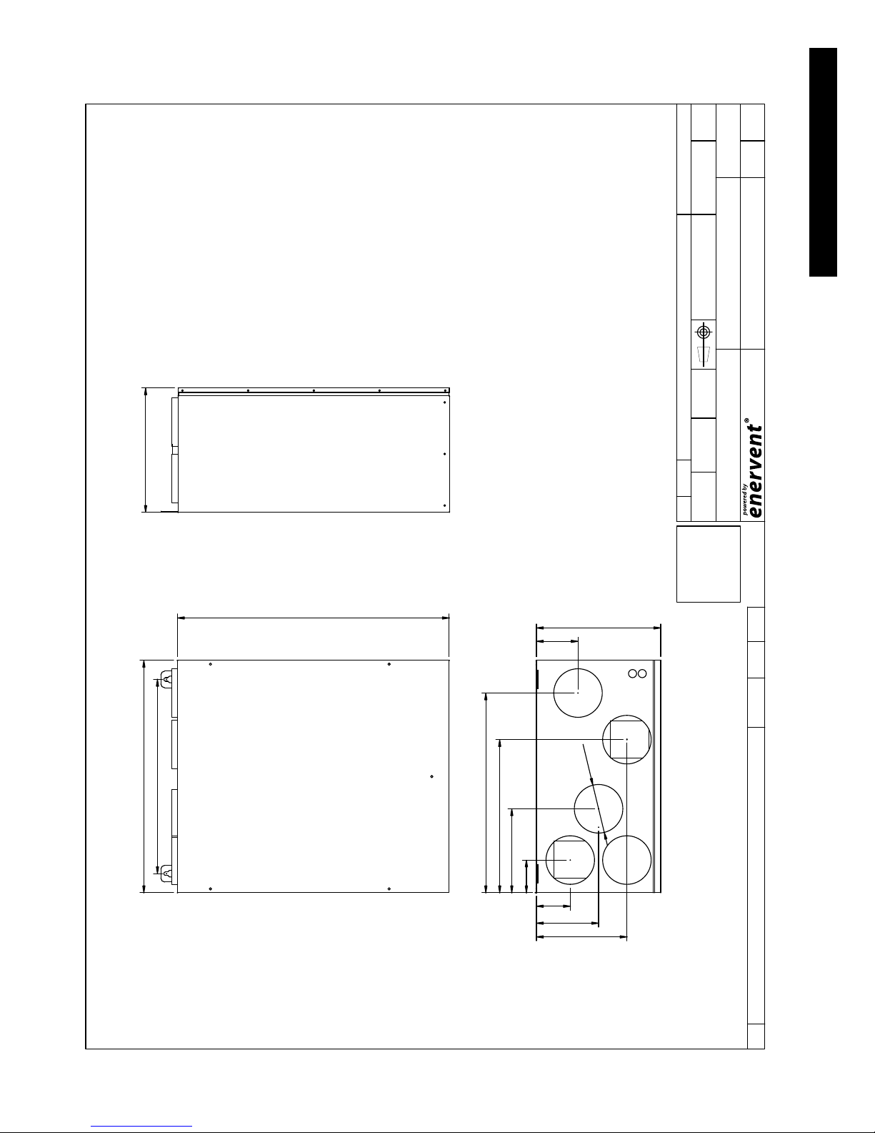
DIMENSION DRAWINGS
DIMENSION DRAWING
PICCOLO ON RIGHT
ISO 2768-MK
YLEISTOLERANSSIT
Hitsatut rakenteet:
EN ISO 13920-AE
Koneistetut osat:
Lehti
Suhde
Valmiste
Pvm
Paino kg
MuutosPiir no
Nimitys
FileHyvPiirt Tark
Osan nimitysKplOsa
HyvMuuttPvmMuutosNo
C:
E 1
71:17/08/2006J.T
785
80
630
598
500
514
320
87
394
84
160
216
233
Ø 125
107
511
EXHAUST AIR
OUTSIDE AIR
SUPPLY AIR
EXTRACT AIR
70
MH-007
E-mail: enervent@enervent.
Tel. 358-(0)207-528800
Fax. 358-(0)207-528844
Kipinätie1, 06150 Porvoo
SERVICE HATCH
Page 20
20
TECHNICAL INFORMATION
J.T 17/08/2006 1: 7
MH-008 1D
C:
No Muutos Pvm Muutt Hyv
Osa Kpl Osan nimitys
TarkPiirt Hyv File
Nimitys
Piir no Muutos
Paino kg
Pvm
Valmiste
Suhde
Lehti
EXHAUST AIR
OUTSIDE AIR
SUPPLY AIR
EXTRACT AIR
Koneistetut osat:
EN ISO 13920-AE
Hitsatut rakenteet:
YLEISTOLERANSSIT
ISO 2768-MK
PICCOLO ON LEFT
DIMENSION DRAWING
514
320
87
394
84
160
216
233
Ø 125
598
630
107
500
785
80
511
70
E-mail: enervent@enervent.
Tel. 358-(0)207-528800
Fax. 358-(0)207-528844
Kipinätie1, 06150 Porvoo
SERVICE HATCH
Page 21
21
Enervent® Piccolo EN 2011_1
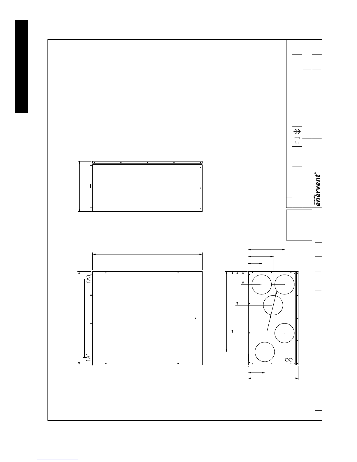
TECHNICAL INFORMATION
OUTSIDE AIR
EXTRACT AIR
SUPPLY AIR
EXHAUST AIR
500
700
598
320
J.T 17/11/2008 1: 7
MH-011 1A
U:\VAKIOT
M)\PICCOLO
Paino kg
HyvMuuttPvmMuutosNo
LehtiMuutosPiir no
Nimitys
SuhdePvmFileHyvTarkPiirt
ValmisteOsan nimitysKplOsa
EN ISO 13920-AE
YLEISTOLERANSSIT
Hitsatut rakenteet:
Koneistetut osat:
ISO 2768-MK
PICCOLO OFF RIGHT
DIMENSION DRAWING
514
320
87
394
84
160
216
233
Ø 125
107
COOKER HOOD
SERVICE HATCH
E-mail: enervent@enervent.
Tel. 358-(0)207-528800
Fax. 358-(0)207-528844
Kipinätie1, 06150 Porvoo
Page 22
22
TECHNICAL INFORMATION
J.T 17/11/2006 1: 7
MH-012 1A
Paino kg
HyvMuuttPvmMuutosNo
LehtiMuutosPiir no
Nimitys
SuhdePvmFileHyvTarkPiirt
ValmisteOsan nimitysKplOsa
OUTSIDE AIR
EN ISO 13920-AE
YLEISTOLERANSSIT
Hitsatut rakenteet:
Koneistetut osat:
ISO 2768-MK
PICCOLO OFF LEFT
DIMENSION DRAWING
514
320
87
394
84
160
216
233
320
Ø 125
EXTRACT AIR
SUPPLY AIR
EXHAUST AIR
COOKER HOOD
598
700
107
500
SERVICE HATCH
U:\VAKIOT
M)\PICCOLO
E-mail: enervent@enervent.
Tel. 358-(0)207-528800
Fax. 358-(0)207-528844
Kipinätie1, 06150 Porvoo
Page 23
23
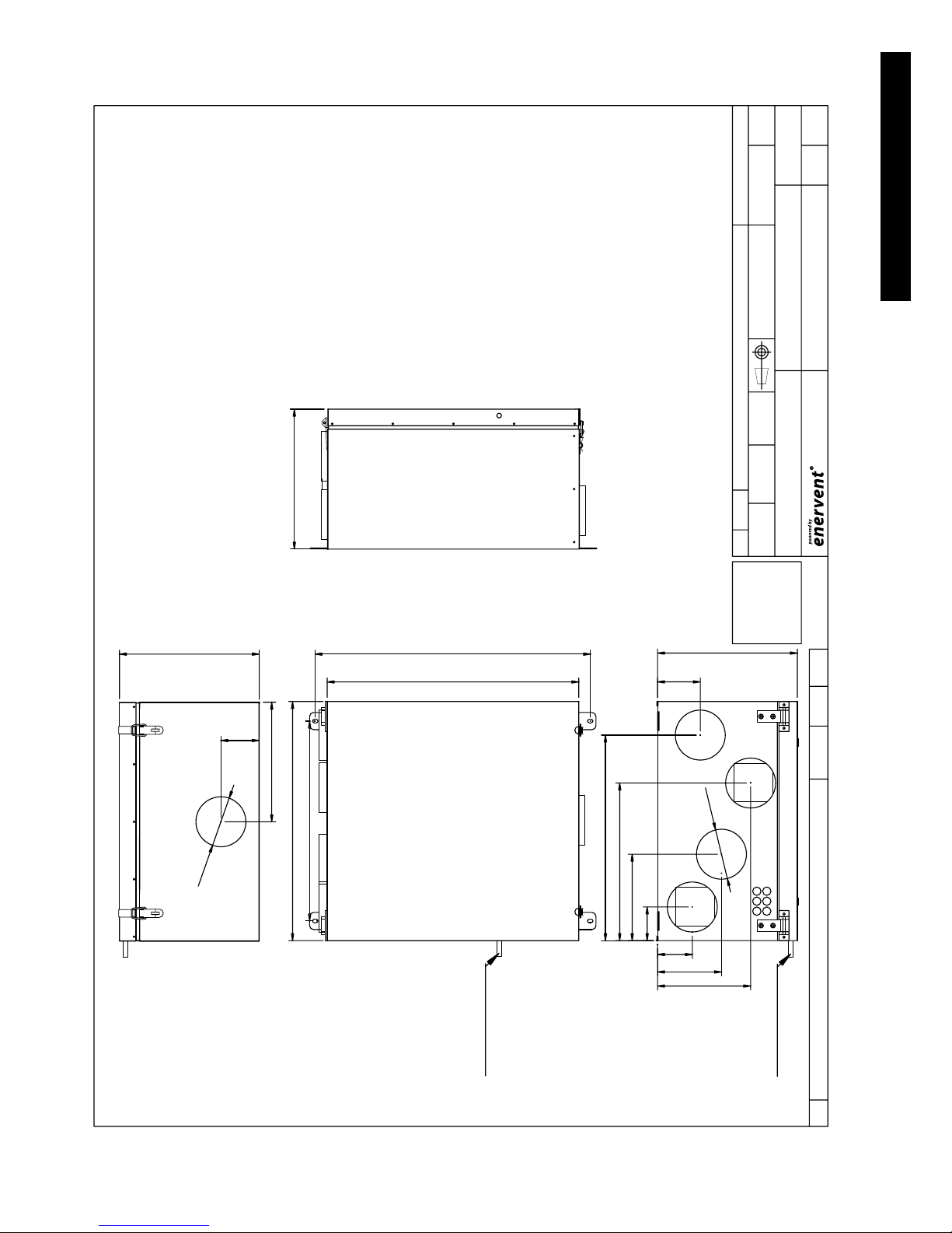
Enervent® Piccolo EN 2011_1
TECHNICAL INFORMATION
OUTSIDE AIR
EXTRACT AIR
SUPPLY AIR
EXHAUST AIR
COOKER
HOOD
96
299
Ø 125
350
630
598
350
J.T 02/10/2008 1: 7
1A
C:
Paino kg
HyvMuuttPvmMuutosNo
LehtiMuutosPiir no
Nimitys
SuhdePvmFileHyvTarkPiir t
ValmisteOsan nimitysKplOsa
EN ISO 13920-AE
YLEISTOLERANSSIT
Hitsatut rakenteet:
Koneistetut osat:
ISO 2768-MK
LIGGOLO RIGHT
DIMENSION DRAWING
514
350
87
394
84
160
216
233
Ø 125
107
SERVICE HATCH
500
690
E-mail: enervent@enervent.fi
Tel. 358-(0)207-528800
Fax. 358-(0)207-528844
Kipinätie1, 06150 Porvoo
KATTOMALLI 002
CONDENSE WATER DRAIN
CONDENSE WATER DRAIN
CONDENSE WATER DRAIN
Page 24

24
TECHNICAL INFORMATION
J.T 01/10/2008 1: 7
1A
C:
Paino kg
HyvMuuttPvm
MuutosNo
LehtiMuutosPiir no
Nimitys
SuhdePvmFileHyvTarkPiirt
ValmisteOsan nimitysKplOsa
OUTSIDE AIR
EN ISO 13920-AE
YLEISTOLERANSSIT
Hitsatut rakenteet:
Koneistetut osat:
ISO 2768-MK
LIGGOLO LEFT
DIMENSION DRAWING
514
350
87
394
84
160
216
233
350
Ø 125
EXTRACT AIR
SUPPLY AIR
EXHAUST AIR
598
630
350
107
COOKER HOOD
Ø 125
299
96
SERVICE HATCH
500
E-mail: enervent@enervent.fi
Tel. 358-(0)207-528800
Fax. 358-(0)207-528844
Kipinätie1, 06150 Porvoo
690
CONDENSE WATER DRAIN
CONDENSE WATER DRAIN
KATTOMALLI 001
Page 25
25
Enervent® Piccolo EN 2011_1
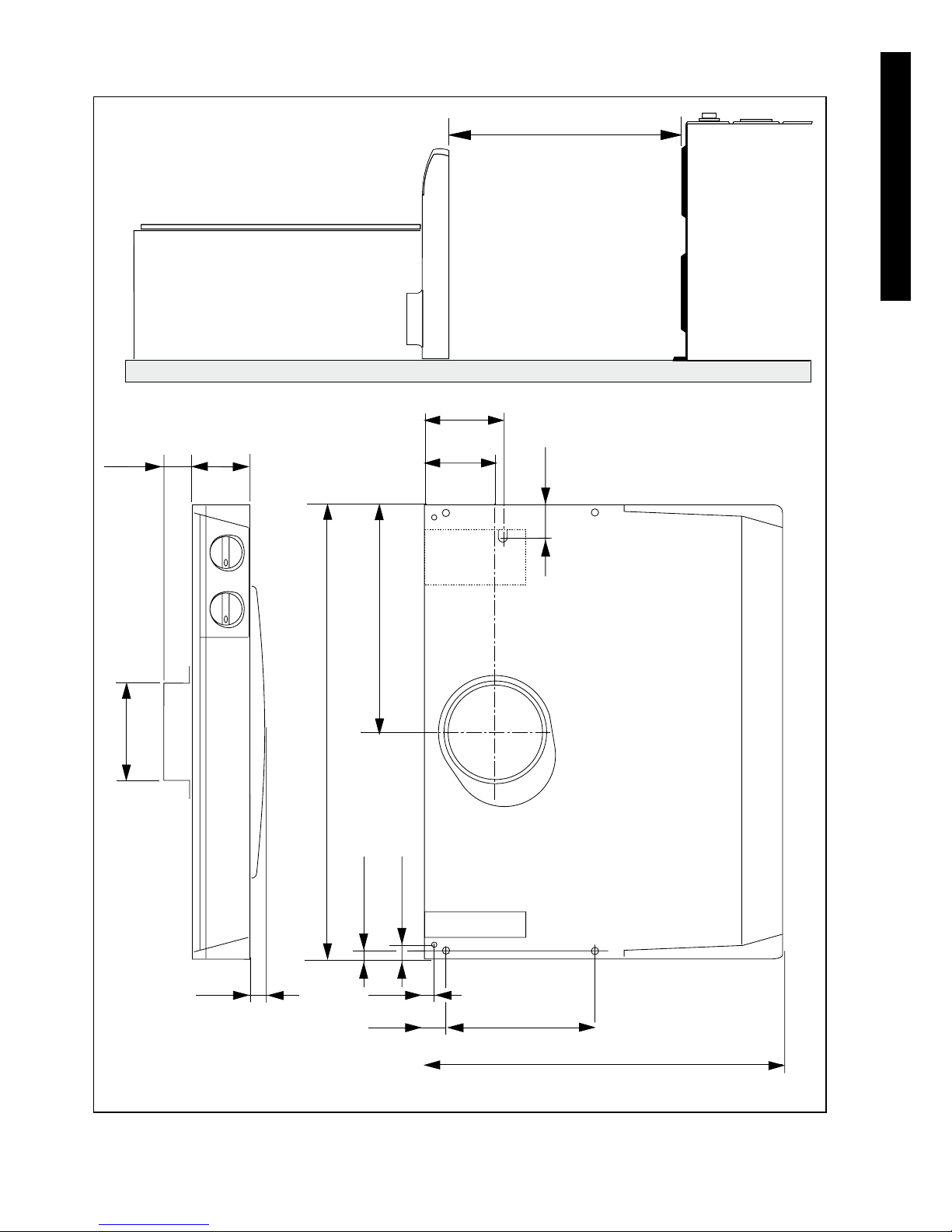
TECHNICAL INFORMATION
Ø 125
22
40
80
598
300
9,5
16
13
50
190
480
38
98
104
400/650
Page 26

26
TECHNICAL INFORMATION
CHARACTERISTIC CURVES
Piccolo/Liggolo ec o E CE fan power input with
F7 cassette filter in supply air and F5 bag filter in extract air
0
10
20
30
40
50
60
70
80
90
100
0 1 0 2 0 30 4 0 50 6 0 70 8 0 90
Air amount l/s
Power input W
90%
50%
100%
80%
70%
60%
40%
30%
20%
EXTRACT AIR
SUPPLY AIR
0
50
100
150
200
250
300
0 1 0 20 3 0 40 50 6 0 70 80 9 0
Air amount l/s
Available pressure P a
SUPPLY AIR
EXTRACT AIR
80 %
60 %
50 %
40 %
30 %
20 %
90 %
10 0%
70 %
Piccolo/Liggolo eco ECE supply and extract air characteristic curves with F7/F5 filter
Page 27

27
Enervent® Piccolo EN 2011_1
TECHNICAL INFORMATION
SOUND DATA
PICCOLO SOUND LEVEL IN OUTSIDE AIR DUCT
• Supply air filter F7, 281x436x29 mm (+ 3 mm)
• Extract air filter F5, 275x121-175/5
• Supply and exhaust air fan; Ebm Papst G3G146-ED23-06
Sound level in outside air duct. Heat exchanger rotating.
U(%) 2 0 % 3 0 % 4 0 % 5 0 % 6 0 % 7 0 % 8 0 % 90% 10 0 %
qv (l/s) 4 9 17 28 3 8 4 8 55 67 74
L
W6 3
, dB
L
W1 25
, dB
L
W2 50
, dB
L
W5 00
, dB
L
W1 00 0
, dB
L
W2 00 0
, dB
L
W4 00 0
, dB
L
W8 00 0
, dB
18
17
20
26
13
10
12
17
25
22
22
29
14
10
12
17
33
31
26
32
21
10
12
17
39
36
32
36
25
15
13
17
44
42
37
40
29
20
16
18
48
47
42
44
33
25
20
18
49
50
46
47
36
29
24
18
52
53
49
50
38
34
27
19
52
54
49
51
39
35
29
19
LW, dB
LWA, d B(A)
28
25
32
27
38
30
42
34
47
39
52
43
55
46
57
49
58
49
Character descript ion:
U (%) Fan spe ed settin g, V
q
V
Air fl ow, dm³/s
L
W6 3. ..8 00 0
Uni t octave e ffect ba nd
w 63 ... 80 00
O ctave b and mid f requenc y, Hz
LW Sound e f fect level, dB
LWA A - weighed so u nd effec t level, dB(A)
LpA A-weighed sound pre s sure level ( 10 m2 sound abs o rption) , dB(A)
PICCOLO SOUND LEVEL IN SUPPLY AIR DUCT
• Supply air filter F7, 281x436x29 mm (+ 3 mm)
• Extract air filter F5, 275x121-175/5
• Supply and exhaust air fan; Ebm Papst G3G146-ED23-06
Sound level in supply air duct. Heat exchanger rotating.
U(%) 2 0 % 3 0 % 4 0 % 5 0 % 6 0 % 7 0 % 8 0 % 90% 10 0 %
qv (l/s) 4 9 17 28 3 8 4 8 55 67 74
L
W6 3
, dB
L
W1 25
, dB
L
W2 50
, dB
L
W5 00
, dB
L
W1 00 0
, dB
L
W2 00 0
, dB
L
W4 00 0
, dB
L
W8 00 0
, dB
29
30
30
31
20
12
14
17
34
35
36
36
34
27
16
18
39
40
41
44
44
38
29
18
44
47
48
49
50
46
38
22
49
52
52
52
54
52
44
30
54
57
57
56
57
56
49
37
55
60
61
59
60
60
53
43
57
63
63
62
62
62
55
47
59
63
64
63
63
63
57
48
LW, dB
LWA, d B(A)
36
30
42
38
49
47
55
53
60
58
64
62
67
65
70
67
71
68
Page 28

28
TECHNICAL INFORMATION
PICCOLO SOUND LEVEL IN EXTRACT AIR DUCT
• Supply air filter F7, 281x436x29 mm (+ 3 mm)
• Extract air filter F5, 275x121-175/5
• Supply and exhaust air fan; Ebm Papst G3G146-ED23-06
Sound level in extract air duct. Heat exchanger rotating.
U(%) 2 0 % 3 0 % 4 0 % 5 0 % 6 0 % 7 0 % 8 0 % 90% 10 0 %
qv (l/s) 4 9 17 28 3 8 4 8 55 67 74
L
W6 3
, dB
L
W1 25
, dB
L
W2 50
, dB
L
W5 00
, dB
L
W1 00 0
, dB
L
W2 00 0
, dB
L
W4 00 0
, dB
L
W8 00 0
, dB
13
14
13
13
14
14
16
19
18
19
15
16
15
12
14
18
32
33
32
31
31
19
13
18
37
38
37
36
35
15
16
18
40
41
40
40
40
30
21
18
43
44
43
43
42
34
25
18
45
47
47
47
45
38
28
23
46
48
50
49
47
41
31
26
47
49
51
50
48
41
32
27
LW, dB
LWA, d B(A)
24
22
25
22
39
34
44
38
47
43
50
45
53
49
55
51
56
52
Character descript ion:
U (%) Fan spe ed settin g, V
q
V
Air fl ow, dm³/s
L
W6 3. ..8 00 0
Uni t octave e ffect ba nd
w 63 ... 80 00
O ctave b and mid f requenc y, Hz
LW Sound e f fect level, dB
LWA A - weighed so u nd effec t level, dB(A)
LpA A-weighed sound pre s sure level ( 10 m2 sound abs o rption) , dB(A)
PICCOLO SOUND LEVEL IN EXHAUST AIR DUCT
• Supply air filter F7, 281x436x29 mm (+ 3 mm)
• Extract air filter F5, 275x121-175/5
• Supply and exhaust air fan; Ebm Papst G3G146-ED23-06
Sound level in exhaust air duct. Heat exchanger rotating.
U(%) 2 0 % 3 0 % 4 0 % 5 0 % 6 0 % 7 0 % 8 0 % 90% 10 0 %
qv (l/s) 4 9 17 28 3 8 4 8 55 67 74
L
W6 3
, dB
L
W1 25
, dB
L
W2 50
, dB
L
W5 00
, dB
L
W1 00 0
, dB
L
W2 00 0
, dB
L
W4 00 0
, dB
L
W8 00 0
, dB
29
30
30
31
20
12
14
17
34
35
34
36
35
27
14
18
39
40
41
44
44
38
29
18
47
45
46
48
51
45
36
19
50
50
51
52
55
52
43
26
52
54
54
56
58
57
47
33
55
56
57
59
60
60
51
39
58
58
59
61
62
63
54
43
59
59
60
62
63
64
55
44
LW, dB
LWA, d B(A)
36
30
42
38
49
47
55
53
60
58
64
62
66
65
69
67
70
68
Page 29

29
Enervent® Piccolo EN 2011_1
TECHNICAL INFORMATION
Character descript ion:
U (%) Fan spe ed settin g, V
qV Air fl ow, dm³/s
L
W6 3. ..8 00 0
Uni t octave e ffect ba nd
w 63 ... 80 00
O ctave b and mid f requenc y, Hz
LW Sound e f fect level, dB
LWA A - weighed so u nd effec t level, dB(A)
LpA A-weighed sound pre s sure level ( 10 m2 sound abs o rption) , dB(A)
PICCOLO SOUND LEVEL IN SURROUNDING
• Supply air filter F7, 281x436x29 mm (+ 3 mm)
• Extract air filter F5, 275x121-175/5
• Supply and exhaust air fan; Ebm Papst G3G146-ED23-06
Sound level through casing, with cooker hood attached (damper shut). Heat exchanger is rotating.
U(%) 2 0 % 3 0 % 4 0 % 5 0 % 6 0 % 7 0 % 8 0 % 90% 10 0 %
qv (l/s)
Suppl y air
Extract air
10
11
17
19
25
28
33
36
42
46
47
50
51
56
60
65
64
68
L
W6 3
, dB
L
W1 25
, dB
L
W2 50
, dB
L
W5 00
, dB
L
W1 00 0
, dB
L
W2 00 0
, dB
L
W4 00 0
, dB
L
W8 00 0
, dB
31
33
24
22
16
10
13
17
37
40
30
27
21
17
15
18
42
46
36
32
26
18
15
14
46
52
41
35
30
21
13
14
51
56
44
39
33
26
17
17
52
57
46
40
34
28
18
18
53
60
49
42
35
29
20
18
55
62
52
44
38
32
23
20
57
61
53
45
38
32
24
21
LW, dB
LWA, d B(A)
LpA, dB(A)
36
24
20
43
30
26
48
35
31
53
39
35
58
43
39
59
44
40
61
47
43
63
49
45
63
49
45
Page 30

30
TECHNICAL INFORMATION
CONTROL CHARTS
FI01
FI03
LHRW
M1
TE01
INTERNAL FEED AND CONTROL SWITCHES
RK (SU)
WALL PLUG
230VAC 10 A
SILENCER
SILENCER
Q1 = SPEED
Q1
COOKER HOOD
EHC45
TS2
DIP SWITCH
MuutosNo MuuttPvm Hyv
Piirt
Osa
Osan nimitys
Tark
Kpl
Hyv
Piir no
Nimitys
File
Paino kg
Muutos
Pvm
Valmiste
Lehti
Suhde
MW
PICCOLO ECO ECE
CONTROL CHART
A
08.10.2009
Piccolo ECO ECE
SC
10
SC
30
EF
10
SF
M
30
M
ESES
+
45
TZA+
45
TZ+
ESES
Tel. 358-(0)207-528800
Kipinätie1, 06150 Porvoo
Fax. 358-(0)207-528844
E-mail: enervent@enervent.
MEASURING
ADJUSTMENT
CONTROL
STATUS
ALARM
MEASURING
ADJUSTMENT
CONTROL
STATUS
ALARM
= CABELING AND CONNECTION AT SITE (EE)
= PHYSICAL CONNECTION
= PROGRAM FUNCTION
Page 31

31
Enervent® Piccolo EN 2011_1
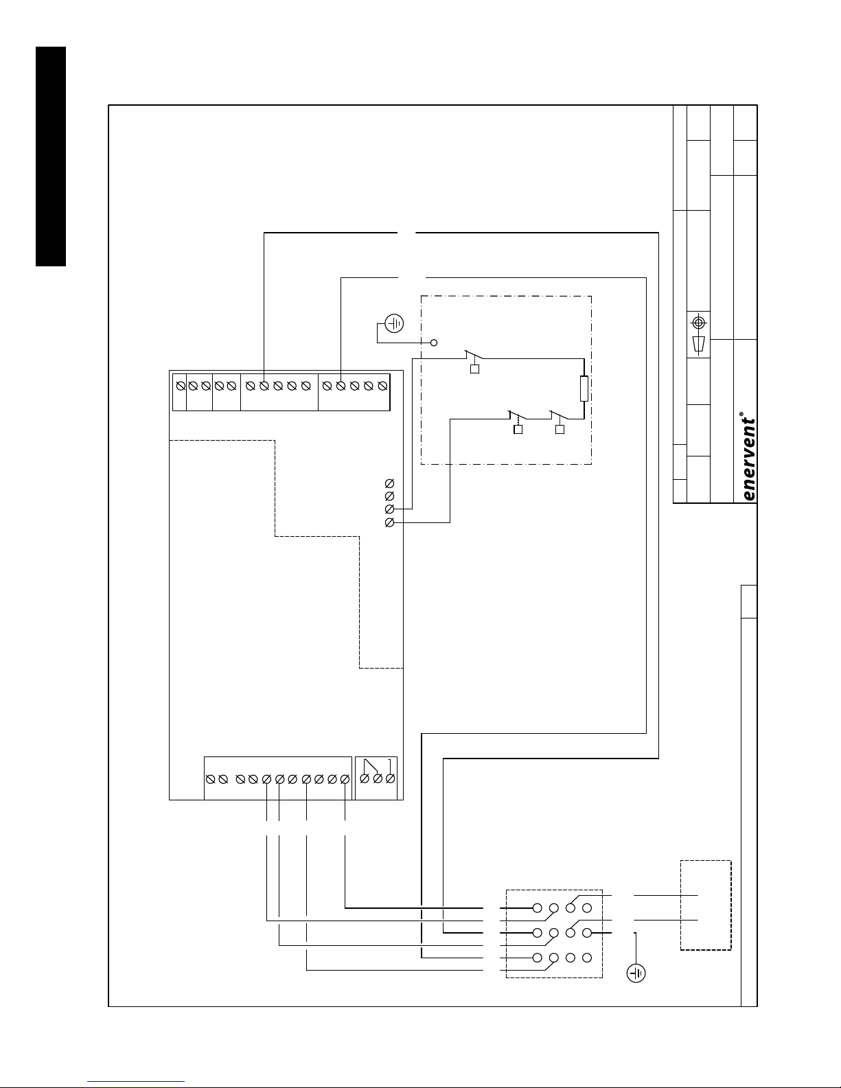
TECHNICAL INFORMATION
MW
PICCOLO/LIGGOLO ECO ECE
17.02.2010
M
NL
L N
NL
SF
EF
C1
T2 T1
RJ11
LTO TEMP
10-20 C
T3
AFT
HEAT
LTO
F1
S2
STOP
LTOC
COM
S1
S4
S3
OVERP
ALARM
RJ11
NC
COM
NO
L N
PFTF
CTRL CTRL
S2
FAN SPEED CTRL
S1
TF DIFF
S3
S4
-20-0 %
80-100 %
40-60 %60-80 % 20-40 %
230 VAC, 50 Hz
24 VAC
2 1 PE PE12 PE21
NNN
L
NNL
LLL
SW
L
L
IN
SW
N
N IN
PE
OUTSIDE AIR
SENSOR
CONNECTION FOR SPEED
SEE PAGE 2
CONNECTION FOR ELECTRICAL HEATER SEE PAGE 2
SUPPLY 10 A, 230 VAC
WALLPLUG SUPPLY
FOR EXTERNAL CONTROL
CONNECTIONS
POTENTIALFREE CONTACT
(MAX 35V)
SWITCH
ALARM
FREEZEALARM)
OVERPRESSURE
EXTERNAL
(FIREDANGER,
AH-E-STOP
COOLING
RECOVERY
FAULT OUTPUT
(MAX 250VAC/1A)
MOTOR
EXHAUSTFAN
MOTOR
SUPPLYFAN
MOTOR
HRW
-
+
+
1212
SF
0-10V
EF
0-10V
CONTROLCONTROL
Piccolo ECO ECE
DCC-06/ DCC-06E
ELECTRICAL CONNECTIONS
Osa Kpl Osan nimitys Valmiste
Piirt Tark Hy v File Pvm
Nimitys
Piir no
Hyv
Tel. 358-(0)207-528800
Kipinätie1, 06150 Porvoo
Fax. 358-(0)207-528844
E-mail: enervent@enervent.
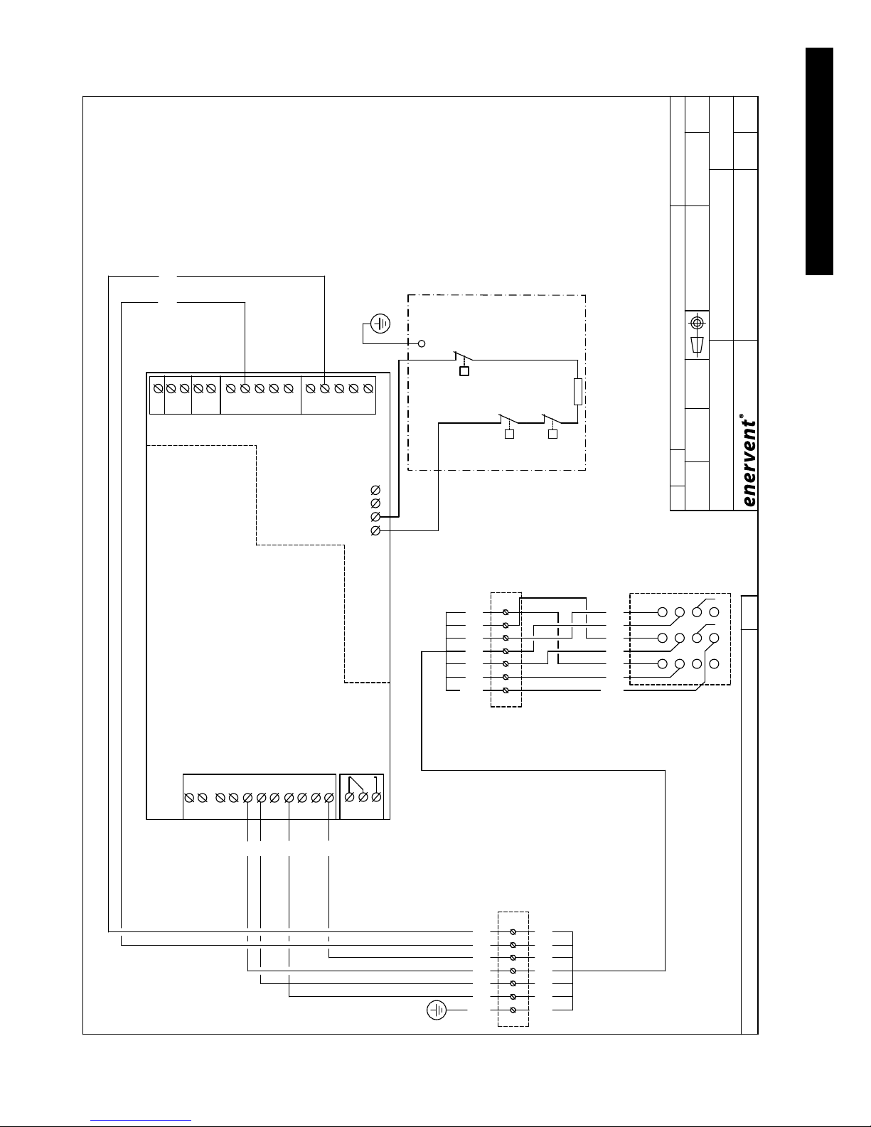
WIRING DIAGRAMS
Page 32
32
TECHNICAL INFORMATION
MW 2
NL
L N
AFT
HEAT
LTO
S2
STOP
LTOC
COM
S1
S4
S3
OVERP
ALARM
NC
COM
NO
NNN
L
NNL
LLL
SW
L
L
IN
SW
N
N IN
PE
PICCOLO (ECO) ECE
17.02.2010
230 VAC, 50 Hz
24 VAC
ELECTRICAL HEATER
18°C
OVERHEATING-
PROTECTION
THERMOSTAT
IN SUPPLYAIR
MANUAL
AUTOMATIC
OVERHEATING-
PROTECTION
CONNECTOR
1 2 3
654
7 8 9
121110
YeGr
8 321 6
8 6
5123
5
47
NOT CONNECTED
Piccolo ECO ECE
ECC-05/ECC-05E or DCC-05/DCC-05E
ELECTRICAL CONNECTIONS
RANGE HOOD 251-12
Osa Kpl Osan nimitys Valmiste
Piirt Tark Hyv File Pvm Sivu
Nimitys
Piir no Muutos Lehti
Hyv
Paino kg
Tel. 358-(0)207-528800
Kipinätie1, 06150 Porvoo
Fax. 358-(0)207-528844
E-mail: enervent@enervent.
T
TZA+
2
C
T
TZ+
1
C
T
TS2
1
C
800 W
Page 33
33
Enervent® Piccolo EN 2011_1
TECHNICAL INFORMATION
MW 2
NL
L N
AFT
HEAT
LTO
S2
STOP
LTOC
COM
S1
S4
S3
OVERP
ALARM
NC
COM
NO
NNN
L
NNL
LLL
SW
L
L
IN
SW
N
N IN
PE
PICCOLO/LIGGOLO (ECO) ECE
15.11.2010
230 VAC, 50 Hz
24 VAC
ELECTRICAL HEATER
18°C
OVERHEATING-
PROTECTION
THERMOSTAT
IN SUPPLYAIR
MANUAL
AUTOMATIC
OVERHEATING-
PROTECTION
YeGr
2 631 5
86
5123
8
CONNECTOR
1 2 3
654
7 8 9
121110
YeGr
8 321 6 5
4
7
YeGr
2 631 5 8
YeGr
2 631 5 8
AP9
AP9
Connection at site
( Ex. MMO 7x1.5 S )
Piccolo ECO ECE
RANGE HOOD 250-10
ECC-05/ECC-05E or DCC-05/DCC-05E
ELECTRICAL CONNECTIONS
Osa Kpl Osan nimitys Valmiste
Piirt Tark Hy v File Pvm Sivu
Nimitys
Piir no Muutos Lehti
Hyv
Paino kg
Tel. 358-(0)207-528800
Kipinätie1, 06150 Porvoo
Fax. 358-(0)207-528844
E-mail: enervent@enervent.
T
TZA+
2
C
T
TZ+
1
C
T
TS2
1
C
81 2
6
3 5PE
81 2
6
3 5PE
800 W
Page 34

34
DECLARATION OF CONFORMITY
We declare that our products follows the provisions of low voltage directive (LVD) 2006/95/EY, EMC-directive 2004/108/
EY and machine directive (MD) 98/37/EY.
Manufacturer: Enervent Oy
Manufacturer´s contact: Kipinätie 1, 06150 PORVOO, FINLAND
tel +358 (0)207 528 800, fax +358 (0)207 528 844
enervent@enervent., www.enervent.
Description of the product: Ventilation unit with heat recovery
Trade name of the product: Enervent Piccolo eco ECE
Enervent Liggolo eco ECE
Representatives for the products in the region of EU:
Sweden: Ventener Ab, Örelidsvägen 10, 517 71 OLSFORS, SVERIGE, tel +46 735-62 00 62
Climatprodukter AB, Box 366, 184 24 ÅKERSBERGA, SVERIGE, tel +46 8 540 87515
DeliVent Ab, Markvägen 6, 43091 HÖNÖ, SVERIGE, tel +46 70 204 0809
Norway: Noram Produkter Ab, Grini Næringspark 4 A, 1361 ØSTERÅS, NORGE, tel +47 33 47 12 45
Estonia: As Comfort Ae, Jaama 1, 72712 PAIDE, EESTI, tel +372 38 49 430
Irland: Entropic Ltd., Unit 3, Block F, Maynooth Business Campus, Maynooth, Co. Kildare, IRELAND
tel +353 64 349
Germany: e4 energietechnik gmbh, Burgunderweg 2, 79232 MARCH, GERMANY, tel +49 7665 947 25 33
Austria: Inocal Wärmetechnik Gesselschaft m.b.H, Friedhofstrasse 4, 4020 LINZ, AUSTRIA,
tel +43 732 65 03 910
M-Tec Mittermayr GmbH, 4122 ARNREIT, AUSTRIA, tel +43 7282 7009-0
Poland: Iglotech S.J., ul. Toruńska 4, 82-500 KWIDZYN, PUOLA, tel +48 55 279 33 43
The products are in conformity with the following standards:
LVD EN 60 335-1 (2002) +A1 (2004), +A2 (2006), +A11 (2004), +A12 (2006)
MD EN 292-1 (1991), EN 292-2 (1991) +A1 (1995)
EMC EN 55014-1 (2006), EN 61 000-3-2 (2006) and EN 61 000-3-3 (1995).
EN 55014-2 (1997)+A1 (2002).
The conformity of each manufactured product is taken care according our ISO 9001 quality descriptions.
Porvoo 3.1.2010
Enervent Oy
Tom Palmgren
Technology Manager
DECLARATION OF CONFORMITY
Page 35
You can buy lters as well as other equipment for your Enervent ventilation unit from your local Ener-
vent dealer. Please remember to check what model your ventilation unit is before you order equipment.
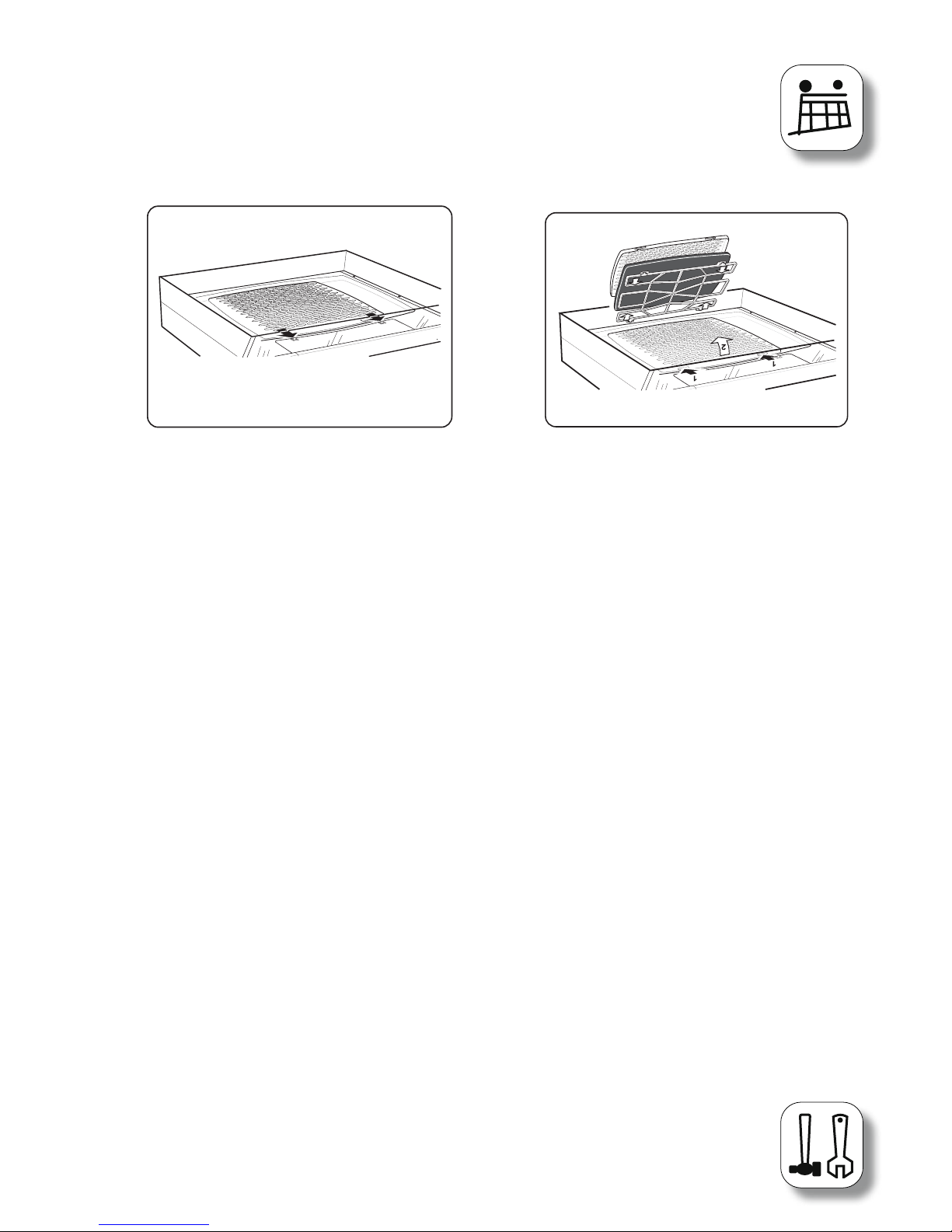
Picture 1
Picture 2
MAINTENANCE OF THE VENTILATION UNIT AND COOKER HOOD
The ventilation unit does not require any mechanical maintenance, only changing of the lters pe-
riodically and cleaning of the heat exchanger and fans (when needed). Cut the power supply to the
unit before starting any service work (from the main switch or by removing the service hatch of the
LTR-series units). Wait for two (2) minutes before starting the maintenance work! Although the unit’s
power supply is cut when the hatch is opened, the fans still rotate and the electrical coil in ECE-model
is still hot for a while.
Cleaning the heat exchanger
When changing the lters, check if the heat exchanger is dirty. If cleaning is required, remove it from
the unit and carefully wash through the air channels with a hand shower using a mild detergent, taking
care not to get the motor wet. The heat exchanger can also be cleaned by blowing through the air chan-
nels using compressed air. Do not use a pressure washer and do not submerge the heat exchanger into
water!! When restarting the unit after cleaning, check that the heat exchanger wheel can turn freely.
Cleaning the fans
When changing lters, also check the condition of the fans. If cleaning is required the fans can be remo-
ved from the unit and cleaned with a toothbrush or compressed air.
Changing of lters
The recommended time between lters changes for the cassette lter and the bag lter is six (6)
months. If class F5 baglters are used the time between lter changes can be prolonged to one (1) year,
by vacuuming the lters on the inside.
Remove the old lter and put in a new one. Vacuum cleaning the inside of the device is recommended
at this point. N.B! Make sure to close the service harch carefully!
Cleaning the cooker hood
The cooker hood is wipe with a damp cloth and washing liquid. The lter should be cleaned twice a
month if the use is normal. Loosen the lter cartridge by push the lock tags in the front edge. Take the
lter apart and remove the lter cloth by loosening the lter holder, picture 1. Soak the lter cloth and
lter holder in warm water mixed with washing liquid. The lter cartridge (with the cloth) can also be
washed in a dish washer. The cooker hood should be cleaned inside some times per year. Wipe the in-
side with a damp cloth and washing liquid. Put the lter cartridge back in place so that it locks in place.
Changing the luminescent lamp in the cooker hood
The lamp glas is loosened by push the lock tags in the direction shown by the arrow, picture 2. The
luminescent lamp is now accessable for change (luminescent lamp socket G23).
Page 36
QUICK GUIDE TO THE VENTILATION UNIT AND
COOKER
GENERAL INFORMATION ABOUT VENTILATION
The basic function of the ventilation unit is to maintain good indoor air quality. When the ventilation is
planned the engineer calculates how big the air amounts need to be in order to get sucient ventila-
tion. The installer species the normal fan speed for the unit when he installes the unit and calibrates
the air ows at every terminal.
VENTILATION DICTIONARY
Outside air The fresh air ow from the outside to the ventilation unit is called outside air.
Supply air The air ow from the ventilation unit to the rooms is called supply air.
Extract air The air ow from the rooms to the ventilation unit is called exhaust air.
Exhaust air The air ow that blows out from the ventilation unit is called waste air.
Heat exchanger The heat exchanger is a component of the ventilation unit that carries heat energy
from the exhaust air ow to the supply air ow. Enervent ventilation units are
equipped with a rotating heat exchanger. The rotating heat exchanger is a wheel
made of thin metal foil, which stores the heat from the exhaust air and carries it to
the supply air. The heat exchanger prevents the warmth from the rooms from
escaping with the waste air ow.
After heating The after heating heats the supply air before it is blown into the rooms. In ECC-
units the after heating is realized with an electrical heater. All units are not equip
ped with after heating.
ECC ECC is the ventilation unit’s control. ECC is an abbreviation of Electronic Climate
Control.
USING THE VENTILATION UNIT
It is very simple to use the ventilation unit. Most of the time it needs no attention. The most important
functions are:
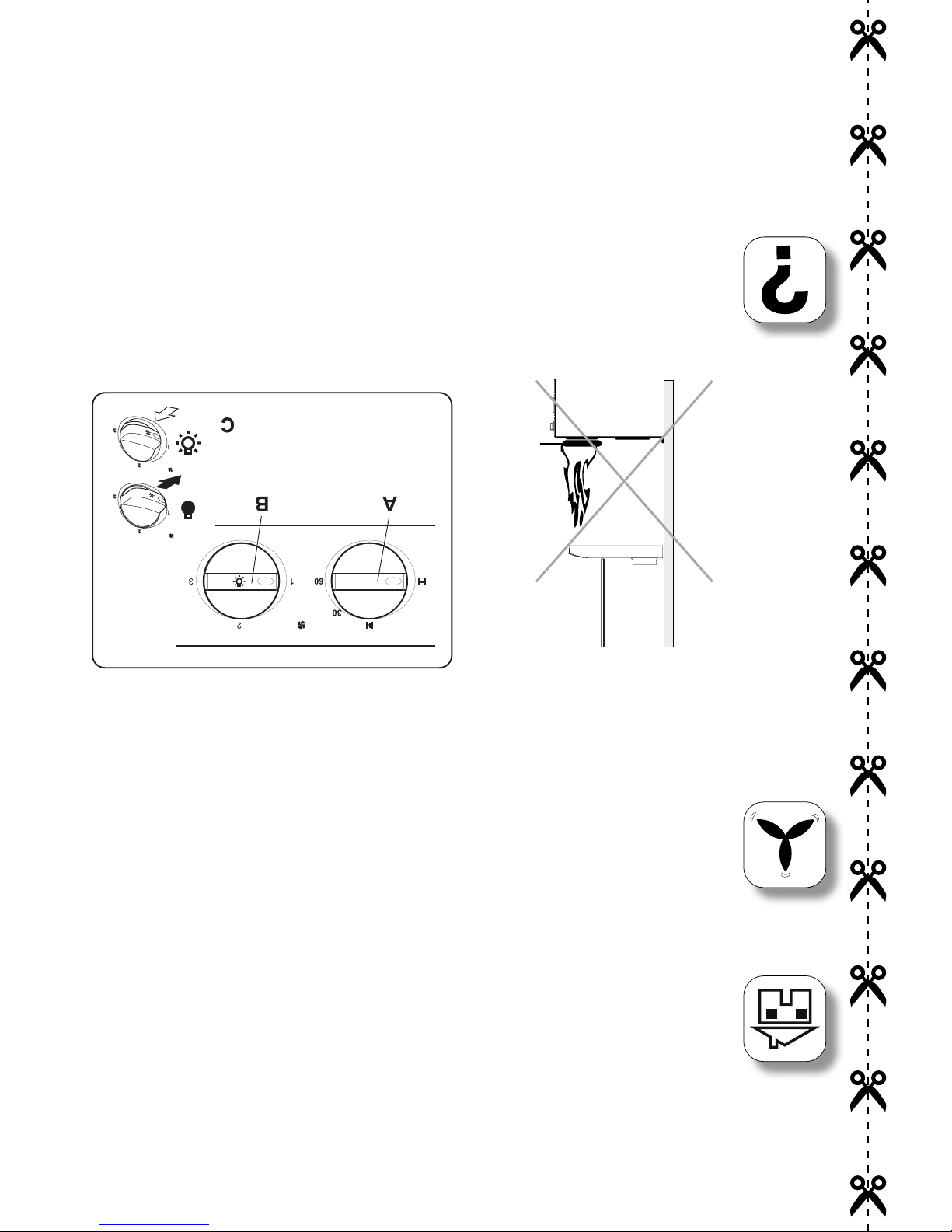
The Piccolo (eco) ECC -unit is controlled with the knobs on the cooker hood front.There is a knob for fan
speeds (B), the damper (A) and the cooker hood light (C).
There are three speeds available; normal speed, which is specied by the installer and on which the
unit runs most of the time; boosting speed which is bigger than the normal speed and is used for
temporary airing and away speed, which is used when nobody is at home.
The damper is opened during cooking (A) and the desired fan speed set (B). The damper shuts auto-
matically after 60 min and the unit resums normal ventilation . Normal ventilation can also be resumed
manually.
NOTE! It is forbidden to ambé under the cooking hood .
 Loading...