

enervent Pegasos HP, Pallas HP, Pelican HP Technical Data And Additional Information To Installation Instructions
Page 1
27.12.2016
Enervent HP
Technical Data and additional
information to Enervent eAir
Installation Instructions
EN
Page 2

2
Page 3

3
Installation manual
EN
Contents
READ ME FIRST ......................................................................................................4
GENERAL ...........................................................................................................4
MAINTENANCE. . . . . . . . . . . . . . . . . . . . . . . . . . . . . . . . . . . . . . . . . . . . . . . . . . . . . . . . . . . . . . . . . . . . . . . . . . . . . . . . . . . . . . . . . . . . . . . . . . . . . .4
TECHNICAL DATA ...................................................................................................5
SERVICE RECORD FOR HEAT PUMP UNIT . . . . . . . . . . . . . . . . . . . . . . . . . . . . . . . . . . . . . . . . . . . . . . . . . . . . . . . . . . . . . . . . . . . . . . . . . . . . .6
WIRING DIAGRAMS . . . . . . . . . . . . . . . . . . . . . . . . . . . . . . . . . . . . . . . . . . . . . . . . . . . . . . . . . . . . . . . . . . . . . . . . . . . . . . . . . . . . . . . . . . . . . . . . .7
CONTROL DIAGRAM . . . . . . . . . . . . . . . . . . . . . . . . . . . . . . . . . . . . . . . . . . . . . . . . . . . . . . . . . . . . . . . . . . . . . . . . . . . . . . . . . . . . . . . . . . . . . . 14
Page 4
4
GENERAL
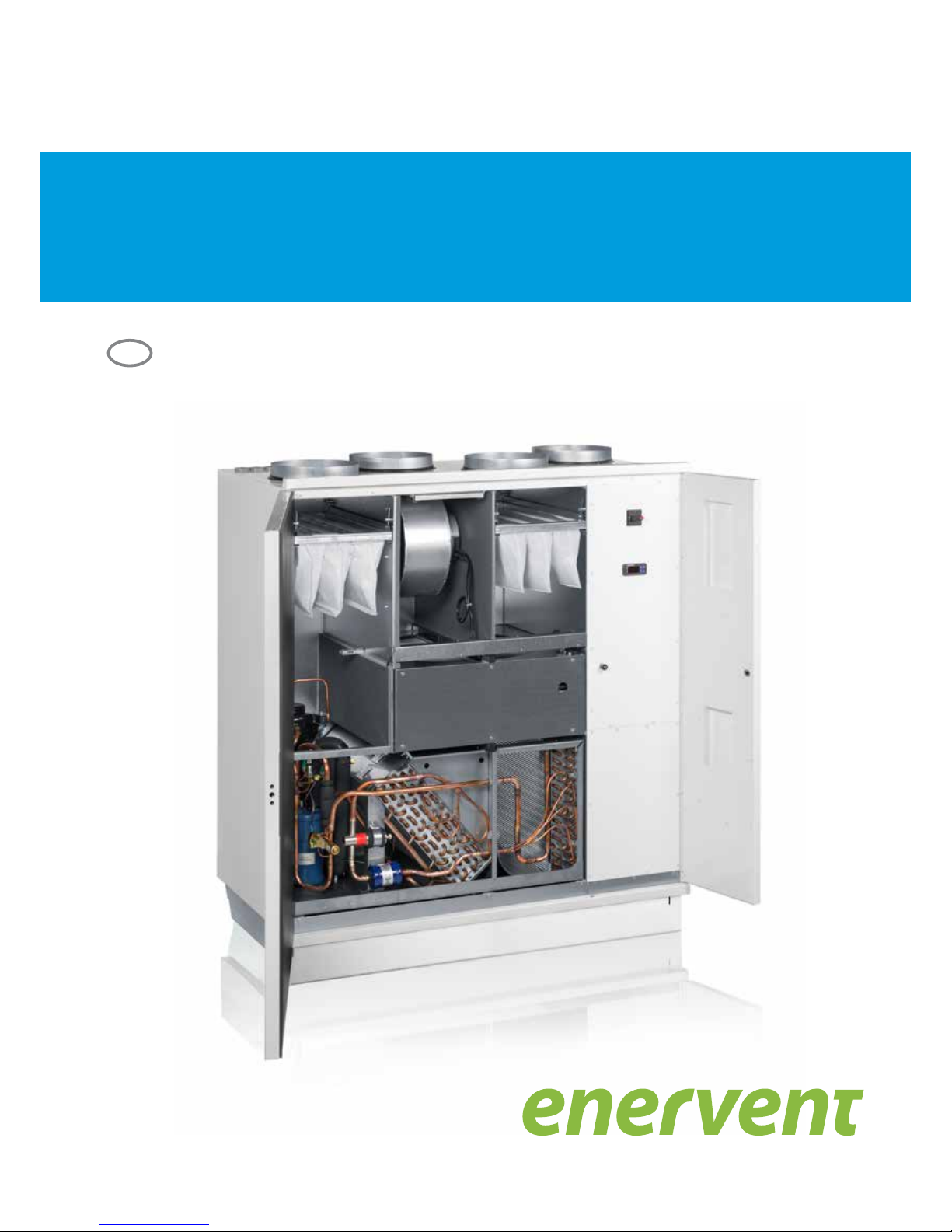
Enervent Pelican HP, Pegasos HP and Pallas HP are
air handling units that consists of (among other
components) a rotating heat recovery wheel and an
extract air heat pump. Units are designed to recover
heat energy from the extract air which is blown out of
the building. Units also cool the supply air depending
the adjustments and circumstances. Units are not
designed to function as a primary heat source of the
building.
NOTE!
NOTE: For the heat pump to work properly the
extract air must be warm enough (extract air to
unit must be at least +20 °C).
Because the integrated extract-air-source heat pump
does not require a separate outdoor unit, it is also
suitable for sites where the installation of outdoor
units is restricted by regulations on façades. The unit
is suitable for both new buildings and renovation
projects.
MAINTENANCE
For maintenance see Enervent eAir Installation
instructions.
NOTE!
NOTE: The heat pump in the ventilation
unit may contain more than 2.39 kg of R410A
HFC refrigerant. The European Union's F-gas
Regulation No 517/2014 states that the
operators of equipment containing more than
2.39 kg of R410A HFC refrigerant are responsible
for maintaining a service record of such
equipment and carry out annual refrigerant
leakage checks by qualied personnel.
NOTE!
NOTE: : Ventilation units equipped with
Emerson© EC3-D73 Digital superheat controller
(concerns Pegasos and Pallas HP units) contains
a VRLA battery= valve regulated rechargeable
lead-acid battery. The battery must NOT be
disposed of with other commercial waste.
Instead, it is the user’s responsibility to pass it
to a designated collection point for the safe
recycling of batteries.
READ ME FIRST
This document is intended for everyone involved
in installation of Enervent ventilation units. The
equipment described in this manual is to be installed
by skilled persons only, according to the instructions
given in this manual, Enervent eAir Installation
Instructions, and local law and regulations. Failure to
comply with instructions in this manual and Enervent
eAir Installation Instructions will void the warranty of
the equipment, and possibly result in harm to people or
property.
The equipment described in this manual is not to be
used by persons (including children) with reduced
physical, sensory or mental capabilities, or lack of
experience and knowledge, unless they have been
given supervision or instruction concerning use of the
equipment by a person responsible for their safety.
NOTE!
NOTE: The Unit must not be tilted more than
45° during transport.
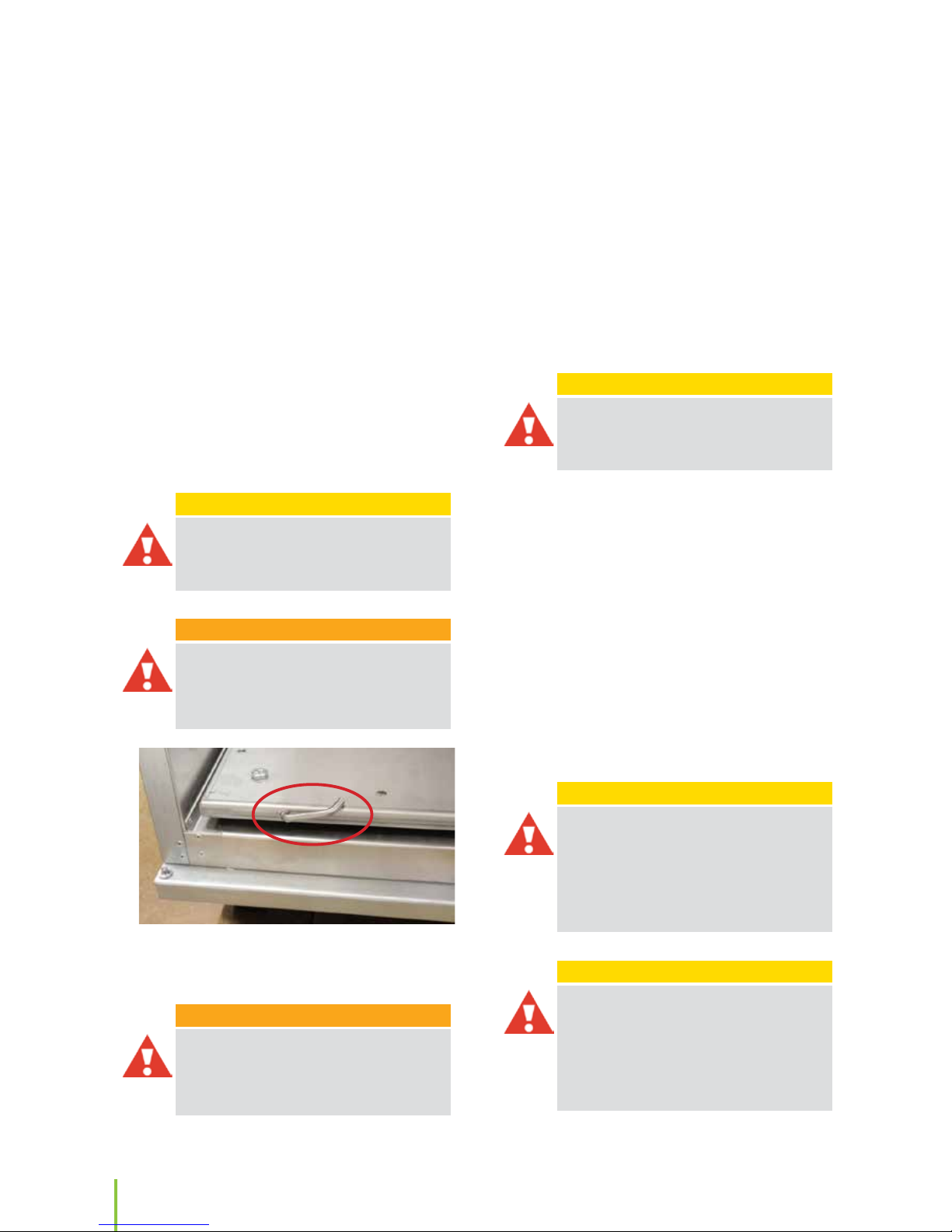
WARNING!
WARNING: Before operating the heat pump
in the Pallas HP models, remove the transport
support for the compressor mounting plate
as indicated in the picture below. Pull the rod
completely out from the compressor mounting
plate to disengage the transport support.
WARNING!
WARNING: Airow calibration must be done
before engaging the heat pump. In Pegasos and
Pallas HP eAir units the heat pump is engaged
from inside the electrical connection box: Circuit
breaker F1.
Page 5

5
Installation manual
EN
TECHNICAL DATA
For technical data see eAir Installation manual except
for following points:
Refrigerant: R410A
Refrigerant charge:
Pelican HP: 1.5 kg
Pegasos HP: 2.3 kg
Pallas HP: 5,2 kg
Compressor´s nominal input power:
Pelican HP: 0,9 kW
Pegasos HP: 4,0 kW
Pallas HP: 5,5 kW
Compressor´s oil type: POE RL32H
Compressor´s oil charge:
Pelican HP: pre-lled by component supplier.
Pegasos HP: 1,2 l
Pallas HP:1,9 l
Netto Weight of the Unit:
Pelican HP: 149,5 kg
Pegasos HP 244,6 kg
Pallas HP: 445,6 kg
Superheating control fuse (F3 Pegasos and F4 Pallas):
T2,5 A
Power supply connection:
Pelican HP: 1 x C16A /230V 1~
Pegasos HP: 3 x C16A /400V 3~
Pallas HP: 3 x C20A /400V 3~
NOTE!
NOTE: Wrong phase order will prevent the heat
pump from operating (Pegasos HP and Pallas HP
only)
Minimum allowed airow when heat pump is in
operation:
Pelican: 104 l/s (375 m³/h)
Pegasos: 120 l/s (432 m³/h)
Pallas: 200 l/s (720 m³/h)
Page 6
6
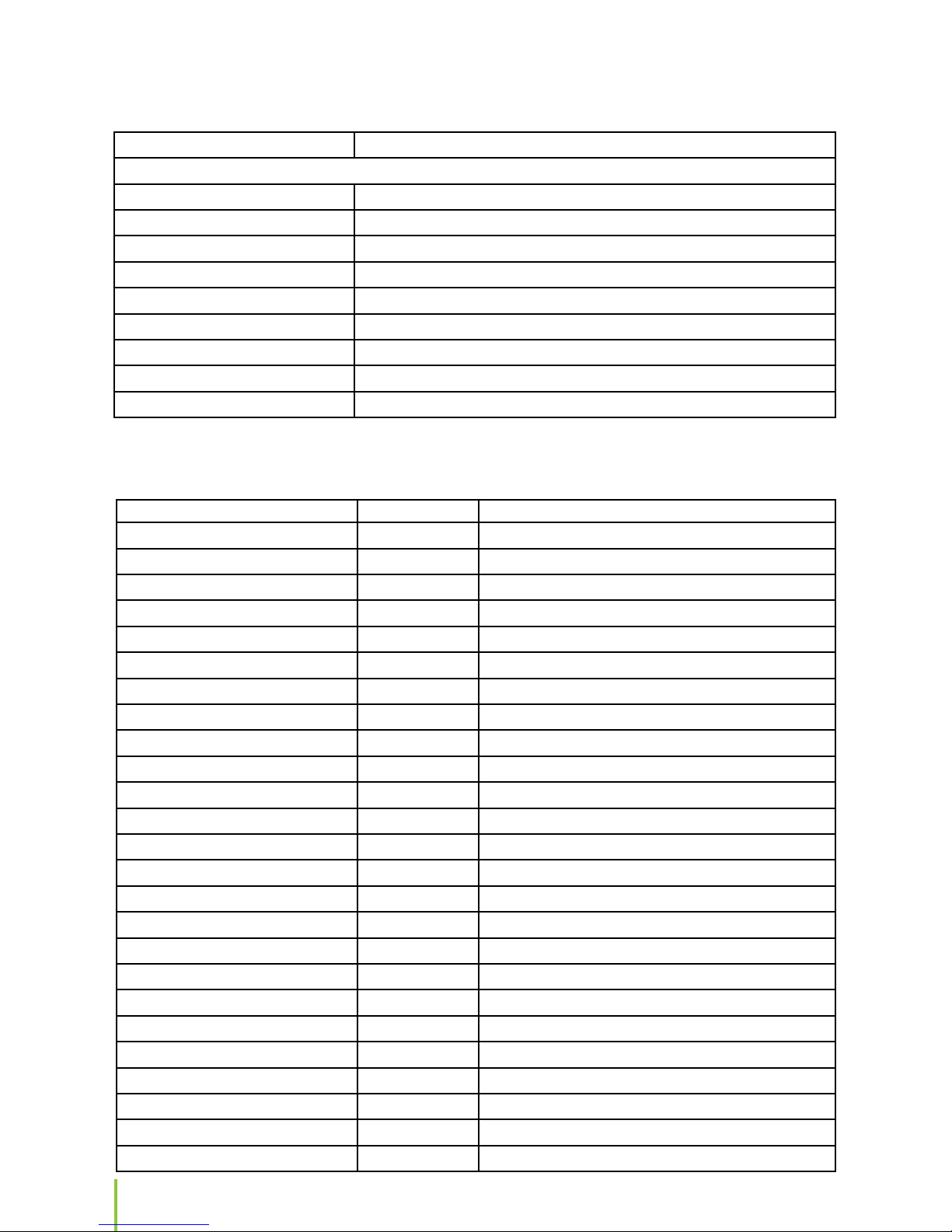
SERVICE RECORD FOR HEAT PUMP UNIT
Owner of the Heat Pump Unit:
Location of the Heat Pump Unit
Street address:
Postal Code:
City:
Country:
Unit system identication:
Unit Model:
Serial Number:
Refrigerant Type
Refrigerant amount:
Test done by: Date: Test passed: accepted/rejected
Annual refrigerant leakage test
Page 7
7
Installation manual
EN
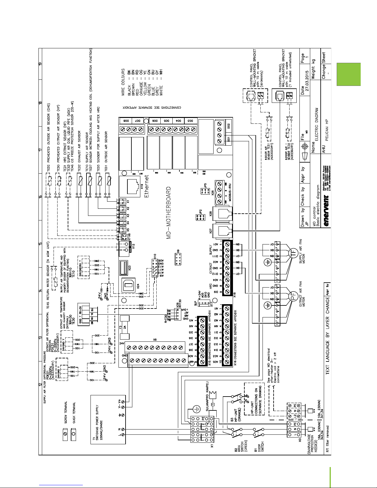
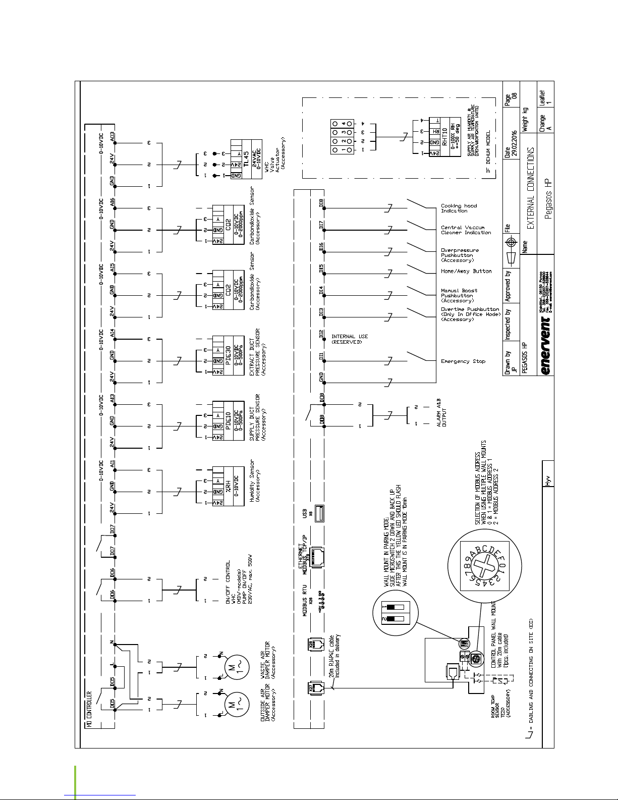
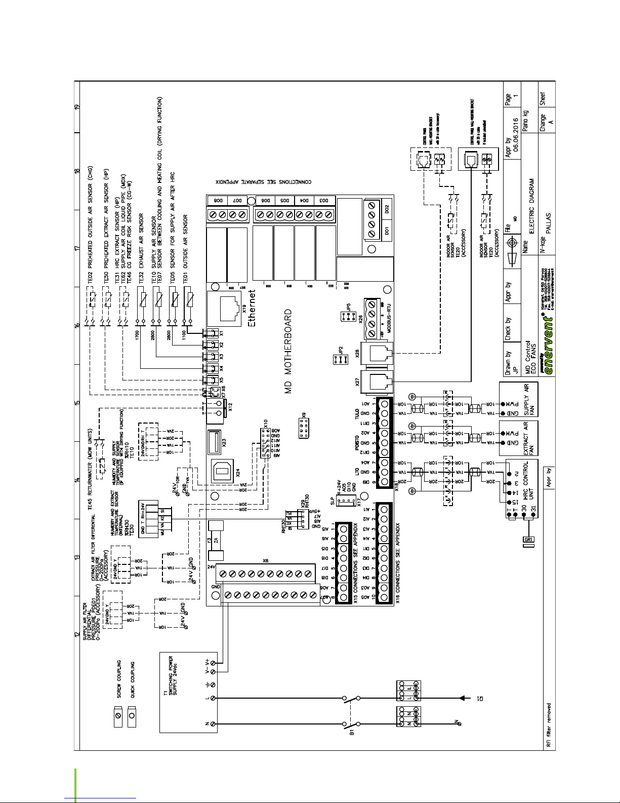
WIRING DIAGRAMS
Page 8
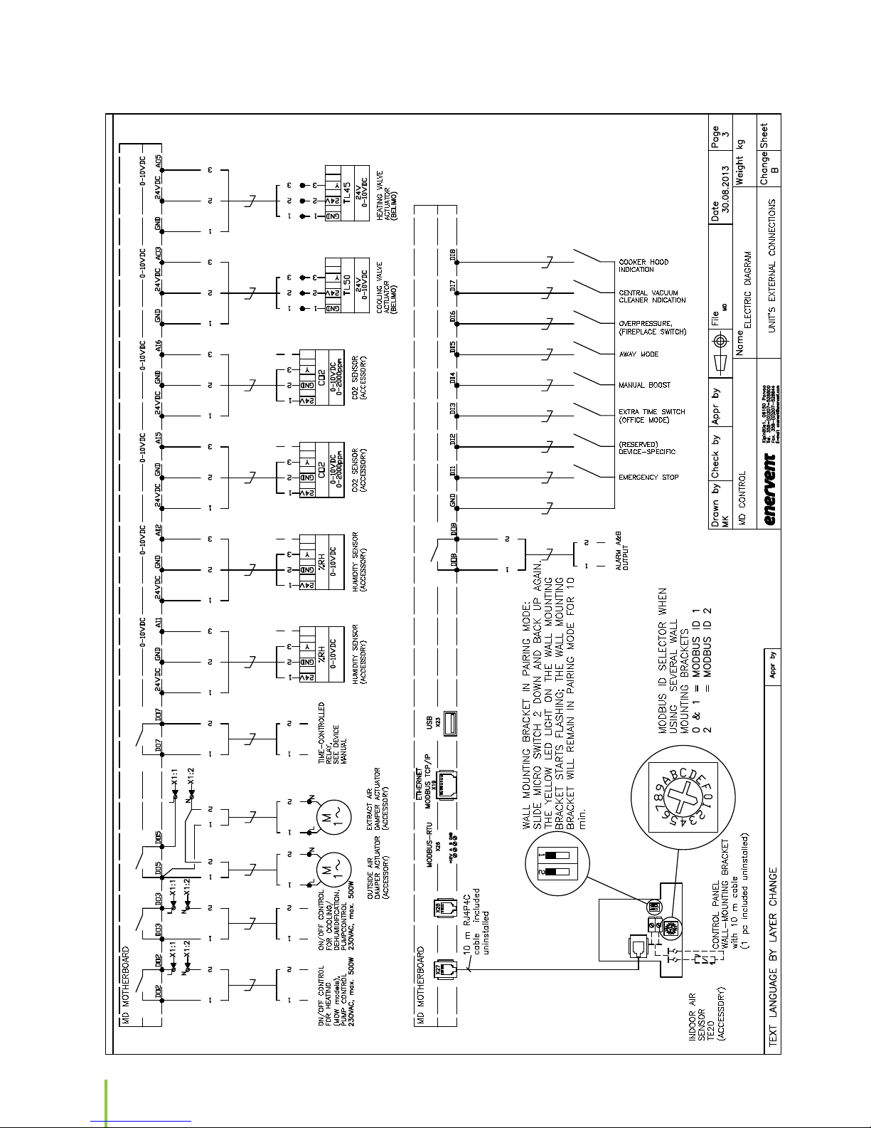
8
Page 9

9
Installation manual
EN
Page 10
10
Page 11

11
Installation manual
EN
Page 12
12
Page 13

13
Installation manual
EN
Page 14

14
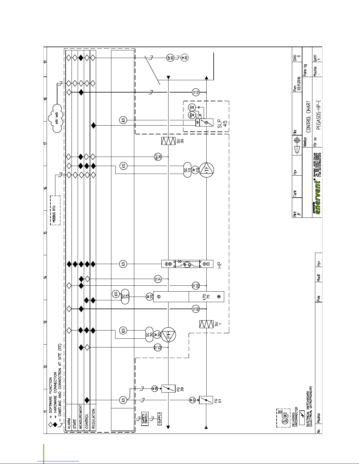
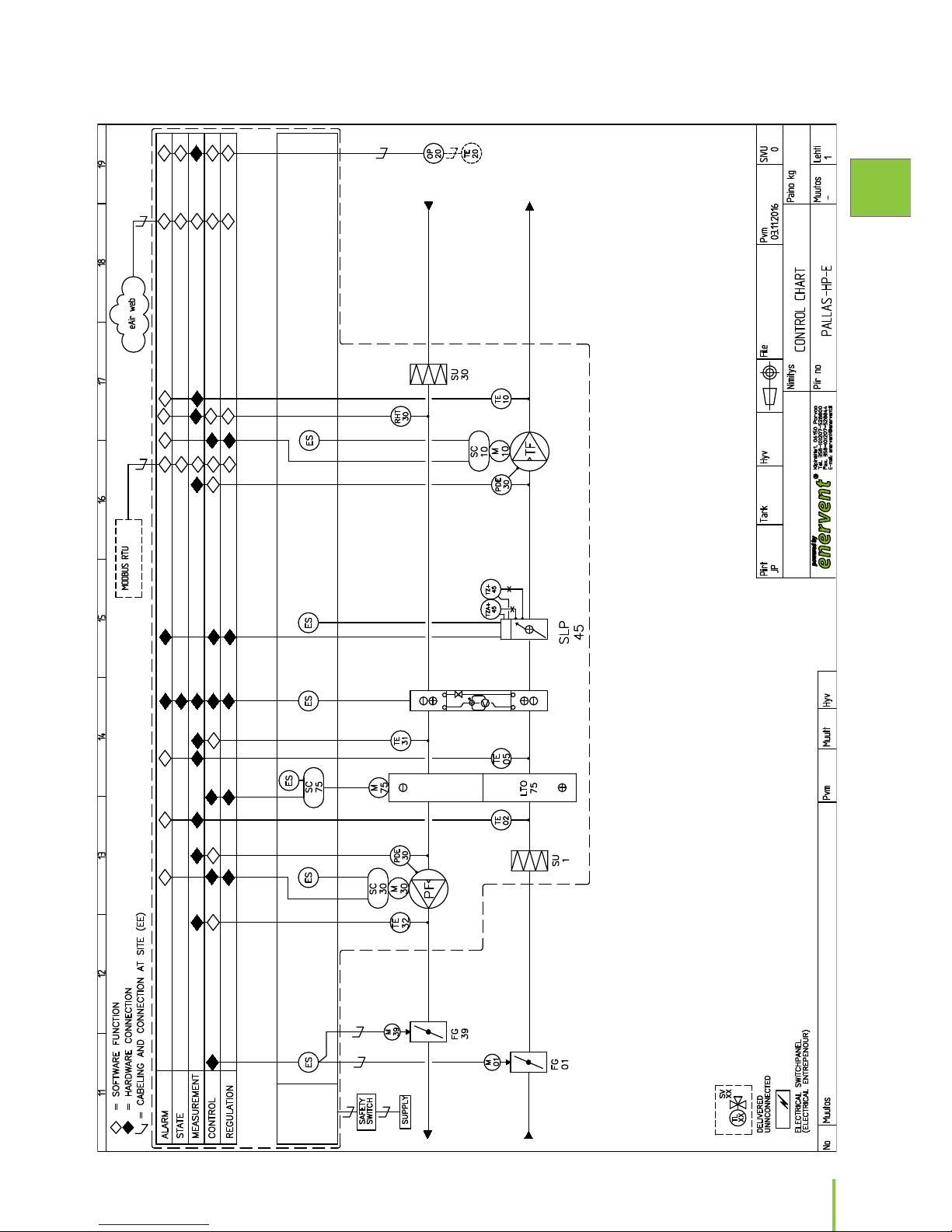
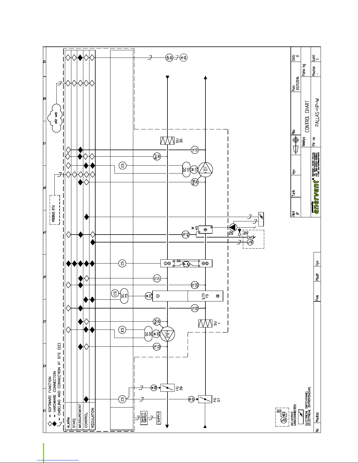
CONTROL DIAGRAM
Page 15

15
Installation manual
EN
MD
ELECTRICAL
CABINET
UNIT
Page 16
16
MD
ELECTRICAL
CABINET
UNIT
Page 17

17
Installation manual
EN
MD
ELECTRICAL
CABINET
UNIT
Page 18

18
ELECTRICAL
CABINET
UNIT
Page 19
19
Installation manual
EN
ELECTRICAL
CABINET
UNIT
Page 20
20
ELECTRICAL
CABINET
UNIT
Page 21

21
Installation manual
EN
Page 22

22
Page 23

23
Installation manual
EN
Page 24

Enervent Oy
Kipinätie 1, FI-06150 PORVOO
Phone: +358 207 528 800
enervent@enervent.com
www.enervent.com
 Loading...