

Page 1

29.11.2017
Enervent Neo
Maintenance, Repair and Recycling manual
Page 2

2
Copyright © Enervent 2017.
Unauthorised copying and distribution is forbidden.
Page 3

3
Maintenance , Repair and Recycling manual
CONTENTS
READ FIRST ................................................................................................................ 4
TYPE PLATE ................................................................................................................ 5
SAFETY .................................................................................................................... 6
General ................................................................................................................ 6
Electrical safety ........................................................................................................ 6
UNIT MAINTENANCE . . . . . . . . . . . . . . . . . . . . . . . . . . . . . . . . . . . . . . . . . . . . . . . . . . . . . . . . . . . . . . . . . . . . . . . . . . . . . . . . . . . . . . . . . . . . . . . . . . . . . . . 7
Opening the lower service hatch . . . . . . . . . . . . . . . . . . . . . . . . . . . . . . . . . . . . . . . . . . . . . . . . . . . . . . . . . . . . . . . . . . . . . . . . . . . . . . . . . . . . . . . 7
Taking the spare belt into use . . . . . . . . . . . . . . . . . . . . . . . . . . . . . . . . . . . . . . . . . . . . . . . . . . . . . . . . . . . . . . . . . . . . . . . . . . . . . . . . . . . . . . . 7
Changing the heat exchanger motor . . . . . . . . . . . . . . . . . . . . . . . . . . . . . . . . . . . . . . . . . . . . . . . . . . . . . . . . . . . . . . . . . . . . . . . . . . . . . . . 8
Dismantling of lower part . . . . . . . . . . . . . . . . . . . . . . . . . . . . . . . . . . . . . . . . . . . . . . . . . . . . . . . . . . . . . . . . . . . . . . . . . . . . . . . . . . . . . . . . . . . . . . 9
Cleaning the heat exchanger . . . . . . . . . . . . . . . . . . . . . . . . . . . . . . . . . . . . . . . . . . . . . . . . . . . . . . . . . . . . . . . . . . . . . . . . . . . . . . . . . . . . . . 10
Changing the heat exchanger drive belt . . . . . . . . . . . . . . . . . . . . . . . . . . . . . . . . . . . . . . . . . . . . . . . . . . . . . . . . . . . . . . . . . . . . . . . . . . . 11
Dismantling of upper part . . . . . . . . . . . . . . . . . . . . . . . . . . . . . . . . . . . . . . . . . . . . . . . . . . . . . . . . . . . . . . . . . . . . . . . . . . . . . . . . . . . . . . . . . . . . . 13
Maintenance of fans and heater element . . . . . . . . . . . . . . . . . . . . . . . . . . . . . . . . . . . . . . . . . . . . . . . . . . . . . . . . . . . . . . . . . . . . . . . . . . . . . . 14
Cleaning of fans . . . . . . . . . . . . . . . . . . . . . . . . . . . . . . . . . . . . . . . . . . . . . . . . . . . . . . . . . . . . . . . . . . . . . . . . . . . . . . . . . . . . . . . . . . . . . . . . . . . 15
TAKING UNIT INTO USE AFTER SERVICE . . . . . . . . . . . . . . . . . . . . . . . . . . . . . . . . . . . . . . . . . . . . . . . . . . . . . . . . . . . . . . . . . . . . . . . . . . . . . . . . . . . . 17
Reassembling the unit . . . . . . . . . . . . . . . . . . . . . . . . . . . . . . . . . . . . . . . . . . . . . . . . . . . . . . . . . . . . . . . . . . . . . . . . . . . . . . . . . . . . . . . . . . . . . . . . 17
APPENDICES ..............................................................................................................22
Troubleshooting ......................................................................................................22
RECYCLING INSTRUCTIONS . . . . . . . . . . . . . . . . . . . . . . . . . . . . . . . . . . . . . . . . . . . . . . . . . . . . . . . . . . . . . . . . . . . . . . . . . . . . . . . . . . . . . . . . . . . . . . . 23
Dimensional drawings . . . . . . . . . . . . . . . . . . . . . . . . . . . . . . . . . . . . . . . . . . . . . . . . . . . . . . . . . . . . . . . . . . . . . . . . . . . . . . . . . . . . . . . . . . . . . . . . 24
Dimensional drawing, left handed . . . . . . . . . . . . . . . . . . . . . . . . . . . . . . . . . . . . . . . . . . . . . . . . . . . . . . . . . . . . . . . . . . . . . . . . . . . . . . . . . 24
Dimensional drawing, right handed . . . . . . . . . . . . . . . . . . . . . . . . . . . . . . . . . . . . . . . . . . . . . . . . . . . . . . . . . . . . . . . . . . . . . . . . . . . . . . . 25
ELECTRICAL DIAGRAMS . . . . . . . . . . . . . . . . . . . . . . . . . . . . . . . . . . . . . . . . . . . . . . . . . . . . . . . . . . . . . . . . . . . . . . . . . . . . . . . . . . . . . . . . . . . . . . 26
External connections . . . . . . . . . . . . . . . . . . . . . . . . . . . . . . . . . . . . . . . . . . . . . . . . . . . . . . . . . . . . . . . . . . . . . . . . . . . . . . . . . . . . . . . . . . . . . . 26
Internal connections . . . . . . . . . . . . . . . . . . . . . . . . . . . . . . . . . . . . . . . . . . . . . . . . . . . . . . . . . . . . . . . . . . . . . . . . . . . . . . . . . . . . . . . . . . . . . . 28
Electrical heater . . . . . . . . . . . . . . . . . . . . . . . . . . . . . . . . . . . . . . . . . . . . . . . . . . . . . . . . . . . . . . . . . . . . . . . . . . . . . . . . . . . . . . . . . . . . . . . . . . . 30
SPARE PARTS LIST . . . . . . . . . . . . . . . . . . . . . . . . . . . . . . . . . . . . . . . . . . . . . . . . . . . . . . . . . . . . . . . . . . . . . . . . . . . . . . . . . . . . . . . . . . . . . . . . . . . . . 31
Page 4

4
READ FIRST
This instruction manual is intended for all people involved
in maintenance and repairing of the Enervent ventilation
units. Only professionally skilled persons may maintain
and repair the equipment described in this manual,
according to the instructions provided in this manual
and to the local laws and regulations. Failure to comply
with the instructions provided in this manual will result in
cancellation of the warranty for the equipment and may
result in harm to people or property.
The equipment described in this manual may not be
used by persons (including children) with reduced
physical, sensory or mental capacity or without sufficient
experience or knowledge, unless a person responsible for
their safety is supervising and advising in the use of the
equipment.
Page 5

5
Maintenance , Repair and Recycling manual
Should you need any technical support, refer to the type
plate for the equipment type and serial number before
contacting support.
Technical support:
www.enervent.com/contact-information/
Webshop for supplies and spareparts:
webshop.enervent.com
Service instructions and service requests:
www.enervent.com/help-center/
TYPE PLATE
ilmanvaihtolaite
ventilation unit
TYYPPI/TYPE:
W/ V/ HZ / A:
www.enervent.com
SRJ. NRO/SERIAL NO:
IP 20
Page 6

6
SAFETY
General Electrical safety
Always check that the equipment supply voltage
is switched off before opening the service hatch.
Only an authorised electrician may perform any
actions in the electrical box.
Follow the local regulations on electrical
installations.
In case of malfunction, always find out the reason
for the malfunction before starting the unit again.
Wait for two (2) minutes after switching off
the power of the unit before commencing the
maintenance. Although the power is switched
off, the fans continue running and the heating
element stays hot for a while.
Check that the unit is entirely isolated from the
mains before conducting any voltage tests,
insulation resistance measurements or other
electrical work or measurements. Such work may
damage the sensitive electrical devices.
Control devices used in the ventilation units may
cause leakage current. It may affect the operation
of the residual current devices.
All ventilation units with a control system must be
equipped with an over-voltage arrester.
DANGER DANGER
DANGER
WARNING
WARNING CAUTION
CAUTION
CAUTION
Page 7
7
Maintenance , Repair and Recycling manual
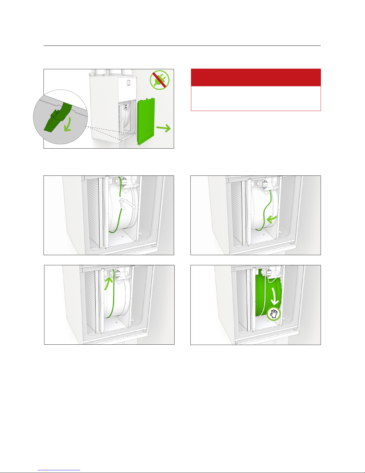
UNIT MAINTENANCE
1
Taking the spare belt into use
Opening the lower service hatch
2
4
1
3
Always check that the equipment supply voltage
is switched off before opening the service hatch.
DANGER
Page 8
8
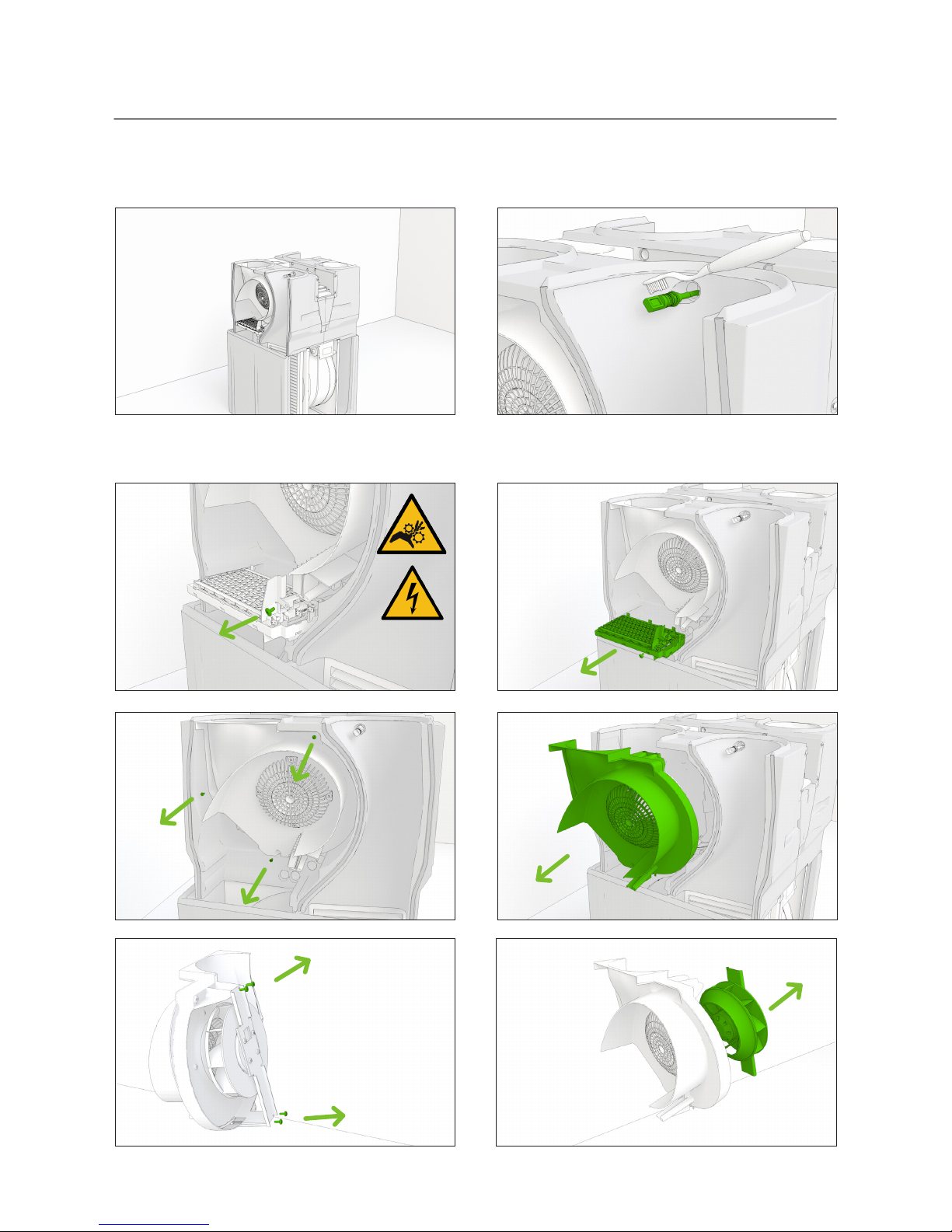
Changing the heat exchanger motor
2
4
1
3
Page 9

9
Maintenance , Repair and Recycling manual
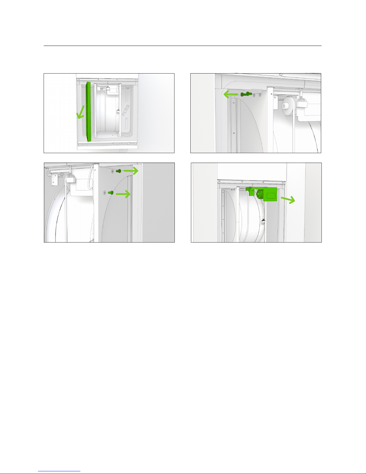
Always check that the equipment supply voltage
is switched off before opening the service hatch.
Dismantling of lower part
Before dismantling the lower part, open the lower service hatch, see page 7 picture 1.
3
1 2
4
5b
5a
6a 6b
DANGER
Page 10
10
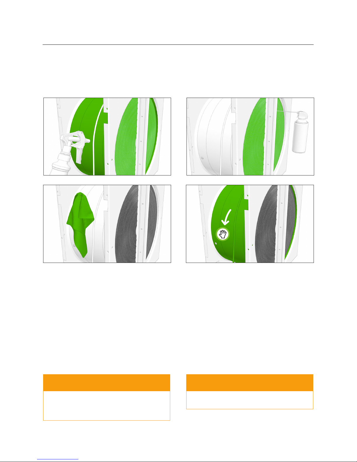
2
3
4
1
Check the cleanliness of the rotating heat exchanger visually when changing filters, and clean it if it looks dirty. Before
cleaning the heat exchanger, see. "Dismantling of lower part" on page. 9. The cleaning is to be performed by an authorized
service provider.
Cleaning the heat exchanger
Do not submerge the heat exchanger in water.The
electric motor inside the heat exchanger must not
get wet.
The use of a pressure washer is strictly forbidden.
WARNING WARNING
Page 11
11
Maintenance , Repair and Recycling manual
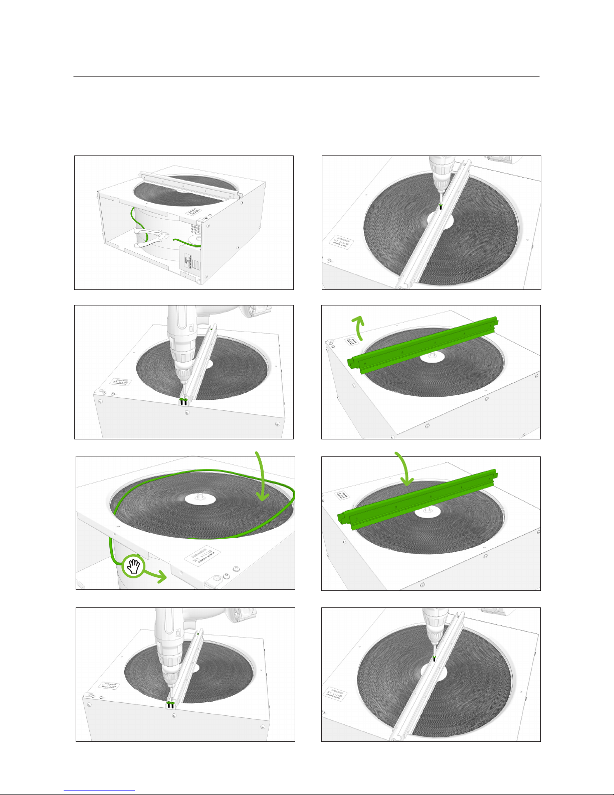
Changing the heat exchanger drive belt
5
3
1
2
4
Before changing the belt, see. "Dismantling of lower part" on page. 9.
7
6
8
Page 12

12
10
9
11
12
13
14
Page 13

13
Maintenance , Repair and Recycling manual
Dismantling of upper part
5 6
Always check that the equipment supply voltage
is switched off before opening the service hatch.
DANGER
Only an authorized service provider may dismantle the unit
1
3 4
2
Å power cord
7
Å external sensors
Page 14

14
Maintenance of fans and heater element
Look first. "Dismantling of lower part" on page. 9..
1
2a 2b
3 4
Page 15
15
Maintenance , Repair and Recycling manual
Supply air fan
1
1
3
2
2
Cleaning of fans
4
65
Page 16

16
43
7
5
Extract air fan
1 2
Page 17

17
Maintenance , Repair and Recycling manual
TAKING UNIT INTO USE AFTER SERVICE
2
3a 3b
4
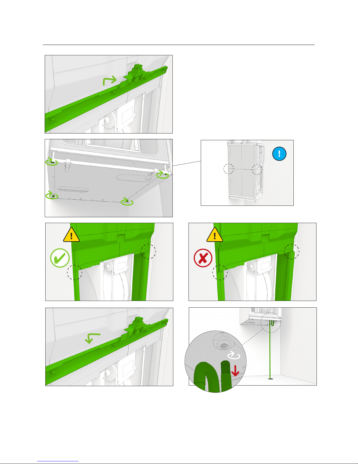
Reassembling the unit
1
5
7
Å power cord
6
Å external sensors
silicone
Page 18

18
11 12
13
14
+2 mm 0 mm
10b10a
8
9
push all the way in 20 mm
22 mm
5 mm at a time
Page 19
19
Maintenance , Repair and Recycling manual
18
19
0 mm
0 mm
15
16
17b17a
Page 20

20
24
23
22
20
21
Page 21

21
Maintenance , Repair and Recycling manual
Page 22

22
Troubleshooting
APPENDICES
Alarm Description
Alarm
limit
Symptoms Possible cause Action Notes
FILS Service
reminder.
4 or 6
months
It is time for regular maintenance. Replace the filters.
Inspect the ventilation unit.
Clean as necessary.
See if there are any damages
visible.
Acknowledge by
pressing any button
for 5 seconds.
Err Sensor
malfunction.
The sensor is in short circuit or
there is an interruption in the
circuit.
Check the connections and
cables of the sensors.
- - - - Downloading. The eWind panel downloads
data from the motherboard.
Normal during start-up. In
other situations, check the
eWind connection cable.
oFFE Stop mode. Ventilation off. External control system has
switched the ventilation unit to
stop mode.
AL1 Water heat-
ing coil is in
danger of
freezing.
+8 °C Cold supply air. The water coil is frozen/about to
freeze:
• The circulation pump has
stopped.
• The heat exchanger does not
rotate.
• The control valve actuator of
the water coil is faulty.
• The extract fan has stopped.
Restart the pump.
Replace the motor or the
belt.
Replace the actuator.
Find out the reason/replace
the fan.
The unit will not
start until the alarm
mode is cleared and
the alarm reset by
pressing a button in
the operation panel.
AL2 The supply
air is cold
after the
rotating heat
exchanger.
+5 °C Cold supply air. The heat exchanger does not
rotate:
• The drive belt is damaged.
• The drive belt skids.
• The heat exchanger motor is
damaged.
Replace the drive belt.
Clean or replace the belt or
the heat exchanger.
Replace the heat exchanger
motor.
The ventilation
unit switches to
malfunction mode,
in which the fans
operate with minimum power.
The alarm is automatically reset
when the fault is
cleared.
AL3 Cold supply
air.
+10 °C Cold supply air. The extract fan has stopped. Replace the fan.
The extract filter is clogged. Replace the filter.
The ventilation is adjusted incor-
rectly/not adjusted at all.
Adjust the ventilation as per
the ventilation system plan
with appropriate measurement tools.
The heat insulation of the ducts is
insufficient.
Check the insulation thickness of the supply and
extract air ducts and add
insulation as necessary.
The fan speed of the ventilation
unit is incorrect.
Always use a fan speed
specified by the ventilation unit designer (also in
winter).
AL4 Supply fan
malfunction.
No ventilation. The supply fan has stopped. Repair or replace the supply
fan.
The unit will not
start until the alarm
mode is cleared and
the alarm is reset by
pressing a button in
the operation panel.
AL5 Extract fan
malfunction.
No ventilation The extract fan has stopped. Repair or replace the extract
fan.
Page 23

23
Maintenance , Repair and Recycling manual
RECYCLING INSTRUCTIONS
Check the recycling instructions regarding the end-of-life of the unit on the webpage www.enervent.com.
Alarm Description
Alarm
limit
Symptoms Possible cause Action Notes
AL6 Cold extract
air.
+10 °C Cold supply air. Low indoor temperature. Raise the indoor
temperature.
Acknowledge by
pressing any button
for 5 seconds.
Insufficient heat insulation of the
extract air duct.
Check the insulation of the
ducts and add insulation as
necessary.
The ventilation unit’s service
hatch is open.
Close the service hatch
Temperature sensor TE30 is faulty. Repair or replace the sensor.
AL7 Hot supply
air.
Fire hazard.
+55 °C Hot supply air. Fire hazard. Check if there are any heat
sources.
The device will not
start until the alarm
mode is cleared and
the ventilation unit
started again.
There is a malfunction in the
electric after-heating coil.
Repair or replace the electric
after-heating coil.
There is a malfunction in the
actuator of the water-based afterheating coil’s valve.
Repair or replace the valve’s
actuator.
Temperature sensor TE10 is faulty. Repair or replace the tem-
perature sensor.
AL8 Overheating
of the electric
after-heating
or preheat
coil.
Hot supply air. Electric preheat or after-heating
coil does not work:
• Overheating protector has
tripped.
• The supply fan has stopped.
• The supply air filter is clogged.
• The outside air grille is
clogged.
• The heater controller board is
damaged.
• The heater is damaged.
Find out the reason for
overheating and reset the
error message.
Find out the reason/replace
the fan.
Replace the filter.
Clean the grille. Remove any
mosquito net.
Replace the controller
board.
Replace the heater
AL9 Hot extract
air.
Fire hazard.
+55 °C Hot extract air. Fire hazard.
Temperature sensor TE30 is faulty.
Check if there are any heat
sources.
Repair or replace the temperature sensor.
Page 24
24
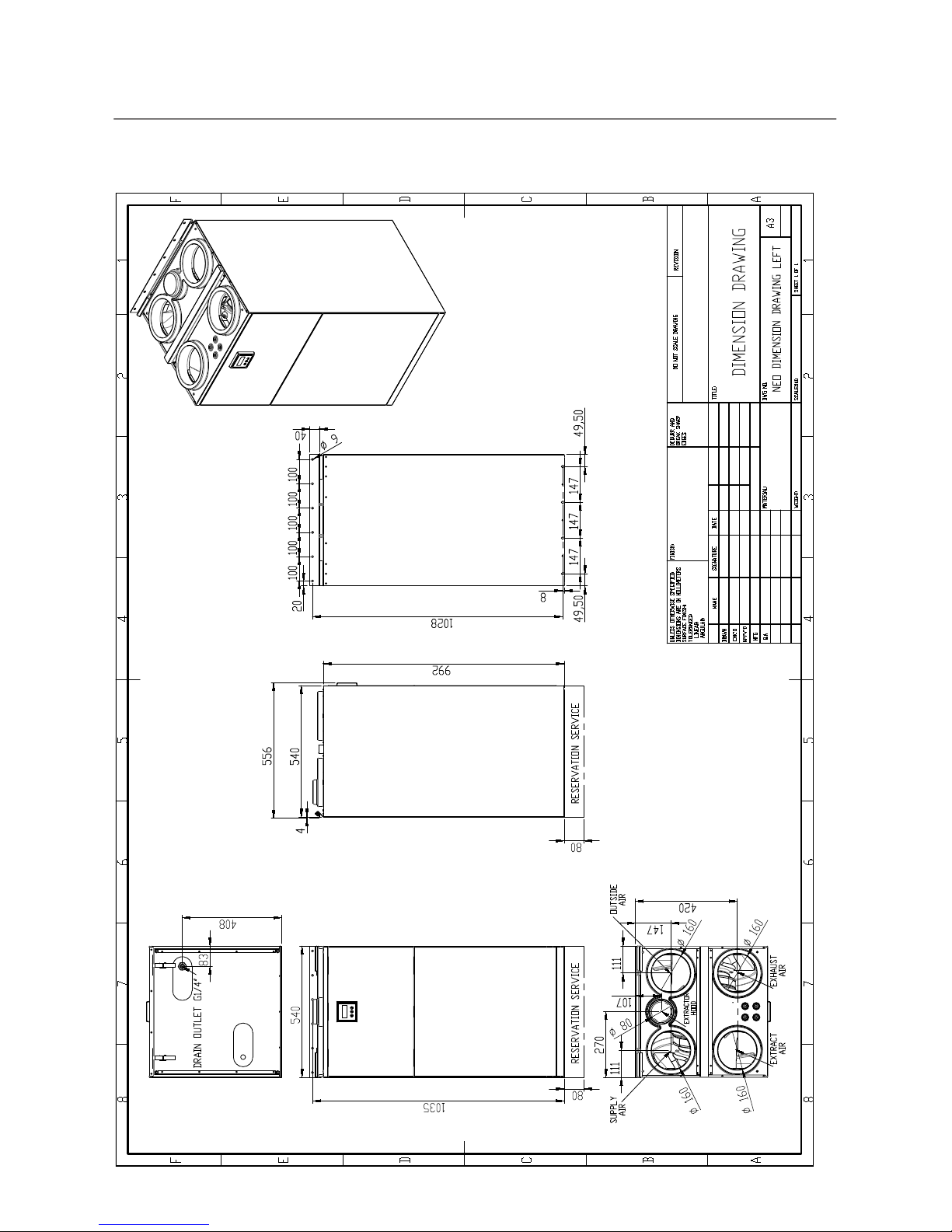
Dimensional drawings
Dimensional drawing, left handed
Page 25

25
Maintenance , Repair and Recycling manual
Dimensional drawing, right handed
Page 26
26
Electrical diagrams
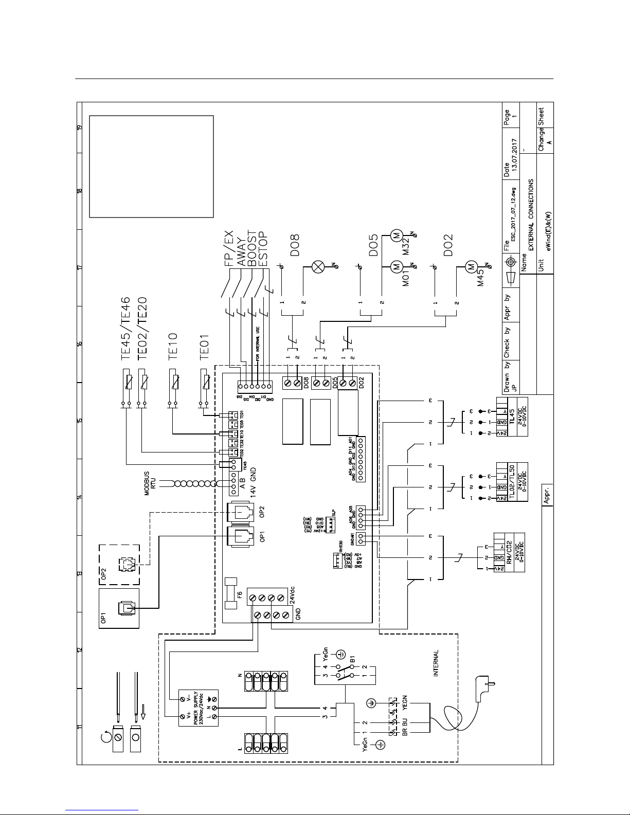
External connections
WIRE COLOURS
BK BLACK
BN BROWN
RD RED
OG ORANGE
YE YELLOW
GN GREEN
BU BLUE
GY GREY
WH WHITE
Page 27

27
Maintenance , Repair and Recycling manual
Name Explanation Marking on circuit board
FP/EX
FIREPLACE/EXTRACTOR HOOD MODE
DI6
AWAY AWAY MODE DI5
BOOST MANUAL BOOST DI4
ESTOP EXTERNAL STOP DI1
TE45
RETURNWATER TEMPERATURE SENSOR eWind W UNITS
TE45
TE46
RETURNWATER TEMPERATURE SENSOR eWind CG UNITS
TE45
TE02
PREHEATED OUTSIDE AIR TEMPERATURE, EXTERNAL PREHEATER
TE02
TE20
RECIRCULATION AIR TEMPERATURE (KOTILÄMPÖ eWind)
TE02
TE10 SUPPLY AIR TEMPERATURE TE10
TE01 OUTSIDE AIR TEMPERATURE TE01
RH CO²
EXTERNAL HUMIDITY SENSOR (RH 0-100%) BY DEFAULT IF PARAMETER c27 IS ACTIVE, CO² SENSOR
(200-2000ppm) (ACCESSORY)
AI1
TL01
TL50
PREHEATER VALVE ACTUATOR -CHG MODELS COOLING VALVE ACTUATOR -CG MODELS
AO6
TL45
HEATING VALVE ACTUATOR -W MODELS
AO5
DO8 ALARM A OUTPUT BY DEFAULT PREHEATER ON/OFF CONTROL IN -CHG -AGH -ELECTRICAL
PREHEATER MODELS COOLING ON/OFF CONTROL IN -CG MODELS
DO8
DO5 OUTSIDE AIR AND EXHAUST AIR DAMPER CONTROL (ACCESSORY) DO5
DO2 HEATING ON/OFF CONTROL eWind W MODELS MAX 500W PUMP DO2
OP1 USERPANEL 1pcs. INCLUDED IN DELIVERY, 10m CABLE INCLUDED IF NOT MOUNTED ON UNIT OP1
OP2 USERPANEL (ACCESSORY) 10m CABLE INCLUDED IN DELIVERY OP2
Page 28

28
Internal connections
WIRE COLOURS
BK BLACK
BN BROWN
RD RED
OG ORANGE
YE YELLOW
GN GREEN
BU BLUE
GY GREY
WH WHITE
Page 29

29
Maintenance , Repair and Recycling manual
Name Explanation Marking on circuit board
TE45
RETURN WATER SENSOR eWind W UNITS
TE45
TE46
RETURN WATER SENSOR eWind CG UNITS
TE45
TE02
PREHEATED OUTSIDE AIR SENSOR
TE02
TE20
RETURN AIR TEMPERATURE (KOTILÄMPÖ eWind UNITS)
TE02
TE32
EXHAUST AIR TEMPERATURE SENSOR
TE32
TE10
SUPPLY AIR TEMPERATURE SENSOR
TE10
TE05
AIR TEMPERATURE AFTER THE HEAT RECOVERY HEAT EXCHANGER
TE05
TE01
OUTSIDE AIR TEMPERATURE SENSOR
TE01
RHT30
EXTRACT AIR TEMPERATURE AND HUMIDITY SENSOR(RH 0-100%)
RHT30
SF10 SUPPLY AIR FAN AO1,DI11
EF30 EXTRACT AIR FAN AO2,DI12
CF20
RETURN AIR FAN (KOTILÄMPÖ UNITS ONLY)
AO6
M75
HEAT RECOVERY HEAT EXCHANGER MOTOR
AO4
Page 30
30
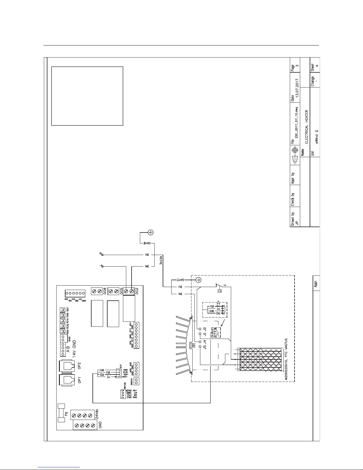
Electrical heater
WIRE COLOURS
BK BLACK
BN BROWN
RD RED
OG ORANGE
YE YELLOW
GN GREEN
BU BLUE
GY GREY
WH WHITE
Page 31
31
Maintenance , Repair and Recycling manual
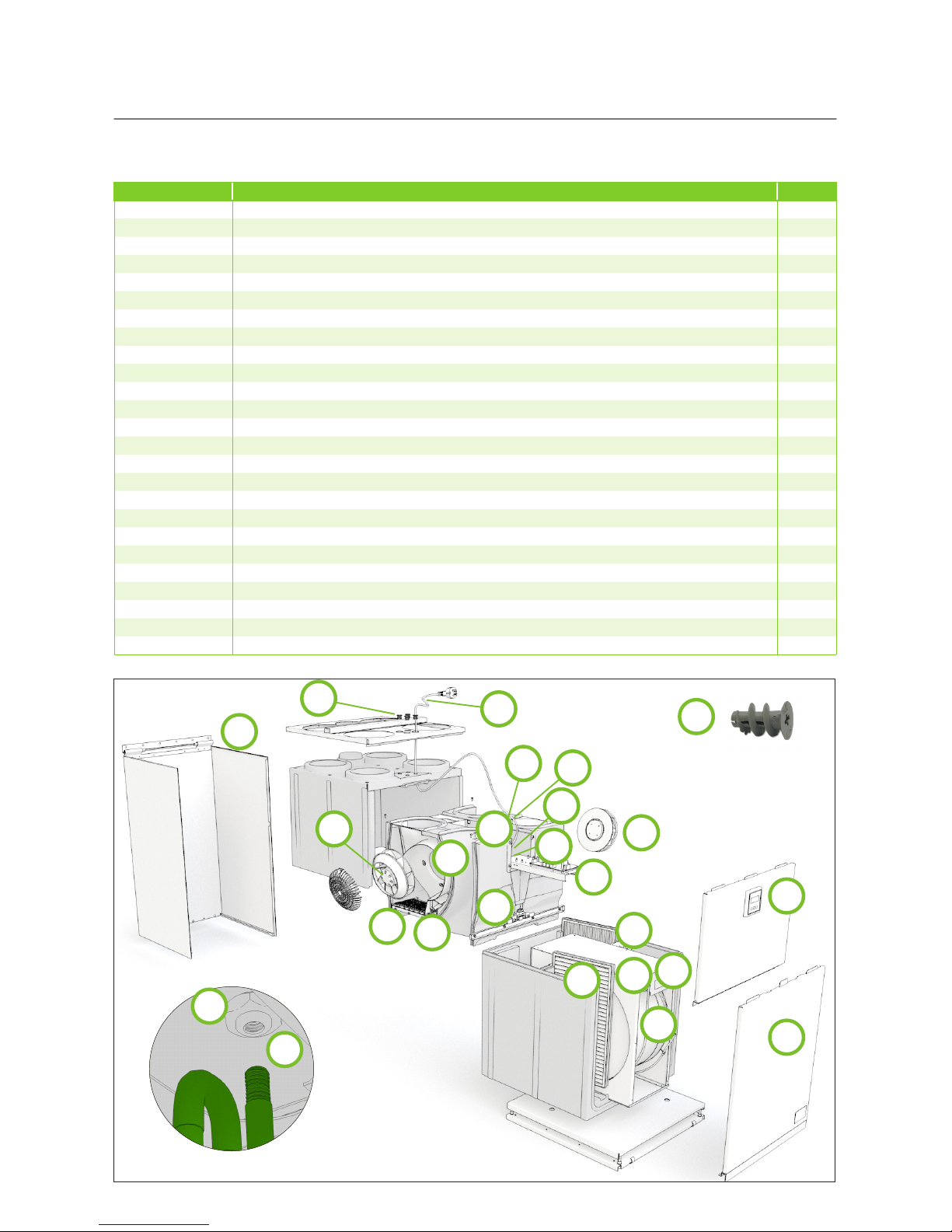
Product number Product name
K030160001 Neo Door 1
M070100200 Sealing strip O-sealing with fastening D=7,5 464128300 2
K930040220 Neo bulkhead door EPP 3
M900500301 52389 GK plastic plug Fischer 4
M480500015 Rubber grommet EV16 5-10 5
M360500030 Sink strainer / kondensation drain P160010501A NEO 6
M900100009 Nut DIN 934/8 ZN M20 7
K100160002 Rotating heat exchanger, stepless drive Neo 8
M140030016 Belt, PUW green,1440mm/6mm Neo 9
K120160003 Rotor motor package, stepless DC Neo 10
K140160001 Fan package, supply Neo 11
K140160002 Fan package, extract Neo 12
M680010040 Power cord 1,5m 3x1,5 including Molex and grommet 13
M710910001 eWind motherboard 14
M230110602 Humidity/temperature sensor Amphenol 600mm T9602-5-A-0.60-EV cable and connector 15
M620200011 Tufvassons switch mode power supply PSLR 24 16
M120200007 Control circuit board EM-240-M1 DC-motor 17
M230120604 EDA temperature sensor 850mm 2-nap NTC 10K sensor 850 2-pol con 18
M230120602 EDA temperature sensor 500mm 2-nap NTC 10K sensor 500 2-pol con 19
K160163001 Electrical heater Neo eWind E 20
M710600007 EDA electrical heater control circuit board Enerpoint 21
K580040003 eWind control panel Neo Package includes operating panel and 350mm cable 22
M210190142 Exchange filters F7/M5 (supply/extract) Unit size Neo 23
M03P160010022 Wall mounting bracket 24
M490300002 Switch, FA1CA22 Door switch 25
Spare parts list
Left handed
1
3
9
6
10
7
12
18
15
25
11
16
19
13
22
23
20
21
14
2
8
4
17
24
5
Page 32

Enervent Oy
Kipinätie 1
FIN-06150 Porvoo, Finland
Tel. +358 207 528 800
Fax. +358 207 528 844
enervent@enervent.com
www.enervent.com
 Loading...