

Page 1

Enervent eWind
12.7.2017
ENG
Installation instruction
Page 2

Copyright © Enervent 2017.
Unauthorized copying and lending are prohibited.
Approvals and version history
Revision Date Description of change Approved by
0.0 2016-01-25
1.0 2017-07-12
2
Page 3

Contents
Approvals and version history . . . . . . . . . . . . . . . . . . . . . . . . . . . . . . . . . . . . . . . . . . . . . . . . . . . . . . . . . . . . . . . . . . . . . . . . . . . . . . . . . . . . . . .2
READ ME FIRST ......................................................................................................6
Type plate .......................................................................................................6
Type designation . . . . . . . . . . . . . . . . . . . . . . . . . . . . . . . . . . . . . . . . . . . . . . . . . . . . . . . . . . . . . . . . . . . . . . . . . . . . . . . . . . . . . . . . . . . . . . . .6
SAFETY .............................................................................................................7
General .........................................................................................................7
Electrical ........................................................................................................7
TERMINOLOGY ......................................................................................................8
BEFORE INSTALLATION . . . . . . . . . . . . . . . . . . . . . . . . . . . . . . . . . . . . . . . . . . . . . . . . . . . . . . . . . . . . . . . . . . . . . . . . . . . . . . . . . . . . . . . . . . . . . .9
Selecting installation location . . . . . . . . . . . . . . . . . . . . . . . . . . . . . . . . . . . . . . . . . . . . . . . . . . . . . . . . . . . . . . . . . . . . . . . . . . . . . . . . . . . .9
Pinion, Pingvin, Pingvin XL, Pandion, Pelican, Pegasos and Pegasos XL 9
LTR-2, LTR-3, LTR-4, LTR-6, LTR-7 and LTR-7 XL . . . . . . . . . . . . . . . . . . . . . . . . . . . . . . . . . . . . . . . . . . . . . . . . . . . . . . . . . . . . . . . . . .9
BUILDING THE VENTILATION SYSTEM . . . . . . . . . . . . . . . . . . . . . . . . . . . . . . . . . . . . . . . . . . . . . . . . . . . . . . . . . . . . . . . . . . . . . . . . . . . . . . 10
Insulating ventilation ducts . . . . . . . . . . . . . . . . . . . . . . . . . . . . . . . . . . . . . . . . . . . . . . . . . . . . . . . . . . . . . . . . . . . . . . . . . . . . . . . . . . . . 11
Ventilation duct insulation examples . . . . . . . . . . . . . . . . . . . . . . . . . . . . . . . . . . . . . . . . . . . . . . . . . . . . . . . . . . . . . . . . . . . . . . . . . . . 11
Outside air duct (fresh air duct) . . . . . . . . . . . . . . . . . . . . . . . . . . . . . . . . . . . . . . . . . . . . . . . . . . . . . . . . . . . . . . . . . . . . . . . . . . . . . 11
Supply air duct . . . . . . . . . . . . . . . . . . . . . . . . . . . . . . . . . . . . . . . . . . . . . . . . . . . . . . . . . . . . . . . . . . . . . . . . . . . . . . . . . . . . . . . . . . . . . 11
Extract air duct . . . . . . . . . . . . . . . . . . . . . . . . . . . . . . . . . . . . . . . . . . . . . . . . . . . . . . . . . . . . . . . . . . . . . . . . . . . . . . . . . . . . . . . . . . . . . 12
Exhaust air duct . . . . . . . . . . . . . . . . . . . . . . . . . . . . . . . . . . . . . . . . . . . . . . . . . . . . . . . . . . . . . . . . . . . . . . . . . . . . . . . . . . . . . . . . . . . . 12
Extractor hood duct . . . . . . . . . . . . . . . . . . . . . . . . . . . . . . . . . . . . . . . . . . . . . . . . . . . . . . . . . . . . . . . . . . . . . . . . . . . . . . . . . . . . . . . . 12
Installing duct coils . . . . . . . . . . . . . . . . . . . . . . . . . . . . . . . . . . . . . . . . . . . . . . . . . . . . . . . . . . . . . . . . . . . . . . . . . . . . . . . . . . . . . . . . . . . . 12
Duct coil for uids . . . . . . . . . . . . . . . . . . . . . . . . . . . . . . . . . . . . . . . . . . . . . . . . . . . . . . . . . . . . . . . . . . . . . . . . . . . . . . . . . . . . . . . . . . 12
Electrical duct coils . . . . . . . . . . . . . . . . . . . . . . . . . . . . . . . . . . . . . . . . . . . . . . . . . . . . . . . . . . . . . . . . . . . . . . . . . . . . . . . . . . . . . . . . . 13
Installing ventilation unit ceiling installation plate (OPTIONAL) 13
Installing geo-cooling equipment . . . . . . . . . . . . . . . . . . . . . . . . . . . . . . . . . . . . . . . . . . . . . . . . . . . . . . . . . . . . . . . . . . . . . . . . . . . . . . 14
Option 1 (standard) . . . . . . . . . . . . . . . . . . . . . . . . . . . . . . . . . . . . . . . . . . . . . . . . . . . . . . . . . . . . . . . . . . . . . . . . . . . . . . . . . . . . . . . . 14
Option 2 ...................................................................................................14
Installing geothermal CHG pre-heating / pre-cooling equipment . . . . . . . . . . . . . . . . . . . . . . . . . . . . . . . . . . . . . . . . . . . . . . . 15
Option 1 ...................................................................................................15
Option 2 ...................................................................................................15
ELECTRICAL CONNECTIONS . . . . . . . . . . . . . . . . . . . . . . . . . . . . . . . . . . . . . . . . . . . . . . . . . . . . . . . . . . . . . . . . . . . . . . . . . . . . . . . . . . . . . . . 17
Preparing for electrical installations . . . . . . . . . . . . . . . . . . . . . . . . . . . . . . . . . . . . . . . . . . . . . . . . . . . . . . . . . . . . . . . . . . . . . . . . . . . . 17
eWind card connections . . . . . . . . . . . . . . . . . . . . . . . . . . . . . . . . . . . . . . . . . . . . . . . . . . . . . . . . . . . . . . . . . . . . . . . . . . . . . . . . . . . . . . . 17
External sensors ............................................................................................... 18
Installing eWind control panel . . . . . . . . . . . . . . . . . . . . . . . . . . . . . . . . . . . . . . . . . . . . . . . . . . . . . . . . . . . . . . . . . . . . . . . . . . . . . . . . . 18
Installing one control panel . . . . . . . . . . . . . . . . . . . . . . . . . . . . . . . . . . . . . . . . . . . . . . . . . . . . . . . . . . . . . . . . . . . . . . . . . . . . . . . . . 18
Installing two control panels . . . . . . . . . . . . . . . . . . . . . . . . . . . . . . . . . . . . . . . . . . . . . . . . . . . . . . . . . . . . . . . . . . . . . . . . . . . . . . . . 18
Installing with Modbus . . . . . . . . . . . . . . . . . . . . . . . . . . . . . . . . . . . . . . . . . . . . . . . . . . . . . . . . . . . . . . . . . . . . . . . . . . . . . . . . . . . . . 18
INSTALLATION ....................................................................................................19
Additional installation materials . . . . . . . . . . . . . . . . . . . . . . . . . . . . . . . . . . . . . . . . . . . . . . . . . . . . . . . . . . . . . . . . . . . . . . . . . . . . . . . . 19
Installing models Pinion, Pingvin, Pingvin XL, Pandion, Pelican, Pegasos and Pegasos XL 20
Wall installation . . . . . . . . . . . . . . . . . . . . . . . . . . . . . . . . . . . . . . . . . . . . . . . . . . . . . . . . . . . . . . . . . . . . . . . . . . . . . . . . . . . . . . . . . . . . 20
Ceiling installation . . . . . . . . . . . . . . . . . . . . . . . . . . . . . . . . . . . . . . . . . . . . . . . . . . . . . . . . . . . . . . . . . . . . . . . . . . . . . . . . . . . . . . . . . 20
Floor installation . . . . . . . . . . . . . . . . . . . . . . . . . . . . . . . . . . . . . . . . . . . . . . . . . . . . . . . . . . . . . . . . . . . . . . . . . . . . . . . . . . . . . . . . . . . 22
Installing models LTR-2, LTR-3, LTR-4, LTR-6, LTR-7 and LTR-7 XL . . . . . . . . . . . . . . . . . . . . . . . . . . . . . . . . . . . . . . . . . . . . . . . . . . 22
Installing model eWind W . . . . . . . . . . . . . . . . . . . . . . . . . . . . . . . . . . . . . . . . . . . . . . . . . . . . . . . . . . . . . . . . . . . . . . . . . . . . . . . . . . . . . . 22
Draining condensate water . . . . . . . . . . . . . . . . . . . . . . . . . . . . . . . . . . . . . . . . . . . . . . . . . . . . . . . . . . . . . . . . . . . . . . . . . . . . . . . . . . . . 23
EN
3Installation instructions
Page 4

COMMISSIONING .................................................................................................25
Requirements .................................................................................................25
Calibrating airow . . . . . . . . . . . . . . . . . . . . . . . . . . . . . . . . . . . . . . . . . . . . . . . . . . . . . . . . . . . . . . . . . . . . . . . . . . . . . . . . . . . . . . . . . . . . . 25
Commissioning checklist . . . . . . . . . . . . . . . . . . . . . . . . . . . . . . . . . . . . . . . . . . . . . . . . . . . . . . . . . . . . . . . . . . . . . . . . . . . . . . . . . . . . . . 25
Control system, eWind operating panel . . . . . . . . . . . . . . . . . . . . . . . . . . . . . . . . . . . . . . . . . . . . . . . . . . . . . . . . . . . . . . . . . . . . . . . . . . . . 26
Important to know about control system . . . . . . . . . . . . . . . . . . . . . . . . . . . . . . . . . . . . . . . . . . . . . . . . . . . . . . . . . . . . . . . . . . . 26
Setting up fan speeds . . . . . . . . . . . . . . . . . . . . . . . . . . . . . . . . . . . . . . . . . . . . . . . . . . . . . . . . . . . . . . . . . . . . . . . . . . . . . . . . . . . . . . 26
Parameter list . . . . . . . . . . . . . . . . . . . . . . . . . . . . . . . . . . . . . . . . . . . . . . . . . . . . . . . . . . . . . . . . . . . . . . . . . . . . . . . . . . . . . . . . . . . . . . 27
Information view . . . . . . . . . . . . . . . . . . . . . . . . . . . . . . . . . . . . . . . . . . . . . . . . . . . . . . . . . . . . . . . . . . . . . . . . . . . . . . . . . . . . . . . . . . . . . . 28
eWind Info list . . . . . . . . . . . . . . . . . . . . . . . . . . . . . . . . . . . . . . . . . . . . . . . . . . . . . . . . . . . . . . . . . . . . . . . . . . . . . . . . . . . . . . . . . . . . . . 28
Measurements view . . . . . . . . . . . . . . . . . . . . . . . . . . . . . . . . . . . . . . . . . . . . . . . . . . . . . . . . . . . . . . . . . . . . . . . . . . . . . . . . . . . . . . . . . . . 29
eWind Measurements list . . . . . . . . . . . . . . . . . . . . . . . . . . . . . . . . . . . . . . . . . . . . . . . . . . . . . . . . . . . . . . . . . . . . . . . . . . . . . . . . . . . 29
Documenting commissioning . . . . . . . . . . . . . . . . . . . . . . . . . . . . . . . . . . . . . . . . . . . . . . . . . . . . . . . . . . . . . . . . . . . . . . . . . . . . . . . . . . 29
USING THE EQUIPMENT . . . . . . . . . . . . . . . . . . . . . . . . . . . . . . . . . . . . . . . . . . . . . . . . . . . . . . . . . . . . . . . . . . . . . . . . . . . . . . . . . . . . . . . . . . 30
General .......................................................................................................30
Fans ...........................................................................................................30
CO (accessory) and humidity boosting of fans. . . . . . . . . . . . . . . . . . . . . . . . . . . . . . . . . . . . . . . . . . . . . . . . . . . . . . . . . . . . . . . . . . 30
Fireplace / extractor hood mode . . . . . . . . . . . . . . . . . . . . . . . . . . . . . . . . . . . . . . . . . . . . . . . . . . . . . . . . . . . . . . . . . . . . . . . . . . . . . . . 31
Manual boosting . . . . . . . . . . . . . . . . . . . . . . . . . . . . . . . . . . . . . . . . . . . . . . . . . . . . . . . . . . . . . . . . . . . . . . . . . . . . . . . . . . . . . . . . . . . . . . 31
Temperature control . . . . . . . . . . . . . . . . . . . . . . . . . . . . . . . . . . . . . . . . . . . . . . . . . . . . . . . . . . . . . . . . . . . . . . . . . . . . . . . . . . . . . . . . . . . 31
Heat recovery . . . . . . . . . . . . . . . . . . . . . . . . . . . . . . . . . . . . . . . . . . . . . . . . . . . . . . . . . . . . . . . . . . . . . . . . . . . . . . . . . . . . . . . . . . . . . . 31
Cooling recovery . . . . . . . . . . . . . . . . . . . . . . . . . . . . . . . . . . . . . . . . . . . . . . . . . . . . . . . . . . . . . . . . . . . . . . . . . . . . . . . . . . . . . . . . . . . 31
Heat recovery anti-freezing . . . . . . . . . . . . . . . . . . . . . . . . . . . . . . . . . . . . . . . . . . . . . . . . . . . . . . . . . . . . . . . . . . . . . . . . . . . . . . . . . 31
Heat recovery eciency . . . . . . . . . . . . . . . . . . . . . . . . . . . . . . . . . . . . . . . . . . . . . . . . . . . . . . . . . . . . . . . . . . . . . . . . . . . . . . . . . . . . 31
Alarms ........................................................................................................31
MAINTENANCE. . . . . . . . . . . . . . . . . . . . . . . . . . . . . . . . . . . . . . . . . . . . . . . . . . . . . . . . . . . . . . . . . . . . . . . . . . . . . . . . . . . . . . . . . . . . . . . . . . . . 32
Service reminder . . . . . . . . . . . . . . . . . . . . . . . . . . . . . . . . . . . . . . . . . . . . . . . . . . . . . . . . . . . . . . . . . . . . . . . . . . . . . . . . . . . . . . . . . . . . . . 32
Filters ......................................................................................................... 32
Filter types ................................................................................................. 32
Replacing lters . . . . . . . . . . . . . . . . . . . . . . . . . . . . . . . . . . . . . . . . . . . . . . . . . . . . . . . . . . . . . . . . . . . . . . . . . . . . . . . . . . . . . . . . . . . . 33
Fans ...........................................................................................................34
Inspecting .................................................................................................34
Cleaning ................................................................................................... 34
Heat exchanger. . . . . . . . . . . . . . . . . . . . . . . . . . . . . . . . . . . . . . . . . . . . . . . . . . . . . . . . . . . . . . . . . . . . . . . . . . . . . . . . . . . . . . . . . . . . . . . . 34
Inspecting .................................................................................................34
Cleaning ................................................................................................... 34
Replacing heat exchanger belt . . . . . . . . . . . . . . . . . . . . . . . . . . . . . . . . . . . . . . . . . . . . . . . . . . . . . . . . . . . . . . . . . . . . . . . . . . . . . . 34
TECHNICAL INFORMATION AND ATTACHMENTS . . . . . . . . . . . . . . . . . . . . . . . . . . . . . . . . . . . . . . . . . . . . . . . . . . . . . . . . . . . . . . . . . . . . 36
Models with duct coils . . . . . . . . . . . . . . . . . . . . . . . . . . . . . . . . . . . . . . . . . . . . . . . . . . . . . . . . . . . . . . . . . . . . . . . . . . . . . . . . . . . . . . . . . 36
CHG Pre-heating and pre-cooling coils . . . . . . . . . . . . . . . . . . . . . . . . . . . . . . . . . . . . . . . . . . . . . . . . . . . . . . . . . . . . . . . . . . . . . . . . . 37
CHG Left-handed coil . . . . . . . . . . . . . . . . . . . . . . . . . . . . . . . . . . . . . . . . . . . . . . . . . . . . . . . . . . . . . . . . . . . . . . . . . . . . . . . . . . . . . . . 38
CHG Right-handed coil . . . . . . . . . . . . . . . . . . . . . . . . . . . . . . . . . . . . . . . . . . . . . . . . . . . . . . . . . . . . . . . . . . . . . . . . . . . . . . . . . . . . . 38
List of extra equipment . . . . . . . . . . . . . . . . . . . . . . . . . . . . . . . . . . . . . . . . . . . . . . . . . . . . . . . . . . . . . . . . . . . . . . . . . . . . . . . . . . . . . . . . 39
Troubleshooting . . . . . . . . . . . . . . . . . . . . . . . . . . . . . . . . . . . . . . . . . . . . . . . . . . . . . . . . . . . . . . . . . . . . . . . . . . . . . . . . . . . . . . . . . . . . . . . 40
Models and components . . . . . . . . . . . . . . . . . . . . . . . . . . . . . . . . . . . . . . . . . . . . . . . . . . . . . . . . . . . . . . . . . . . . . . . . . . . . . . . . . . . . . . 42
Technical features . . . . . . . . . . . . . . . . . . . . . . . . . . . . . . . . . . . . . . . . . . . . . . . . . . . . . . . . . . . . . . . . . . . . . . . . . . . . . . . . . . . . . . . . . . . . . 44
Dimensional drawings . . . . . . . . . . . . . . . . . . . . . . . . . . . . . . . . . . . . . . . . . . . . . . . . . . . . . . . . . . . . . . . . . . . . . . . . . . . . . . . . . . . . . . . . . 48
Pinion right hand. . . . . . . . . . . . . . . . . . . . . . . . . . . . . . . . . . . . . . . . . . . . . . . . . . . . . . . . . . . . . . . . . . . . . . . . . . . . . . . . . . . . . . . . . . . 48
Pinion left hand . . . . . . . . . . . . . . . . . . . . . . . . . . . . . . . . . . . . . . . . . . . . . . . . . . . . . . . . . . . . . . . . . . . . . . . . . . . . . . . . . . . . . . . . . . . . 49
4
Page 5

Pingvin right hand . . . . . . . . . . . . . . . . . . . . . . . . . . . . . . . . . . . . . . . . . . . . . . . . . . . . . . . . . . . . . . . . . . . . . . . . . . . . . . . . . . . . . . . . . 50
Pingvin left hand . . . . . . . . . . . . . . . . . . . . . . . . . . . . . . . . . . . . . . . . . . . . . . . . . . . . . . . . . . . . . . . . . . . . . . . . . . . . . . . . . . . . . . . . . . . 51
Pingvin XL right hand . . . . . . . . . . . . . . . . . . . . . . . . . . . . . . . . . . . . . . . . . . . . . . . . . . . . . . . . . . . . . . . . . . . . . . . . . . . . . . . . . . . . . . 52
Pingvin XL left hand . . . . . . . . . . . . . . . . . . . . . . . . . . . . . . . . . . . . . . . . . . . . . . . . . . . . . . . . . . . . . . . . . . . . . . . . . . . . . . . . . . . . . . . . 53
Pandion ....................................................................................................54
Pelican ..................................................................................................... 55
Pegasos .................................................................................................... 56
LTR 2 ....................................................................................................... 57
LTR 3 ....................................................................................................... 58
LTR 4 ....................................................................................................... 59
LTR 6 25 mm ............................................................................................... 60
LTR 6 50 mm ............................................................................................... 61
LTR 7 ....................................................................................................... 62
Wiring digrams ................................................................................................63
eWind basic wiring diagram . . . . . . . . . . . . . . . . . . . . . . . . . . . . . . . . . . . . . . . . . . . . . . . . . . . . . . . . . . . . . . . . . . . . . . . . . . . . . . . . 63
eWind basic wiring diagram Pingvin XL, Pegasos (XL) and LTR-7 (XL) 64
eWind basic external connections . . . . . . . . . . . . . . . . . . . . . . . . . . . . . . . . . . . . . . . . . . . . . . . . . . . . . . . . . . . . . . . . . . . . . . . . . . 65
eWind basic internal connections . . . . . . . . . . . . . . . . . . . . . . . . . . . . . . . . . . . . . . . . . . . . . . . . . . . . . . . . . . . . . . . . . . . . . . . . . . . 66
eWind electrical heater ≤ 2kW . . . . . . . . . . . . . . . . . . . . . . . . . . . . . . . . . . . . . . . . . . . . . . . . . . . . . . . . . . . . . . . . . . . . . . . . . . . . . . 67
eWind electrical heater > 2kW . . . . . . . . . . . . . . . . . . . . . . . . . . . . . . . . . . . . . . . . . . . . . . . . . . . . . . . . . . . . . . . . . . . . . . . . . . . . . . 68
eWind external electrical heater . . . . . . . . . . . . . . . . . . . . . . . . . . . . . . . . . . . . . . . . . . . . . . . . . . . . . . . . . . . . . . . . . . . . . . . . . . . . 69
eWind electrical pre-heater . . . . . . . . . . . . . . . . . . . . . . . . . . . . . . . . . . . . . . . . . . . . . . . . . . . . . . . . . . . . . . . . . . . . . . . . . . . . . . . . . 70
eWind extractor hood connections . . . . . . . . . . . . . . . . . . . . . . . . . . . . . . . . . . . . . . . . . . . . . . . . . . . . . . . . . . . . . . . . . . . . . . . . . 71
Principal diagrams . . . . . . . . . . . . . . . . . . . . . . . . . . . . . . . . . . . . . . . . . . . . . . . . . . . . . . . . . . . . . . . . . . . . . . . . . . . . . . . . . . . . . . . . . . . . . 72
eWind HW .................................................................................................72
eWind CG principle scheme 1 . . . . . . . . . . . . . . . . . . . . . . . . . . . . . . . . . . . . . . . . . . . . . . . . . . . . . . . . . . . . . . . . . . . . . . . . . . . . . . . 73
eWind CG principle scheme 2 . . . . . . . . . . . . . . . . . . . . . . . . . . . . . . . . . . . . . . . . . . . . . . . . . . . . . . . . . . . . . . . . . . . . . . . . . . . . . . . 74
eWind CG principle scheme 3 . . . . . . . . . . . . . . . . . . . . . . . . . . . . . . . . . . . . . . . . . . . . . . . . . . . . . . . . . . . . . . . . . . . . . . . . . . . . . . . 75
eWind CG principle scheme 4 . . . . . . . . . . . . . . . . . . . . . . . . . . . . . . . . . . . . . . . . . . . . . . . . . . . . . . . . . . . . . . . . . . . . . . . . . . . . . . . 76
eWind CG principle scheme 5 . . . . . . . . . . . . . . . . . . . . . . . . . . . . . . . . . . . . . . . . . . . . . . . . . . . . . . . . . . . . . . . . . . . . . . . . . . . . . . . 77
eWind CG connections . . . . . . . . . . . . . . . . . . . . . . . . . . . . . . . . . . . . . . . . . . . . . . . . . . . . . . . . . . . . . . . . . . . . . . . . . . . . . . . . . . . . . 78
eWind CHG principle scheme ground loop . . . . . . . . . . . . . . . . . . . . . . . . . . . . . . . . . . . . . . . . . . . . . . . . . . . . . . . . . . . . . . . . . . 79
eWind CHG principle scheme heat exchanger . . . . . . . . . . . . . . . . . . . . . . . . . . . . . . . . . . . . . . . . . . . . . . . . . . . . . . . . . . . . . . . 80
eWind CW principle scheme . . . . . . . . . . . . . . . . . . . . . . . . . . . . . . . . . . . . . . . . . . . . . . . . . . . . . . . . . . . . . . . . . . . . . . . . . . . . . . . . 81
Control Charts ................................................................................................. 82
eWind control charts component catalog . . . . . . . . . . . . . . . . . . . . . . . . . . . . . . . . . . . . . . . . . . . . . . . . . . . . . . . . . . . . . . . . . . . 82
eWind E (ARCTIC) . . . . . . . . . . . . . . . . . . . . . . . . . . . . . . . . . . . . . . . . . . . . . . . . . . . . . . . . . . . . . . . . . . . . . . . . . . . . . . . . . . . . . . . . . . 83
eWind W Pingvin, Pingvin (XL), LTR-3 . . . . . . . . . . . . . . . . . . . . . . . . . . . . . . . . . . . . . . . . . . . . . . . . . . . . . . . . . . . . . . . . . . . . . . . . 84
eWind W Pandion, Pelican, Pegasos, Pegasos XL, LTR-2, LTR-4, LTR-6, LTR-7, LTR-7 XL 85
eWind E-CG Pingvin XL, Pegasos XL, LTR-3, LTR-7, LTR-7 XL . . . . . . . . . . . . . . . . . . . . . . . . . . . . . . . . . . . . . . . . . . . . . . . . . . . 86
eWind E-CG Pandion, Pelican, Pegasos, LTR-4, LTR-6 . . . . . . . . . . . . . . . . . . . . . . . . . . . . . . . . . . . . . . . . . . . . . . . . . . . . . . . . . 87
eWind CHG ................................................................................................ 88
eWind AGH ................................................................................................89
Record of measuring air amounts and sound levels . . . . . . . . . . . . . . . . . . . . . . . . . . . . . . . . . . . . . . . . . . . . . . . . . . . . . . . . . . . . . 90
EU declaration of conformity . . . . . . . . . . . . . . . . . . . . . . . . . . . . . . . . . . . . . . . . . . . . . . . . . . . . . . . . . . . . . . . . . . . . . . . . . . . . . . . . . . . 91
Representatives for the products outside of Finland . . . . . . . . . . . . . . . . . . . . . . . . . . . . . . . . . . . . . . . . . . . . . . . . . . . . . . . . . . . . 92
Quick guide for contractor . . . . . . . . . . . . . . . . . . . . . . . . . . . . . . . . . . . . . . . . . . . . . . . . . . . . . . . . . . . . . . . . . . . . . . . . . . . . . . . . . . . . . 96
EN
5Installation instructions
Page 6
READ ME FIRST
Type plate
This document is intended for everyone involved
in installation of Enervent ventilation units. The
equipment described in this manual must be installed
by skilled persons only, according to the instructions
given in this manual and local law and regulations.
Failure to comply with instructions in this manual voids
the warranty of the equipment, and possibly results in
harm to people or property.
The equipment described in this manual must not be
used by persons (including children) with reduced
physical, sensory or mental capabilities, or lack of
experience and knowledge, unless they have been
given supervision or instruction concerning use of the
equipment by a person responsible for their safety.
Tables at the end of this manual list:
• Ventilation units introduced in this document
• Components included in the delivery.
NOTE: If your delivery does not include all
the components listed in the Models and
components table at the end of this manual,
check your order and contact your seller or
Enervent before starting installation.
The type plate is located near the main power switch or
inside the ventilation unit. Before you start reading,
check the type of the unit from the plate.
ilmanvaihtolaite
ventilation unit
TYYPPI/TYPE:
W/ V/ HZ / A:
SRJ. NRO/SERIAL NO:
www.enervent.com
IP 20
Type designation
The type designation contains three parts:
1. The rst part of the type designation indicates the
chassis of the ventilation unit, for instance LTR-3, or
Pandion.
2. The next letters indicate the type of automation
that the ventilation unit is equipped with, in this
case eWind.
3. The next letter of the type designation indicates
the type of supply air heater that the ventilation
unit is equipped with, E= electrical, W= water.
4. The next letters if any, indicate the type of preheater/pre-cooler or supply air cooler, CHG=
Cooling Heating Geo, CG=Cooling Geo.
Example: Pandion eWind-E-CHG.
6
Page 7

SAFETY
General
DANGER: Before opening the service hatch,
always make sure that the unit’s supply voltage
is switched o.
WARNING: In case of malfunction, always nd
out the cause for it before restarting the unit.
WARNING: After switching o the unit
power, wait two (2) minutes before starting
maintenance work. Even though the power is
switched o, the fans continue spinning and the
after-heater coil remains hot for some time.
DANGER
WARNING
WARNING
Electrical
DANGER: Only a qualied electrician may
open the electrical box.
DANGER: Follow the local regulations for
electrical installations.
CAUTION: Make sure that the unit is fully
detached from the electrical network before
carrying out voltage tests, insulation resistance
measuring or other electrical work or measuring.
This kind of work can cause damage to sensitive
electronic equipment.
EN
DANGER
DANGER
CAUTION
CAUTION
CAUTION: All ventilation units that come with
a water coil must be equipped with dampers to
avoid freezing of the coil during possible power
failure.
CAUTION
CAUTION: Control equipment used in
ventilation units can cause leakage current.
This can aect the functionality of fault current
protection.
CAUTION
CAUTION: All ventilation units with a control
system must be equipped with over voltage
protection.
7Installation instructions
Page 8

TERMINOLOGY
Term Explanation
CG (Cooling Geo) is cooling of the supply air using brine, which circulates in pipes under ground.
CG, CHG, AGH
after-heating After-heating warms the supply air after the heat recovery wheel. It ensures that the incoming
click models New ceiling installation method for models Pingvin and Pandion.
eWind Control panel for managing the ventilation unit.
exhaust air (waste air) Air removed from house after-heat recovery.
extract air Outbound air ow from rooms.
Modbus Communication protocol that is used here for communication between ventilation unit and home
outside air Outside air supply to ventilation unit.
supply air Inbound air ow to rooms.
%RH Relative humidity percent that is used here for determining whether ventilation should be
active cooling Cooling created by a cooling unit included in some ventilation units.
cool recovery In the summer the rotating heat recovery wheel can cool the supply air, if the extract air is cooler
CHG (Cooling Heating Geo) is cooling or pre-heating using brine, which circulates in pipes under
ground.
AGH (Air Ground Heat exchanger) is cooling or pre-heating using air, which ows in ducts under
ground.
air is not too cold. After-heating can be realized with either an electrical or water coil. Suitable
temperature for the incoming air is 5°C less than the room temperature if no extra heating of the
room is desired.
automation systems (+ possible accessories).
boosted to remove excessive humidity.
than the outside air. The function is automatic.
8
Page 9

BEFORE INSTALLATION
Selecting installation location
Before you start installing the ventilation unit, make
sure that the installation location is suitable for the
model you are installing.
Pinion, Pingvin, Pingvin XL, Pandion,
Pelican, Pegasos and Pegasos XL
Installation location:
• Make sure that you install re shuto valves if the
unit is placed in a separate re area.
• Install wall mounted units on a partition wall rather
than on an exterior wall.
• Consider the unit maintenance tasks when
installing the unit.
• Doors of the unit must be fully opened for
maintenance work.
• Leave minimum 15 mm space surrounding the
ventilation unit to the sides. Otherwise, the
service doors cannot be fully opened.
• Consider the space needed for duct coils (if
included).
EN
Unit Installing location
Pinion, Pingvin, Pingvin
XL and Pandion
Pinion, Pingvin, Pingvin
XL and Pandion
Pandion, Pelican,
Pegasos and Pegasos XL
On the wall.
Hanging from the ceiling.
• Requires ceiling installation
plate, (sold as accessory).
On the oor
• On a suitable at plane.
Installation space:
Unit Installation space
Pinion, Pingvin, Pingvin
XL, Pandion, Pelican,
Pegasos and Pegasos XL
Warm space (over +5°C).
• We recommend the unit is installed in a technical
space.
• Do not install the unit in spaces with high
temperature and high humidity level.
• In certain conditions these can cause
condensation on the unit’s outer shell.
• Consider the unit noise level when choosing the
installation location.
• If possible, install the unit on a soundproof
wall.
• Do not install the ventilation unit directly
outside a bedroom, since even though the
ventilation unit is quiet, it is never completely
silent.
• Install an insulating plate at the back of the
ventilation unit, or otherwise try to prevent
structure borne noise.
• Soft, foamed plastic sheets are recommended
for this (not included in the delivery).
• Make sure that it is possible to connect the
condensate water drain and water lock.
• Consider the space needed for the condensate
water connection.
LTR-2, LTR-3, LTR-4, LTR-6, LTR-7 and
LTR-7 XL
Installation location:
Unit Installing location
All LTR-2, LTR-3 and
LTR-4
Standard LTR-6, LTR-7
units and LTR-7 XL
LTR-4, LTR-6, LTR-7
and LTR-7 XL
ventilation units
equipped with built in
cooling coil
Installation space:
Unit Installation space
LTR-2, LTR-3, LTR-4,
LTR-6, LTR-7 and
LTR-7 XL
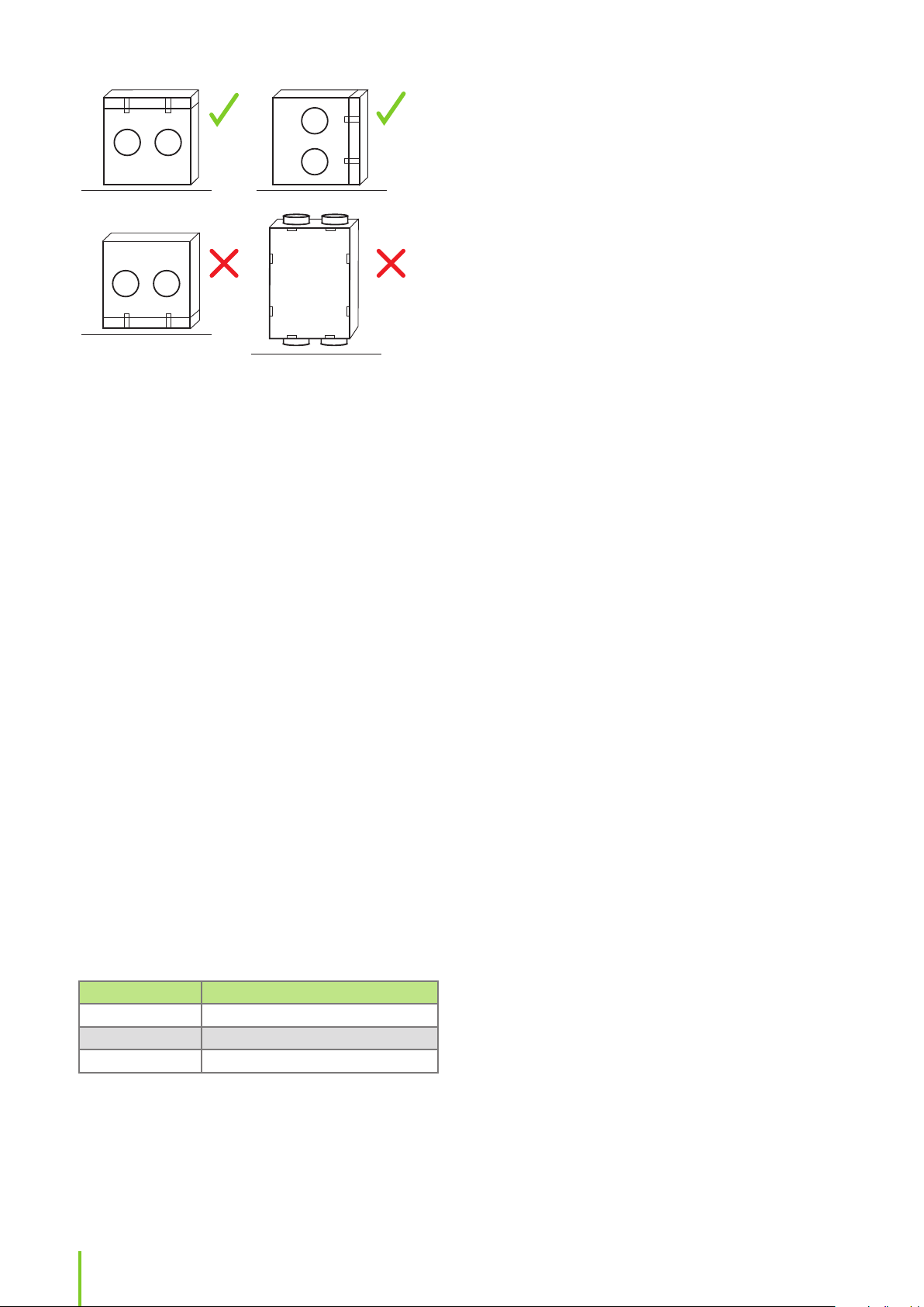
CAUTION: Do not install any LTR units so that
the maintenance hatch is facing downwards or
so that the unit is standing upright. Always make
sure that one of the condensate water drain is
downwards.
In two positions:
• Maintenance hatch up.
• Maintenance hatch on the side.
Maintenance hatch up.
• On request, units can be made
for installation with the hatch
on the side. This must be
mentioned when the unit is
ordered.
We recommend to order with the
maintenance hatch to the side.
• This will enable the
condensation formed in the
cooling coil to drain more easily.
Either warm or cold space.
• For example in a storage space
or attic.
CAUTION
9Installation instructions
Page 10
• Consult the ventilation planner regarding possible
need for additional insulation of the unit if
mounted in a cold space.
• If you use solid (hard) insulation, make sure
that the insulation does not carry sound to the
frame of the house.
• Do not install the unit in spaces with high
temperature and high humidity level.
• In certain conditions these can cause
condensation on the unit’s outer shell.
• Consider the unit noise level when choosing the
installation location.
• Do not install the ventilation unit directly
outside a bedroom, since even though the
ventilation unit is quiet, it is never completely
silent.
• Set the unit on top of a soundproong 100 mm
insulation.
• Make sure that it is possible to connect the
condensate water drain and water lock.
• Consider the space needed for the condensate
water connection.
• Make sure that you install re shuto valves if the
unit is placed in a separate re area.
• Consider the unit maintenance tasks when
installing the unit.
• Make sure that there is enough space in front
of or above the maintenance hatch:
Unit Free space in front of the hatch
LTR-2 and LTR-3 min. 50 cm
LTR-4 and LTR-6 min. 60 cm
LTR-7 and LTR-7 XL min. 70 cm
• Make sure that the electrical connections can be
easily accessed.
• Take into account the space needed for opening
the maintenance hatch locking latches.
• Consider the space needed for duct coils (if
included).
BUILDING THE VENTILATION
SYSTEM
Designing the ventilation system must be done by a
professional ventilation designer. By following closely
the design plan when building the ventilation system,
you ensure the operation of the whole ventilation
system and customer satisfaction. Use the Enervent
Energy Optimizer calculation program at the Enervent
home page to calculate the performance and estimated
heating/cooling power of a particular ventilation unit.
• Use type-approved factory made materials when
building the ventilation system.
• Use valves that are suitable for mechanical
ventilation.
• Do not cover the outside air grating with mosquito
net.
• This would make it very dicult to keep clean.
• Prevent rain water and snow from entering the
outside air and exhaust air duct.
• Install enough inspection hatches in the
ventilation network to enable cleaning of the
ventilation ducts.
• To make it easier to nd the inspection
hatches, mark their location for example on
the rafters.
• Ventilation systems for dierent re areas must be
separate.
• For example garage is one re area whereas
living quarters are another re area, which
means that they cannot be connected to the
same ventilation system.
• Use an extractor hood with its own fan, above the
stove.
• The extractor hood must have its own extract
duct directly out.
• A motorless extractor hood can be connected
to the ventilation unit only if the ventilation
unit has an extractor hood connection.
• The extractor hood used must be equipped
with a grease lter and a timer controlled ap
that prevents any airow through the extractor
hood when not in use.
• A drying cabinet with its own fan can be indirectly
connected to the outlet valve using the connection
system of the drying cabinet.
• A part of the extract air is taken from the living
space and a part from the drying cabinet.
• The extract air must ow through the valve at
a speed of 12 litres / second minimum.
• Install silencers at least in the supply and extract
ducts.
10
Page 11

• The amount of silencers must be considered
case by case.
• We recommend that automatically closing
dampers are installed in outside and exhaust air
ducts.
• In case of a power failure, the dampers will
close and block out cold air, preventing any
water coil from freezing.
• If cold air gets into ventilation ducts, it will
create condensate when mixing with warm air.
NOTE: The ventilation ducts must be blanked
o until the ventilation system is taken into use.
This is in order to keep warm air from owing
into the duct. Warm air causes condensation if
it meets cold outside air or surfaces in the duct.
Furthermore the plugging keeps dirt and other
unwanted particles from clogging the system.
Ventilation duct insulation
examples
EN
NOTE: Sound insulation is not taken into
account in these insulation instructions and
examples.
NOTE: Semi-warm space = +5°C - +15°C. A
semi-warm space refers also to dropped ceilings,
sub-oors, and casings.
Outside air duct (fresh air duct)
Cold spaces
Insulating ventilation ducts
Insulate the ventilation ducts appropriately. This is
especially important when the ventilation unit comes
with a cooling functionality.
Ventilation ducts must be thermally insulated to
prevent water from condensing to the inner or external
duct surfaces in any circumstances. Additionally, the air
temperature must not decrease or increase excessively
in the ducts because of external factors. The ventilation
engineer calculates the insulation requirements
depending on the placement of the ducts and the air
temperatures.
Ventilation duct thermal insulation in heating use
Supply air duct from
the ventilation unit to
the supply valve.
Extract air duct from
the extract valve to
the ventilation unit.
The insulation must be designed
and implemented so that the
maximum air temperature change
in the duct is less than 1°C.
The insulation must be designed
and implemented so that the
maximum air temperature change
in the duct is less than 1°C.
• 100 mm of sheet, mat, or pipe-covering insulation
(plus the blown wool, when used).
Warm/semi-warm spaces, dropped ceilings, suboors, and casings
• Option 1
• 80 mm insulation with vapour-proof external
surface.
• Option 2
• 20 mm of cellular rubber insulation on the
duct surface and 50 mm insulation with
vapour-proof external surface.
The insulation must prevent water vapour from
condensing to the external duct surface and excessive
air temperature rise during summer.
Supply air duct
Cold/semi-warm spaces and also by dropped
ceilings, sub-oors, and casings:
Ventilation duct thermal insulation in cooling use
Supply air duct from
the ventilation unit
to the supply valve.
Extract air duct from
the extract valve to
the ventilation unit.
The insulation must be designed
and implemented so that the
maximum air temperature change
in the duct is less than 1°C. At least
19mm of cellular rubber insulation
on the duct surface.
The insulation must be designed
and implemented so that the
maximum air temperature change
in the duct is less than 1°C.
• In standard ventilation the insulation must be
designed and implemented so that the maximum
air temperature change in the duct is less than 1°C.
• For example, 100 mm of sheet, mat, or pipecovering insulation can be used (plus the blown
wool, when used).
Warm spaces
• Insulation is not required in standard ventilation.
In heating and cooling use see tables "Ventilation duct
thermal insulation in heating use" on page 11 and
"Ventilation duct thermal insulation in cooling use" on
page 11.
11Installation instructions
Page 12

Extract air duct
Warm spaces
• Insulation is not required in standard ventilation.
Ventilation unit models equipped with duct coils for
after-heating or cooling (see table "Models with duct
coils" on page 36).
• These coils are installed in the supply air duct (after
the ventilation unit).
Cold/semi-warm spaces
• In standard ventilation the insulation must be
designed and implemented so that the maximum
air temperature change in the duct is less than 1°C.
• For example, 100 mm of sheet, mat, or pipe-
covering insulation can be used (plus the
blown wool, when used).
In heating and cooling use see tables "Ventilation duct
thermal insulation in heating use" on page 11 and
"Ventilation duct thermal insulation in cooling use" on
page 11.
Exhaust air duct
Cold spaces
• 100 mm of sheet, mat, or pipe-covering insulation.
Warm/semi-warm spaces
• Option 1
• 80 mm insulation with vapour proof external
surface.
• Option 2
• 20 mm of cellular rubber insulation on the
duct surface and 50 mm insulation with
vapour proof external surface.
The insulation must prevent water vapour from
condensing to the external and internal duct surfaces.
Extractor hood duct
• The extractor hood duct must be insulated and
constructed in accordance with local building and
re safety regulations.
Installing duct coils
Duct coils are used in several unit models both as preheaters, after-heaters and coolers. For information what
type of coils are used with your ventilation unit model,
refer to tables listing models with duct coils at the end
of this manual. For correct mounting of duct coils, refer
to the principal diagrams at the end of this manual.
Ventilation unit models equipped with pre-heating/precooling coils (see table "Pre-heating and pre-cooling
coils" on page 37).
• These coils are installed in the outside air duct
(before the ventilation unit).
• Duct coils must be accommodated in the
ventilation ducts.
• There must also be sucient room for
maintenance and draining of condensate water.
NOTE: For more technical details about the
coils, see the technical data table at the end of
this manual.
Duct coil for uids
When installing duct coils:
• Place the duct coil in the supply air duct after the
ventilation unit or in the outside air duct before
the ventilation unit depending on its function.
• Make sure that there is a lter before pre-heater
coils in the outside air duct to prevent dirt from
entering the coil.
• Do not install the coil too close to a fan outlet or a
bend in the ducting.
• This can result in lower eciency.
• Connect the coil so that the system is easy to
empty for maintenance.
• Install duct heaters in a horizontal or a vertical duct
with optional direction of airow.
• To facilitate venting of the coil, the unit
must be tted with the longitudinal tubes
horizontal.
• Install duct coolers in a horizontal duct with airow
in the direction of the arrow.
• Insulate the cooler externally to prevent the
formation of condensation.
• Connect the cooler to a condensate drain
and water trap and tilt it at an angle of 10-15
degrees to the horizontal in the direction of
the drain.
• Insert the coil into standard spiral ducting and
attach it to the ducting with screws.
• Support the weight of the coil.
• Connect the coil with clamping ring
connectors.
12
Page 13

• Connect the water inlet to the lowest pipe
connector in order to facilitate venting of the coil.
• Consult the principal drawings at the end of
this manual on how to construct the hydronic
circulating system.
• Install a venting valve near the coil or at the
highest point in the system.
• Inspect the duct coil and its connections for leaks
immediately after the system has been lled with
liquid.
• Place the supply air temperature sensor (TE10) in
the duct after the coil.
• Place the water coil return water sensor (TE45)
on the return water pipe of the coil, if the coil is
mounted in the supply air duct.
• Place the outside air temperature sensor (TE01)
in the outside air duct before the coil, if the coil is
mounted in the outside air duct.
• Connect the sensor to the ventilation unit control
circuit board.
• Refer to the electrical schematics at the end of this
manual for correct connections.
Electrical duct coils
NOTE: The heater is designed for insertion
into standard spiral ducting and is xed to the
ducting with screws.
• The distance from (to) the heater to (from) a duct
bend, valve, lter, etc., must be at least twice the
duct diameter.
• Otherwise there is a risk that the airow
through the heater will be uneven which can
cause activation of the overheating cut-out.
• Insulate the duct heater in accordance with local
regulations for ventilation ducting.
• Make sure that the insulation is incombustible.
• Do not cover the lid with insulation, since the
rating plate must be visible and the lid must
be removable.
• Do not cover any heatsinks, nor the side of the
connection box where the SCR’s (Triac’s) are
mounted with insulation.
• The duct heater must be accessible for
replacement and inspection.
• Make sure that the distance from the heater metal
casing to any wood or other combustible material
is at least 30 mm.
• Install the duct sensor TE10 (delivered with the
heater) in the duct after the heater, if the heater is
mounted in the supply air duct.
• If the heater is mounted in the outside air duct,
install the temperature sensor (TE01) before
the heater in the outside air duct and connect
the sensor(s) to the ESC control circuit board.
NOTE: We recommend installing a safety switch
for the electric heater.
EN
NOTE: The air must ow through the heater in
the direction indicated by the arrow on the side
of the connection box.
To install:
• Install the heater in either horizontal or vertical
ducting.
• The heater must only be tted in ducts that
are made of incombustible and heat-and-cold
resistant material.
• The connection box can be freely placed
facing upwards or sideways to a maximum
angle of 90°.
CAUTION
CAUTION: Do not install the connection box
facing downwards.
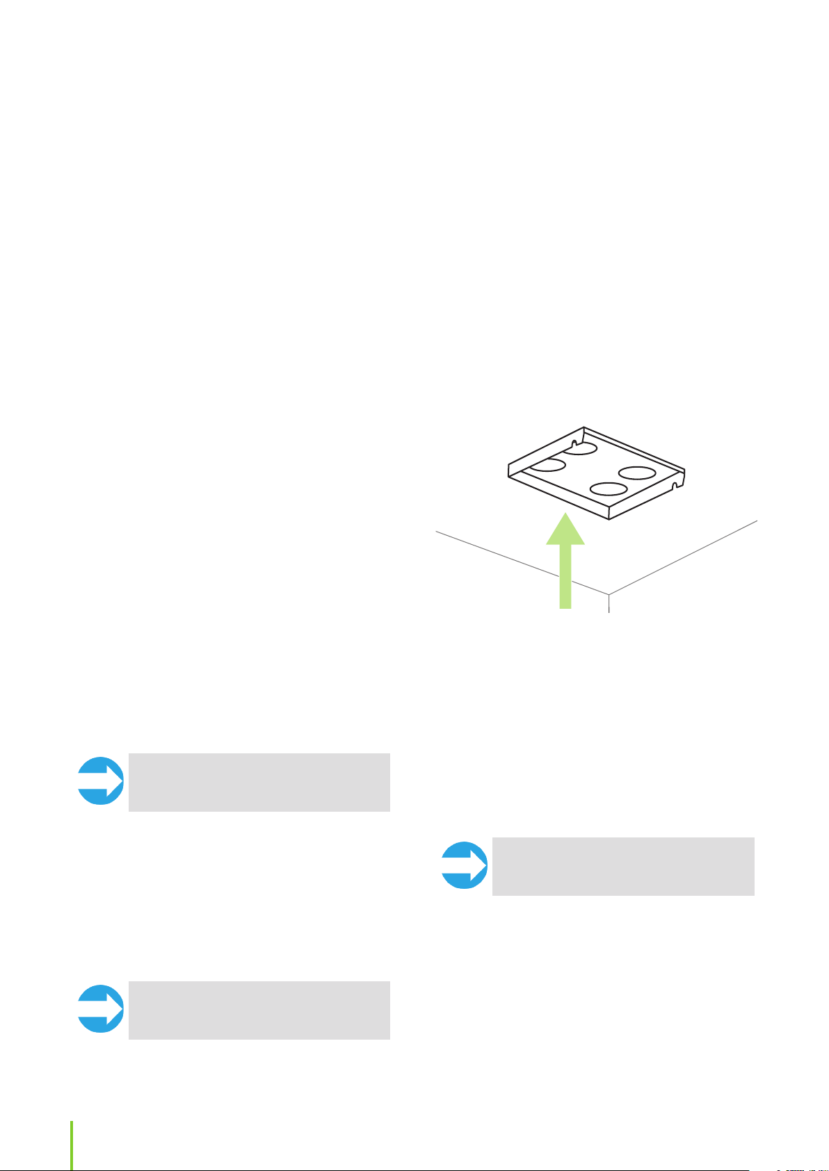
Installing ventilation unit ceiling
installation plate (OPTIONAL)
NOTE: Ceiling installation plate is separately
sold extra equipment available for ventilation
unit models Pinion, Pingvin, Pingvin XL and
Pandion.
Before installation:
• Make sure that the ceiling is even so that the plate
will be stable and straight when installed.
• The gap between the plate and the back wall must
be at least 10 mm (recommendation) and at least
15 mm between the plate and the side walls.
• The ceiling installation plate top surface must
not be more than 15 mm above the ceiling inner
height.
• Otherwise you will not be able to hook
the ventilation unit front on to the ceiling
installation plate.
13Installation instructions
Page 14

To install:
To install:
1. Prepare the holes in the ceiling for the ventilation
ducts.
2. Attach the plate on the ceiling using screws that
are suitable for the ceiling material.
3. Seal the ceiling installation plate against the
ceiling’s vapor barrier using for example duct tape.
4. Attach the ducts to the ceiling installation plate
with rivets.
• Make sure that there are no gaps between the
insulation and the ducts.
• Consider the unit’s weight when screwing the
plate to the ceiling.
• The ceiling installation plate must be
absolutely rigid.
• Weights for all units are found in the technical
table in the end of this manual.
Installing geo-cooling equipment
If a geothermal heat pump is in use, the cold brine in
the ground loop can be used in the summertime to
cool the incoming air.
The system can be implemented in two ways:
• In a standard delivery, a separate pump is used
(Option 1).
• Alternatively, the brine is circulated through the
geothermal pump (Option 2).
1. Install the cooling coil in the supply air duct (in
case of a duct coil).
2. Connect the condense water outlet.
3. Build a separate pump group with valve and
actuator for circulating cool brine adjacent to the
ventilation unit cooling coil.
4. Isolate the pipes carefully with vapour proof
insulation to prevent condensation on the outside
of the pipes in warm and semi-warm spaces.
• Follow the principal chart at the end of this
manual.
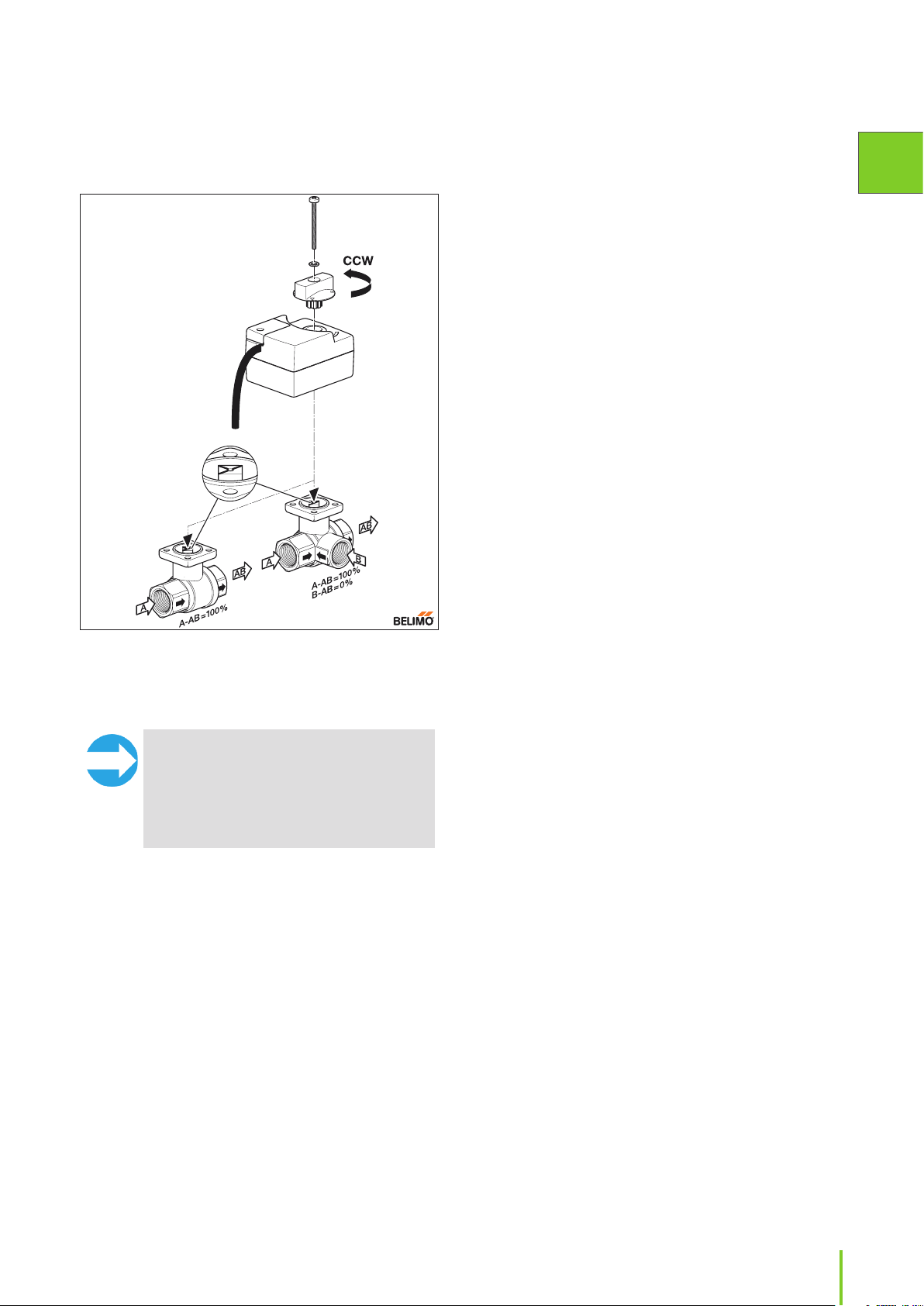
NOTE: The valve and actuator must be in the
same position when connected. When the valve
is in the open position, the actuator is turned
counter-clockwise before connecting, and
when the valve is closed, the actuator is turned
clockwise before connecting. Figure 1 on page
15 shows the valve and markings on valve
spindle in valve open (cooling/heating on max)
position.
5. Prepare / connect wiring between the ventilation
unit, the geothermal pump and the actuator, as
shown in the connection diagram at the end of
this manual.
Option 2
A geothermal heat pump is used for circulating brine
also in the supply air coil.
The cooling coil can be either built in the ventilation
unit or it can be a duct coil, depending on the model.
A duct coil is mounted in the supply air duct after the
ventilation device.
Detailed principal charts are found at the end of this
manual.
Option 1 (standard)
A separate pump is used for circulating brine in the
supply air coil.
The delivery includes:
• A relay for starting up the circulation pump for the
ventilation unit’s cooling coil.
• The relay is situated on the unit motherboard
connection DO8.
• A 3-way control valve (Belimo R3) needed for
cooling.
• An actuator (Belimo TR24-SR).
The temperature is controlled using the ventilation
unit’s own automatic control. The ventilation unit
controls the circulation pump and the 3-way valve.The
heat pump is not started up for ventilation cooling.
The delivery includes:
• A relay for starting up the brine pump.
• The relay is situated on the unit motherboard
connection DO8.
• A 3-way control valve (Termomix D32S) needed for
cooling.
• An actuator (Belimo NRYD24-SR-W + installation
set MS-NRE).
The temperature is controlled using the ventilation
unit’s own automatic control. The ventilation unit
controls the geothermal heat pump and the 3-way
valve.
To install:
1. Install the cooling coil horizontally in the supply air
duct (in case of a duct coil).
2. Isolate a separate loop for the cooling coil.
• Make sure to include the one-way valve.
• Follow the principal chart at the end of this
manual.
3. Connect the condense water outlet.
4. Install the 3-way valve and the actuator in the
ground collector’s piping.
14
Page 15
• The actuator controls the brine ow to the
cooling coil as needed.
5. Isolate the pipes carefully with vapour proof
insulation to prevent condensation on the outside
of the pipes in warm and semi-warm spaces.
• For example in Helsinki, the brine must still
be functional at -26°C whereas in Lapland the
temperature value is -38°C.
It is also possible to use earth to air heat exchangers
(earth tubes) for pre-heating or pre-cooling. The earth
tube must be combined with a normal outside air
duct and a damper that switches the outside air ow
between the earth tube and the normal outside air
duct depending on the actual need for pre-cooling and
pre-heating. The damper can be controlled from the
same relay that controls the circulation pump for the
hydronic pre-cooler / heater.
The CHG pre-heating / pre-cooling system can be built
as a separate system (option 1) or as a part of the geothermal heat system (option 2).
Detailed principal charts are found at the end of this
manual.
Option 1
A ground loop is built for the pre-heating / cooling
coil. To avoid freezing of the system, brine in the
loop must meet the local rated temperature value.
The ventilation unit automatic control regulates the
system’s temperature. The ventilation unit controls the
circulation pump and the 3-way valve.
EN
Figure 1. Valve and actuator open counter-clockwise and
close clockwise. The gure shows the valve and actuator
in the fully open position. Also, shown is the allowed direction of the liquid ow.
NOTE: The valve and actuator must be in the
same position when connected. When the valve
is in the open position, the actuator is turned
counter-clockwise before connecting, and
when the valve is closed, the actuator is turned
clockwise before connecting. Figure 1 above
shows the valve and markings on valve spindle
in valve open (cooling/heating on max) position.
6. Prepare / connect the wiring between the
ventilation unit, the geothermal pump and the
actuator.
Installing CHG geothermal preheating / pre-cooling equipment
A geothermal pre-heating / pre-cooling coil for
improving the system energy eciency can be installed
in the ventilation system. A duct coil is always used
when a hydronic pre-heating coil is needed. The coil is
installed in the outdoor air duct before the ventilation
unit. The duct or the coil must have a lter to keep dirt
out of the coil.
To avoid freezing the coil, the brine used in the coil
system must meet the local rated temperature value.
To install:
1. Install the cooling / heating coil in the outside air
duct.
2. Connect the condense water outlet.
3. Build a separate pump group for circulating cool
brine adjacent to the ventilation unit cooling /
heating coil.
4. Isolate the pipes carefully with vapour proof
insulation to prevent condensation on the outside
of the pipes in warm and semi-warm spaces.
5. Prepare / connect wiring between the ventilation
unit, the circulation pump and the actuator.
6. Install and connect the outside air temperature
sensor (TE01) in the outside air duct before the
duct coil.
• Refer to the electrical connection diagrams at
the end of this manual.
Option 2
A separate loop is isolated from the geothermal pump
brine loop for the cooling coil. To avoid freezing the coil,
brine in the loop must meet the local rated temperature
value. In addition to this, a heat exchanger is installed
in the coil system to ensure the functionality of the
geothermal pump. For the pre-heating / pre-cooling
coil to yield any benets there must be some ow in the
collector of the geothermal pump.
15Installation instructions
Page 16

Temperature is controlled using the ventilation unit’s
own automatic control. The ventilation unit controls the
circulation pump and the 3-way valve.
To install:
4. Isolate the pipes carefully with vapour proof
insulation to prevent condensation on the outside
of the pipes in warm and semi-warm spaces.
5. Install a heat exchanger in the coil system.
6. Install and connect the outside air temperature
1. Install the cooling coil in the outside air duct.
2. Connect the condense water outlet.
3. Build a separate pump group for circulating cool
brine adjacent to the ventilation unit cooling coil.
sensor (TE01) in the outside air duct before the
duct coil.
7. Prepare / connect wiring between the ventilation
unit, the geothermal pump and the actuator.
Refer to the electrical connection diagrams at the
end of this manual.
The functions and accessories listed in the following table may need external wiring or connecting to function:
eWind external connections
Connection/Functionality
AI NTC
TE01 Outside air temperature TE01 3.3VDC Quick connector 5m
TE10 Supply air temperature TE10 3.3VDC Quick connector 5m
TE45/TE46 Heating/cooling coil
return water temperature
Digital outputs DO Potential free contact
ON/OFF Control for heating DO2 Max 250VAC/50VDC
ON/OFF Control for dampers DO5 Max 250VAC/50VDC
A alarm output (NO) (Default)
ON/OFF Control for preheating (CHG/AGH or electrical
pre-heater)
ON/OFF Control for cooling (CG)
Analog inputs AI
%RH or CO2 external transmitter AI1 (user
Analog Outputs AO
Control voltage for heating AO5 0-10VDC 10mA KLM 2x0.8 Yes, if hydronic heating
Control voltage for pre-heater /
Control voltage for cooling
(CHG/CG)
Digital inputs DI Potential free NO
Emergency stop DI1 (xed) 24VDC KLM 2x0.8 Yes
Manual boost mode DI4 24VDC KLM 2x0.8 Yes
Away mode DI5 24VDC KLM 2x0.8 Yes
Overpressure mode DI6 24VDC KLM 2x0.8 Yes
Miscellaneous connections
Operating panel connectors OP1, OP2 10m cable supplied with
Modbus-RTU X26 Instrumentation cable
Location
on eWind
controller card
TE45 3.3VDC Quick connector 5m
DO8 Max 250VAC/50VDC
congurable)
AO6 0-10VDC 10mA KLM 2x0.8 Yes, except built in
Voltage/current Cable (example) Wiring outside AHU
cable supplied with AHU
cable supplied with AHU
cable supplied with AHU
MMJ 3x1.5 Yes, if hydronic heating
8A/2A inductive load
MMJ 3x1.5 Yes
8A/2A inductive load
MMJ 3x1.5 Yes, except built in pre-
8A/2A inductive load
0-10VDC KLM 4x0.8 Yes
contact
AHU
2x2x0.5
Yes, if pre-heater/
preecooler (CHG/
AGH) or electrical duct
mounted pre-heater
Yes, if duct heater/
cooler coil
Yes, if duct heater/
cooling coil (W/E-CG)
(W)
heater coil
(W)
pre-heater
Yes
Yes
16
Page 17

ELECTRICAL CONNECTIONS
DANGER
DANGER: Only an authorized electrician
is allowed to perform electrical work on the
ventilation units.
Refer to the electrical drawings at the end of this
manual.
Preparing for electrical
installations
Before you start the installation, make sure that:
• Appropriate power supply is available for the
ventilation unit.
• At least 30 mA fault current protection is installed.
• Because of this, no other electrical appliances
should be plugged into the same outlet.
• There is appropriate cabling between the unit and
the control panel wall mount.
• The cable must run inside a protective conduit
of at least Ø 20 mm.
• The cable included in the basic delivery is
10m. Optionally a 30 m cable is available.
• The cable heads are type RJ4P4C.
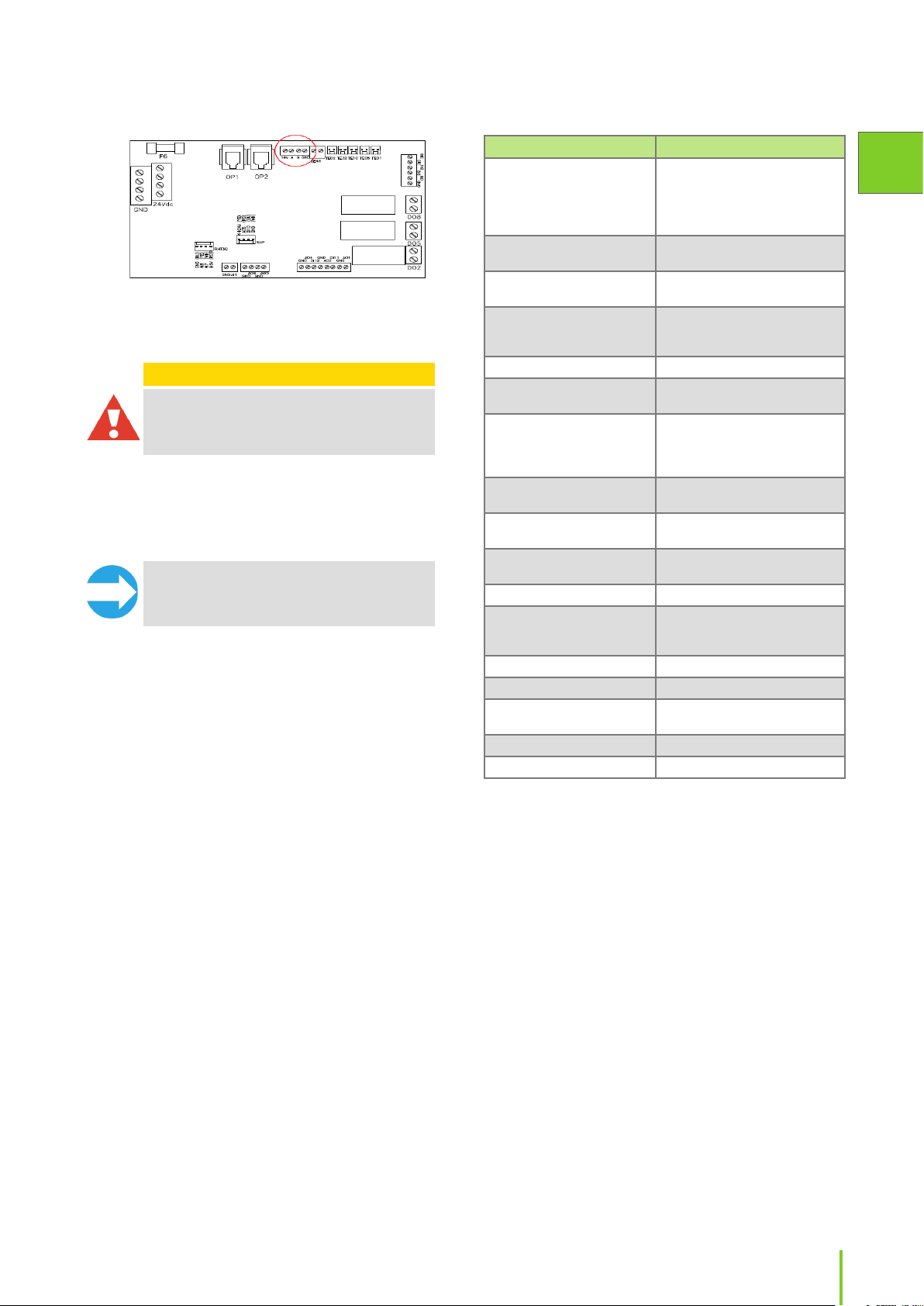
eWind card connections
eWind card connections
NTC sensors
Input Use
TE01 Outdoor temperature measuring TE01.
TE05 Supply air temperature after-heat recovery TE05.
TE10 Supply air temperature TE10
TE32 Exhaust air temperature TE32
TE02 Pre-heated outside air temperature TE02 (CHG/
AGH)
TE45 Return water temperature TE45 (W)
Return water temperature TE46 Option (CG).
Analog inputs AI 0-10V
Analog input AI1 for voltage range 0-10V
Functionality of this input is decided by user. (Parameter
c27)
Input Use
AI1 External CO2 or %RH transmitter
Analog inputs AI7 - AI8 for voltage range 0-5V
Functionality of these inputs are locked by software.
AI7 Extract air humidity RH30
AI8 Extract air temperature TE30
eWind card connections
Analog Outputs AO 0 - 10V
Output Use
AO1 Control voltage for supply fan
AO2 Control voltage for extract fan
AO4 Control voltage for HRW
AO5 Control voltage for heating
AO6 Control voltage for electrical pre-heater. Control
Digital outputs DO relays, potential free normally open
contacts.
Output Use
DO2 ON/OFF Control for heating
DO5 ON/OFF Control for dampers
DO8 A/AB alarm output NO (Default)
Digital inputs DI (buttons and indications).
Connection to GND only! No voltage allowed to be
connected to digital inputs.
Input Use
DI1 Emergency stop
DI2 External electrical after-heater or pre-heater alarm
DI4 Manual boost
DI5 Away mode. Away mode is active as long as the
DI6 Fireplace/extractor hood mode. The replace
DI11 Supply fan tacho input
DI12 Extract fan tacho input
Miscellaneous connections
OP1,
OP2
X26 ModBus RTU
24VDC +24VDC
GND GND
voltage for (CHG). Control voltage for cooler (CG)
ON/OFF control for pre-heating (optional)
ON/OFF control for cooling (CG/CHG/AGH)
(optional)
input is grounded.
switch is a momentary push-button switch.
Fireplace mode is active 10 minutes from when
input is grounded. If connected to a changeover
switch, the circuit must be cut for the mode to
reactivate. The extractor hood mode is active
as long as the input is grounded. The selection
between replace mode or extractor hood mode
is done in parameter c12.
Operating panel connections for eWind
EN
17Installation instructions
Page 18

External sensors
Installing eWind control panel
It is possible that external sensors must be installed
depending on model of ventilation unit.
• The sensor element for duct mounted
temperature, RH and CO2 sensors must be
installed inside the duct.
• Most temperature sensors are supplied with a
readymade 5m long cable.
• RH and CO2 sensors need wiring on site.
To install:
1. Choose the place for the sensor according to the
unit of measurement that is to be measured.
Refer to the control diagram at the end of this
manual.
2. Place the sensor in the duct at a straight segment,
at least 2x the duct Ø before and after any duct
coil, bends or ttings.
3. Drill a suitable hole for the sensor and a rubber
grommet in the duct.
4. Push sensors attached to a cable trough the
rubber grommet so that the sensor element is a
few centimetres inside the duct.
The rubber grommet must be air tight, and tight
enough that the sensor cable cannot slip through
by itself.
• You can use a cable tie to lock the sensor in
place.
5. Install sensors with rigid pipe type sensor elements
through an adjustable ange mounted to the duct.
• Push the sensor element through the ange
and lock in place with a screw at suitable
depth.
• Conduct electrical connections according to
the electrical schematics at the end of this
manual.
• The functions and accessories listed in the
table "eWind external connections" on page
16 may need external wiring or connecting
to function:
• Make sure the cable grommets in the duct and
ventilation unit are absolutely air and water
tight. If in doubt, use an elastic sealer to seal
the grommets.
6. To select a CO2 sensor active the CO2 boosting
function must be selected "on" from parameter
c27.
For more information on electrical connections, see
the control and connection diagrams at the end of this
manual.
The eWind control panel (see chapter "Control system,
eWind operating panel" on page 26) is installed
in a wall mounted recessed junction box, or using
the supplied surface mounted junction box. One
ventilation unit can be controlled with the maximum of
2 panels.
Installing one control panel
To install:
1. Install the connection cable supplied with the unit.
2. Attach the connection cable to the connector on
the eWind control panel.
3. Install the eWind control panel to the wall junction
box.
4. Attach the connection cable to connector OP1 of
the eWind controller card.
• Make sure the cable grommets in the ventilation
unit are absolutely air and water tight.
• If in doubt, use an elastic sealer to seal the
grommets.
Installing two control panels
If the ventilation unit is controlled with two control
panels, each panel is attached to the eWind controller
card with its own cable.
To install:
1. Install the eWind control panels as instructed
above. Attach the connection cable of the rst
eWind panel to connector OP1 and cable of the
second eWind control panel to connector OP2 of
the eWind controller card.
2. Remove jumper J1 from the eWind controller card.
Installing with Modbus
The ventilation unit can also be controlled via Modbus
connector X26.
Specication of Modbus:
• Modbus address 1 (default)
• Communication standard RS485
• Modbus trac via Modbus connector X26 of
controller card
• Speed 9600, 19200 or 115200 bps
• 8 bit
• No parity or parity.
18
Page 19
The order of Freeway connector’s pins is marked on the
controller card.
Additional installation materials
Modbus registers are available on Enervent webpage
www.enervent.
CAUTION
CAUTION: Do not connect the external bus to
the motherboard before the bus is programmed
and compatible with the unit control.
INSTALLATION
NOTE: Before you install the ventilation unit,
make sure that there are no foreign objects in
the ventilation unit and duct system.
• Refer to the model-specic dimensional drawings
in the back of this manual for your specic
ventilation unit type.
• Inspect the order of duct connections to avoid
cross connections.
• Do not start the ventilation unit when it is installed
until the building is taken into use.
• If the ventilation unit is started too early, the
ventilation system can be contaminated by
building dust.
• Make sure that the ventilation unit duct
connections are the same size as the duct.
• Use a circular duct tting to connect the unit
to the duct.
• Insulate the duct all the way to the unit casing.
Material Description of use
Screws For hanging the rear attachment
Sheet metal screws For attaching the rear attachment
Wall mounting box For installing eWind operating
Cables As specied in chapter "Preparing
Duct tape For sealing.
Insulation sheets (soft foamed
plastic)
Insulation material (foamed
plastic and/ or wool,
depending on where the unit
will be installed)
Rivets For attaching the ventilation
Spirit level For making sure that the unit is
Water pipe For connecting duct coils and for
Water trap For condensate water drain.
Reducing ttings for duct
connections
Dampers To keep cold air out.
Silencers To reduce possible noise.
Suitable grommets for duct
mounted sensors
Shut-o valves To facilitate servicing of unit.
Hydronic balancing valves To properly adjust the water ow.
bracket and ventilation unit on
the wall (if applicable). Select
the screws according to the wall
material.
bracket onto the ventilation unit.
panel.
for electrical installations" on
page 17.
For preventing structure-borne
noise.
For retaining heat and coolness.
ducts onto the unit.
level.
disposing of condensate water.
For tting the ducts in the
ventilation system. NOTE: Always
use reducing ttings, if necessary.
For mounting sensors in the
ducts.
EN
19Installation instructions
Page 20
Installing models Pinion, Pingvin,
Pingvin XL, Pandion, Pelican,
Pegasos and Pegasos XL
Wall installation
• Make sure that the ventilation ducts are
insulated according to the instructions in
chapter "Insulating ventilation ducts" on page
11.
5. Make the applicable electrical and plumbing
connections according to the electrical and
principal diagram at the end of this manual.
Pinion, Pingvin, Pingvin XL and Pandion
To prepare:
1. Prepare the holes in the wall.
2. Bring in the ducts through the cross cut in the
vapor barrier to the height to which the unit will
be mounted.
3. Seal the gap between the duct and the vapor
barrier using for example duct tape.
4. Install an insulating plate at the back of the
ventilation unit or otherwise prevent the structure
borne noise.
• Soft foamed plastic sheets are recommended
(not included in the delivery).
5. Install an extra layer of insulation outside the
ventilation unit (for example foamed plastic), if the
unit is installed with its side against exterior wall
or if there is any other reason to suspect that the
outside of the unit will condensate.
• Condensation risk is present in areas where the
climate is cold.
• Installation varies for dierent models.
To install:
1. Install the rear attachment bracket at the desired
height.
2. Lift the unit on the bracket.
NOTE: Remove the heat exchanger before you
lift the unit. This will make the unit much lighter
to handle. Remove or secure the doors so that
they do not open during lifting.
Ceiling installation
Pinion, Pingvin, Pingvin XL and Pandion
The dimensional drawings for each of the models can
be found at the end of this manual.
To install:
1. Install the installation plate on the ceiling.
2. Install the supplied duct couplings and insulation
rings (Pingvin, Pingvin XL and Pandion), or
insulation sheet (Pinion) on top of the unit.
3. Unscrew the cover of the electrical cabinet.
• Prepare the lead-ins on unit for the cables
coming through the ceiling.
• Leave the electrical cabinet cover open.
4. Guide the unit power cable to run in front of the
hook to keep the cables from squashing between
the unit and the ceiling installation plate.
3. Attach the unit to the wall by the upper mounting
lugs.
• Make sure to install the rubber bushings for
the fastening screws. (Pingvin and Pandion
only).
4. Attach the rear attachment bracket to the unit’s
base using sheet metal screws.
NOTE: It is essential for the proper disposal of
condensate water that a Pingvin unit is installed
slightly tilted backwards. This must be veried
using a spirit level.
20
NOTE: Remove the heat exchanger before you
lift the unit. This will make the unit much lighter
to handle. Remove or secure the doors so that
they do not open during lifting.
• Make sure that there is enough space
underneath the ceiling plate to t the unit.
5. Lift the unit up.
6. Hook the unit to the front side of the ceiling
installation plate.
Page 21

7. Connect the cable(s) coming through the ceiling
plate to the electrical enclosure box.
• Make sure that the unit is hanging straight,
directly in the middle of the ceiling plate.
8. Push the base of the unit upwards until it locks
onto the ceiling plate.
CLICK
NOTE: Make sure to leave the cables loose in
case the unit must be taken down for some
reason.
EN
NOTE: It is essential for the proper disposal
of condensate water that a Pingvin unit is
installed slightly tilted backwards. The unit
is automatically installed tilted in the ceiling
installation plate.
Taking down ceiling installed units
DANGER
DANGER: Before taking the unit down, make
sure that the unit’s supply voltage has been
switched o.
CAUTION
CAUTION: Make sure you are holding the unit
in its place when opening the locking plates.
When the locking plates are opened, the unit’s
back side disengages from the ceiling plate.
Make sure that you have enough space under
the unit for it to swing down.
9. Secure the unit in place by tightening the two
security screws on both sides of the ceiling plate.
• The locking screws for Pinion units are below
the ventilation unit.
10. Put the heat exchanger back in the unit and close
the electrical cabinet door.
11. Reinstall the doors if you removed them before the
lifting.
12. Make the applicable electrical and plumbing
connections according to the electrical and
principal diagram at the end of this manual.
To take down:
1. Open the security screws.
2. Open the electrical cabinet and disconnect the
cables coming from the ceiling.
3. Holding the unit securely in its place, twist both
of the locking plates open (towards you) using a
screwdriver.
4. Lift down the unit.
21Installation instructions
Page 22

Floor installation
Pandion, Pelican, Pegasos and Pegasos XL
• Make sure that there is enough space left in
front of or above the maintenance hatch:
• Tilt the unit slightly in the direction of the
condensation drain.
Dimensional drawings for each of the models can be
found at the end of this manual.
To install:
1. Set the ventilation unit on the oor or on the
platform standing on its own rubber feet.
• Make sure there is at least a 10 mm gap all
around the unit.
• If the unit is installed with its side against a
wall, a 15 mm gap is required so the hatch can
be fully opened.
2. Note the space needed for disposing of
condensate water and the water trap under the
unit (if applicable).
• Make sure there is at least 95 cm of space in
front of the unit’s maintenance hatch and
that the electrical connections can be easily
accessed.
3. Connect the unit to a condensate water disposal
drain with water trap.
4. Connect the ducts to the ventilation unit using
rivets.
5. Insulate the ducts according to the instructions in
Insulating ventilation ducts section.
6. Make the applicable electrical and plumbing
connections according to the electrical and
principal diagram at the end of this manual.
Installing models LTR-2, LTR-3,
LTR-4, LTR-6, LTR-7 and LTR-7 XL
Dimensional drawings for each of the models can be
found at the end of this manual.
Consult the ventilation planner regarding possible
need for additional insulation of the unit if mounted in
a cold space.
Unit Free space
LTR-2 and LTR-3 min. 50 cm
LTR-4 and LTR-6 min. 60 cm
LTR-7 and LTR-7 XL min. 70 cm
3. Note the space needed for opening the
maintenance hatch locks.
• Make sure the electrical connections can be
easily accessed.
4. Connect the ducts to the ventilation unit with
circular duct ttings using rivets.
5. Insulate the ducts according to the instructions
in chapter "Insulating ventilation ducts" on page
11.
6. Connect the unit to a condensate water disposal
drain with water trap.
• If the ventilation unit is equipped with a
built-in cooling coil it is recommended to
install the unit with the service hatch to the
side to enable the condensate water to drain
more easily.
• LTR-4 units with cooling coil have two optional
32mm condensation drains. One drain is
welded shut and the other is ready to use.
Depending on the way the LTR-4 unit is
installed, the drain that becomes lower is to
be used. If the lower drain is the welded one,
a short piece of the pipe is sawed o to open
the pipe, and the water trap is connected to
the pipe.
• The unused condensation drain must be
plugged.
7. Make the applicable electrical and plumbing
connections according to the electrical and
principal diagram at the end of this manual.
Installing model eWind W
If you are using solid (hard) insulation, avoid fastening
the isolation in a way that conducts sound and
vibration to the house frame.
To install:
1. Set the unit on top of an insulating plate.
• For example a chipboard covered with
100mm of hard insulating wool – above the
rafters in the attic or on a separate shelf in a
storage etc.
2. Note the space needed for disposal of condensate
water and the water trap.
22
Principal, control and wiring diagrams for each model
can be found at the end of this manual.
Check the principal charts for units with uid coil. Install
and connect the water pipes according to these charts.
To install:
1. Install the dampers and damper motors.
2. Install and connect the water pipes.
3. Install the valve and the valve actuator.
Page 23
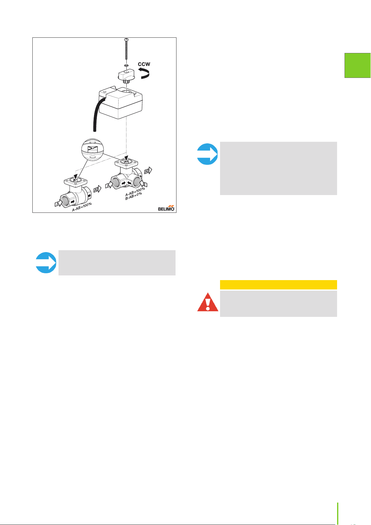
• Do not connect Modbus until all installation
and commissioning work is done.
7. Install over voltage protection to the unit.
8. Open the unit’s maintenance hatch and make sure
that:
• The unit is clean from the inside
• There are no unwanted objects inside
• The lters are in place and
• The condensate drain works.
9. Close the hatch carefully.
10. Connect the unit to an appropriate electric supply.
NOTE: The valve and actuator must be in the
same position when connected. When the
valve is in open position, the actuator is turned
counter-clockwise before connecting, and
when the valve is closed, the actuator is turned
clockwise before connecting. Figure 2 on page
23 shows the valve and markings on valve
spindle in valve open (cooling/heating on max)
position.
EN
Figure 2. Valve and actuator open counter-clockwise and
close clockwise. The gure shows the valve and actuator
in the fully open position. Also, shown is the allowed direction of the liquid ow.
NOTE: Do not install the actuator so that the
manual control faces downwards.
4. Connect the water.
• Do not connect to a point where the water
circulation ends for example during hot water
production.
5. Check the duct coil and its connections for leaks
immediately after the system has been lled with
water.
• The water heating coil needs a steady ow
of suciently warm water without large
temperature uctuations.
• Adjust the water ow in the heating coil
according to the technical features table at the
end of this manual.
• If the water is taken for instance from a ground
source heat pump, the heating coil needs its
own circulation pump.
• If the installation is done in wintertime it is
recommended not to let water in the coil until
the ventilation is running. This is in order to
prevent cold air from entering the ventilation
system and possibly freezing the coil.
6. Connect the external cables such as the cable
between the unit and the control panel, supply
sensor, actuator and pump.
Draining condensate water
All Enervent ventilation units must be drained. When
air cools down (condenses), condense water forms.
For example in winter time when humid inside air
meets cold heat recovery wheel, or when warm outside
air meets the cooling coil in the ventilation unit (if
applicable).
CAUTION
CAUTION: The condense water drain must not
be directly connected to a sewer pipe.
• The condensate water should be led in a falling, at
least Ø15 mm pipe, through a water trap to a oor
drain or such.
• The pipe must at all times lie lower than the
condensate water drip pan / condensate water
connection of the ventilation unit.
• There must not be any longer horizontal sections
on the pipe.
• The condensation drain pipe must be insulated if
mounted in spaces where freezing can occur.
• Only one water lock is allowed for each condensate
water drain.
• If the unit is equipped with more than one
condense water drains, each one must have a
water lock of its own.
• There is underpressure in the ventilation unit. We
recommend a height dierence of (A) 75 mm,
or at least the underpressure divided with 10 in
millimeters (i.e. 500 Pa under pressure -> 50 mm),
between the unit drain and the water lock drain.
23Installation instructions
Page 24
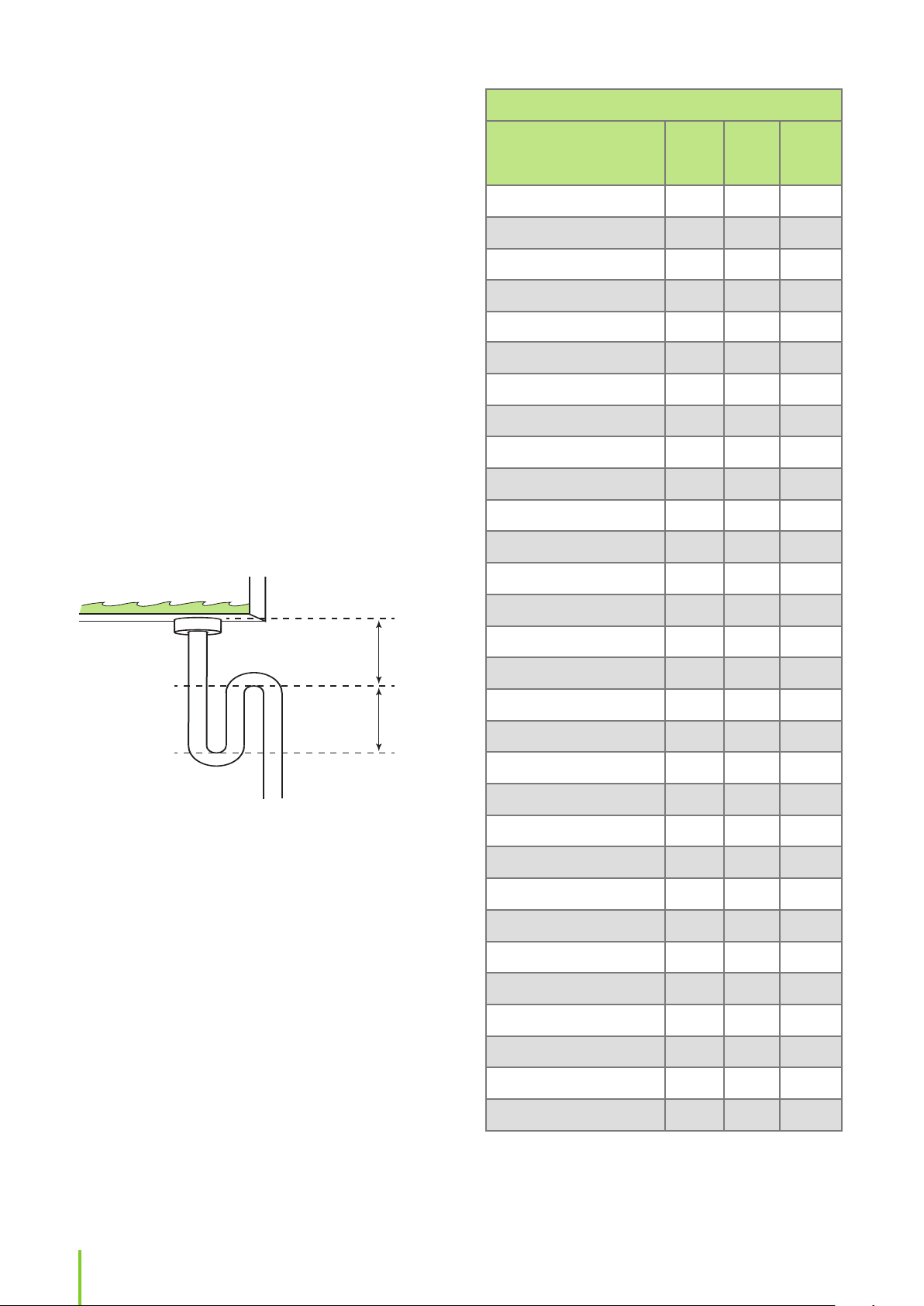
• We recommend that the height of backwater
A
B
in the water lock (B) is 50 mm, or at least the
underpressure divided with 20 in millimeters
(i.e. 500 Pa under pressure -> 25 mm height of
backwater). The above also applies to duct coils for
cooling mounted in the outside air duct or extract
air duct.
• There are over pressure inside duct coils mounted
in the supply air duct. We recommend the height
dierence (A) between the duct coil drain and the
water lock drain is 25 mm. The water lock height of
backwater (B) must be 75 mm, or at least the over
pressure divided with 10 in millimeters (i.e. 500 Pa
under pressure -> 50 mm).
• The water lock must be lled with water before
starting up the unit. The water lock might dry up
if water is not accumulated in it. If this happens,
air might get into the pipe and hinder water from
entering the water lock, which might result in an
irritating ”bubbling” sound.
• The functionality of the water lock must be
checked every year before the heating season and
also in the spring if the ventilation unit is equipped
with cooling.
CONDENSATE WATER DRAIN TABLE
Unit
Pinion eWind (E)/(W) •
Pingvin eWind (E)/(W) •
Pingvin eWind E-CG/CHG • •
Pingvin XL eWind (E)/(W) •
Pingvin XL eWind E-CG/CHG • •
Pandion eWind (E)/(W) ••
Pandion eWind E-CG • • •’
Pandion eWind E-CHG •• •
Pelican eWind (E)/(W) ••
Pelican eWind E-CG • • •’
Pelican eWind E-CHG •• •
Pegasos eWind (E)/(W) ••
Pegasos eWind E-CG • •
1/4”
(inner
thread)
DN32
G½”
(VEAB,
outer
thread)
Pegasos eWind E-CHG •• •
Pegasos XL eWind (E)/(W) ••
Pegasos XL eWind E-CG/CHG •• •
LTR-2 eWind (E)/(W) ••
LTR-2 eWind E-CHG •• •
LTR-3 eWind (E)/(W) ••
LTR-3 eWind E-CG/CHG •• •
LTR-4 eWind (E)/(W) ••
LTR-4 eWind E-CG •• •• •’
LTR-4 eWind E-CHG •• •
LTR-6 eWind (E)/(W) ••
LTR-6 eWind E-CG •• • •’
LTR-6 eWind E-CHG •• •
LTR-7 eWind (E)/(W) ••
LTR-7 eWind E-CG/CHG •• •
24
LTR-7 XL eWind (E)/(W) ••
LTR-7 XL eWind E-CG/CHG •• •
• condensate drain
•• two condensate drains of the same size
•’ option
Page 25

COMMISSIONING
Commissioning checklist
Requirements
For the ventilation unit to start running, it needs:
• Minimum +8 °C return water temperature (if
applicable)
• Supply and extract air below +55 °C.
For the ventilation unit to stay running, it needs:
• Minimum +10 °C measured extract air temperature
• Above +5 °C heat recovery supply air
• Above +10 °C supply air temperature
• All foreign objects removed from the ventilation
system.
• Both fans operating.
Calibrating airow
After the unit has been switched on, the airows must
be calibrated to the planned values.
• The airow calibration is performed at start-up of
the ventilation unit.
• The airow calibration is done separately for both
fans for each mode selection (=fan speed) of the
ventilation unit.
When calibrating, make sure that:
• All lters are clean
• All supply and extract air valves, the roof passthrough and the outside air grating are in place.
NOTE: Do not cover the grating with a
mosquito net.
To achieve optimal values during calibration the
airows must be measured at each duct opening. A
suitable measuring instrument is a thermo anemometer
or dierential pressure meter. With the help of
registered values, airow can be regulated to achieve
the projected values.
A correctly calibrated ventilation unit is quiet and gives
a good heat return and also upholds a small underpressure in the house. The underpressure prevents
humidity from entering the walls and ceiling.
Item Checked Notes
The unit has been
installed in its
place according
to the installation
instructions provided
by the manufacturer.
Condensate water
disposal pipe has
been connected to
the drain’s water lock
and tested.
Silencers have been
installed in the
supply and extract
air ducts.
For models with
water coils: dampers
have been installed.
All liquid coils are
connected, the liquid
ow(s) adjusted, and
the connections are
checked for leaks
All external valves
and valve actuators
are connected and
checked for correct
operation.
For CHG model:
coil, control valve,
valve actuator and
temperature sensor
for outside air duct
have been installed
and connected,
checked for correct
operation, and the
brine ow adjusted.
The freezing point
of the brine liquid
checked to be
sucient.
Terminal devices
have been
connected to the
ventilation network.
Outside air grating
has been installed for
fresh air intake.
NOTE: Do not cover
the grating with a
mosquito net. It will
make it very dicult
to clean.
Unit is connected
to an appropriate
electric supply.
Control panel has
been connected.
All external
sensors have been
connected and
checked for correct
operation.
The ventilation
ducts are insulated
according to the
ventilation plan.
EN
25Installation instructions
Page 26
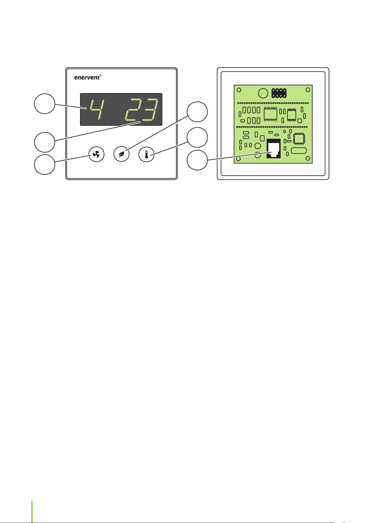
Control system, eWind operating panel
1
4
2
3
1. Mode (in basic display) 2. Temperature (in basic display) 3. Mode button
4. Eco button 5. Temperature button 6. Cable connector
Important to know about control
5
6
Setting up fan speeds
system
The fan speed settings for each operating mode must
Factory settings are suitable for most installations.
The fan speed settings for dierent operating modes
are installation specic and must be specied and
set separately for each installation. Otherwise, do not
change the factory setting, unless otherwise specied
in the ventilation system plan.
Make sure that you have all the necessary information
at hand before starting the setup.
be specied and set separately for the installation. Refer
to the parameter table for settings
To set up:
1. Press the Eco and Temperature buttons
simultaneously three times.
2. Use the Mode and Eco buttons to select
parameters c1-c 32.
• Refer to "Parameter list" on page 27 for
meaning of each parameter.
3. Press the Temperature button for 3 seconds select
the parameter to adjust.
4. Use the Mode and Eco buttons to change the
parameter value.
5. Press the Temperature button to conrm the
value and return to selection of parameters
c1 - c32.
6. Press the Eco and Temperature buttons
simultaneously once to exit the setup.
26
Page 27

Parameter list
Parameter Description
c1 Extract fan speed, mode 1,
range: 20-100%, step: 1%
c2 Supply air fan speed, mode 1,
range: 20-100%, step: 1%
c3 Extract fan speed, mode 2,
range: 20-100%, step: 1%
c4 Supply air fan speed, mode 2,
range: 20-100%, step: 1%
c5 Extract fan speed, mode 3
range: 20-100%, step: 1%
c6 Supply air fan speed, mode 3
range: 20-100%, step: 1%
c7 Extract fan speed, mode 4
range: 20-100%, step: 1%
c8 Supply air fan speed, mode 4
range: 20-100%, step: 1%
c9 Manual boost time limit (mode 4)
range: 1...4 h, step: 1 h
c10 Extract fan speed, replace/extractor hood
mode range: 20-100%, step: 1%
Factory
setting
36% Away mode 102
35% Away mode 100
56% Home mode 52
55% Home mode 51
83% Maximum eect also
80% Maximum eect also
100% Manual boost mode 68
100% Manual boost mode 67
2 h 66
30% Overpressure mode 55
Remark
by RH ja CO2 boost
mode
by RH ja CO2 boost
mode
Modbus
registration
74
72
Field
setting
EN
c11 Supply air fan speed, replace/extractor hood
mode range: 20-100%, step: 1%
c12 Overpressure mode time limit
range: 5...15 min
step: 1 min
c13 Heat recovery defrosting
on or oFF
c14 Service reminder interval
4 or 6 months
c15 CHG/AGH pre-heating and AGH pre-cooling,
on or oFF
c16 CHG/AGH outside temperature TE01, below
which pre-heating is used
range: 0…10°C, step 1°C, (for pre-heating)
c17 CHG/AGH pre-heating not in use when outside
air temperature (TE01) rises above value (c16)
+ (c17)
range: 1…5°C, step 1°C
c18 CG cooling or CHG pre-cooling on/oFF on Valid for CG and CHG
c19 Outside temperature TE01, above which
cooling is allowed
c20 AGH outside temperature above which earth
channel is used
range: 15…25°C, step 1°C, (for pre-cooling)
c21 AGH pre-cooling not in use when outside air
temperature (TE01) drops below value (c20c21)
range: 1…5°C, step 1°C
c22 Temperature setup for air temperature after
electric pre-heater
range: -10…-20°C, step: 1°C
c23 Humidity boosting
on or oFF
50% Overpressure mode 54
10 min Extractor hood mode
selected when set to 0
oFF Coil 55
4 Register value in days 538
on Coil 58
5°C 592
1°C 593
heat exchangers
17°C 164
20°C 629
2°C 630
-15°C 591
on Coil 19
56
Coil 52
27Installation instructions
Page 28

Parameter list
Parameter Description
c24 Summer/winter temperature threshold,
range -10…+10 °C, step 1 °C
c25 RH boosting threshold,
range 10…100 %RH, step 5%
c26 Humidity boosting start threshold range:
5…30% RH exceeding 48h average, step 5%
c27 CO2 boosting
on or oFF
c28 CO2 boosting start threshold range:
600...1200 ppm, step: 100 ppm
c29 Boosted dehumidication with HRW rotor
on or oFF
Factory
setting
4 °C Outside air 24 h
45% In winter mode RH
15% In summer mode RH
oFF If on congures AI1 for
1000 ppm 76
oFF Coil 24
Remark
temperature average.
When over threshold,
RH boosting is in
summer mode, when
under threshold, in
winter mode.
boosting starts when
RH value exceeds the
threshold.
boosting starts, when
RH exceeds the 48 h
RH average by the
threshold value.
external CO2 sensor
Modbus
registration
137
69
70
Coil 21
Field
setting
c30 Display dimmed in stand-by
on or oFF
c31 eWind motherboard Modbus address
range: 1...99, step: 1
c32 Modbus bus speed
1=9600, 2=19200, 3=115200
Information view
You can view the active functions from eWind Info list
shown in the information display.
eWind Info list
To open:
1. Press Eco and Temperature buttons
simultaneously once.
• A parameter (n1..nn) is shown in the display.
2. Browse the Info list with Mode and Eco buttons.
To return to the basic view:
1. Press the Eco and Temperature buttons
simultaneously once.
NOTE: Without input the menu closes after 5
minutes and the panel switches back to basic
display.
oFF Panel specic setting
oFF: display o in
stand-by,
on: dimmed display in
stand-by.
1 640
2 19200bps 733
eWind Info list
Designation Explanation
n0 Basic mode in use
n1 Ventilation boosted by %RH
n2 Ventilation boosted by CO2
n3 Heat recovery in use
n4 After-heating by electrical or water coil in
use
n5 Outside air pre-heating by CHG/AGH or
electrical pre-heater in use
n6 Supply air cooling by CG, CHG or AGH in use
n7 Cool recovery by rotating heat exchanger
in use
n8 Ventilation manually boosted
n9 Away mode in use
n10 Rotor dehumidication in use
n11 Defrosting in use
n12 ECO mode in use
n13 Service reminder; Days remaining to next
lter change
n14 Unit starting up
Internal
28
Page 29

Measurements view
eWind Measurements list
You can follow the temperature, humidity, heat
recovery eciency among other measurements in the
eWind Measurements list shown in the measurements
display.
To open:
1. Press the Eco and Temperature buttons
simultaneously twice.
• A parameter (r1..rn) and the value of the
parameter are shown in the display.
•
2. Press the Mode or Eco buttons to scroll the
parameter list up or down.
To return to the basic view:
1. Press the Eco and Temperature buttons
simultaneously once.
eWind Measurements list
Designation in
Designation Explanation
r1 Outside air temperature, °C TE01 All models 6
r2 Supply air temperature after-heat
recovery, °C
r3 Supply air temperature, °C TE10 All models 8
r4 Extract air temperature, °C TE30 All models 10
r5 Exhaust air temperature, °C TE32 All models 9
r6 Return water temperature of water
heating coil, °C
r7 Pre-heated outside air temperature
(CHG/AGH/electrical pre-heater), °C
r8 Relative humidity of extract air, %RH RH30 All models 13
r9 CO2 level, ppm Without external CO2 sensor
r10 External relative humidity
measurement, %RH
r11 Supply air heat recovery temperature
eciency, %
r12 Extract air heat recovery temperature
eciency, %
schematics and
connection on
eWind main board
TE05 All models 7
TE45 W only. Other models show “0” 12
TE02 Only if equipped with CHG/
Note
AGH or electrical pre-heater)
(accessory) showing "--”
Without external %RH sensor
(accessory) showing "--”
All models
Calculated value
All models
Calculated value
EN
Modbusregister
32
23
23
29
30
Documenting commissioning
• Fill in the warranty.
• Mark down the possible changes you made to the
factory settings to the column Field settings in the
table "Parameter list" on page 27.
• Fill out the air amount measuring document. A
copy of the measuring document is provided at
the end of this manual.
NOTE: The warranty does not apply for units
with no documented air amount measuring.
NOTE: It is very important to write down all the
changes made to the parameters. This way the
information is backed up in case the automation
gets damaged (for example by a lightning).
29Installation instructions
Page 30

USING THE EQUIPMENT
Introduce the end user to proper use of the ventilation
unit and the control panel.
NOTE: If you run into problems while using
the ventilation unit, please consult the
Troubleshooting guide at the end of this
manual.
General
• If the unit is not to be used for a longer period
of time, it can be shut down if you cover both
the outside air intake and the exhaust air
outtake.
• In this way you stop moisture from condensing
on for example the fans’ electric motors.
• Before the heating season in the Autumn
and before there is cooling need (if unit is
equipped with cooling) the functionality of
the condensation drain(s) must be checked by
pouring water into the drain and checking that
the water is drained away.
CAUTION
CAUTION: Do not switch the ventilation unit
o. It must always be kept running at the power
specied by the ventilation designer.
• Ventilation must be sucient.
• If the ventilation is insucient, the humidity
indoors becomes too high and can result in the
formation of condensation on cold surfaces.
• Indoor humidity levels must be checked regularly.
• In winter an indoor relative humidity of
max. 40 - 45% is recommended (room
temperature of +20 - 22°C). At these levels
the humidity will be at a healthy level and the
risk of condensation is drastically diminished.
Humidity levels can be checked with a
hygrometer. When the humidity rises above
45%, ventilation needs to be increased, and
when the humidity goes lower than 40%,
ventilation can usually be lowered.
• Cleanliness of the lters must be checked regularly.
• During winter the extract air lter usually
become dirty sooner than the supply
air filter. As a result of this, the extract air ow
decreases, which leads to a higher indoor
humidity. This also leads to poor heat recovery.
NOTE: If you run into problems while using
the ventilation unit, please see the chapter
"MAINTENANCE" on page 32.
Fans
When electricity is connected to the ventilation unit
the relay controlling the dampers activates and heat
recovery turn on full power. After a while the extract
fan starts up and after a small delay, also the supply
fan. After that the ventilation unit runs according to the
dened settings.
The fans are operating at specic speed, based on the
prevailing mode. During commissioning of ventilation
unit, a specic fan speed is assigned to each mode.
Supply and extract fans have each their own fan speeds.
Modes that aect the operating speed of the fans are:
• Mode 1, 2, 3 or 4
• CO (accessory) or %RH boosting
• Away
• Manual boosting
• Overpressure
• Alarm modes A and AB
Supply and extract fan speed is assigned to each of
these modes, not including alarm modes.
CO (accessory) and humidity
boosting of fans
The ventilation unit fan speed is controlled by data
received from humidity and/or CO2 (accessory) sensors.
• Make sure monthly that the heat exchanger is
rotating correctly.
NOTE: For more information on checking and
cleaning the heat exchanger, please see chapter
"MAINTENANCE" on page 32.
30
When CO2 boosting is selected, the external analog
input (AI1) is automatically congured as a CO2 sensor
input.
CO and/or humidity content of a space is meant to be
kept below the limit set in the control panel. Humidity
control commands the fans based on data from
internal and possible external humidity transmitters
of the ventilation unit. One built-in humidity sensor is
included in the standard unit delivery.
Page 31

CO boosting and humidity boosting may activate
in mode 2 or 3. Additionally, humidity boosting may
activate also in mode 1.
If humidity boosting is not sucient to remove excess
humidity from the premises, the rotor dehumidication
function can be activated. When humidity boosting is
active, rotor dehumidication activates automatically
if the outside air temperature is below 0 °C and the
functionality has been activated. This functionality
slows the heat exchanger rotation down, so creating
conditions for extracting greater volumes of humidity.
Fireplace/extractor hood mode
Fireplace mode control can be activated directly from
the control panel or by using a separate button (extra
equipment), which makes lighting of a replace easier.
Length of overpressure and supply and extract fan
speed can be set in the control panel. Fireplace mode
can be aborted from the control panel. Fireplace mode
lowers the extract fan speed and accelerates the supply
fan speed for 10 minutes (default setting).
NOTE: Fireplace mode is only to be used as a
temporary help for lighting of the replace. The
combustion air for the fireplace must be brought
by other means than the ventilation unit.
Cooling recovery
During summer, the heat exchanger turns fully on when
the outside air temperature is more than 1 °C higher
than the temperature of extract air. The heat exchanger
stops when the outside air temperature is lower than
the temperature of extract air. This will help in keeping
the room temperature cooler.
Heat recovery anti-freezing
The control phases the running of the heat exchanger
based on data from temperature measuring, thus
preventing freezing of heat exchanger. After the threat
of freezing has passed, the heat exchanger operation
returns to normal. Anti-freezing automation can be
initiated in the control panel.
Heat recovery eciency
The eciency of the supply and extract air heat
recovery is reported as percent value in the control
panel.
Alarms
EN
The extractor hood mode is selected by selecting 0
min as the replace mode activation time (parameter
c12). This disables the replace mode selection from
the eWind operating panel. The extractor hood mode is
active as long as the extractor hood ap is open.
Manual boosting
Boosting or airing function is started directly from the
control panel. Boosting accelerates both fans for a predened time (default setting is 2 hours). Boosting can
be aborted from the control panel.
Temperature control
Heat recovery
Heat recovery is on when the supply air temperature
drops below the temperature set-point of the supply
air.
In alarm modes the ventilation unit either stops
altogether (A alarms, for example re alarm) or remains
running in a fault state where the fans runs at minimum
speed (so called AB alarms, e.g. when supply air is too
cold). Refer to the table "Troubleshooting" on page
40 for more information about the alarm.
31Installation instructions
Page 32

MAINTENANCE
Filters
The unit needs almost no maintenance. The
maintenance is mostly limited to:
• Changing lters
• Cleaning heat exchanger
• Cleaning fans
• Inspecting the condensation drain.
DANGER
DANGER: Before you start maintenance, cut
the power from the main power switch or from
the LTR-series unit by removing the service
hatch. Wait for approximately two (2) minutes
before starting maintenance work. Although the
unit’s power supply is cut, the fans will rotate
and the electrical coil will be hot for a while.
The equipment includes moving parts (e.g. fans, HRW
motor and belt, compressors and pumps) that are
subjected to wear. Due to normal wear these parts
will have to be changed during the lifetime of the
equipment. The normal lifetime of the parts subjected
to wear depends on the operating conditions and the
operating times, therefore it is not possible to state a
normal lifetime for these consumable parts.
Filter types
There are three dierent types of lters.
Plain lter, pleated lter and bag lter
The recommended maximum service intervals are:
Filter type Service interval
Plain lter 4 months
Pleated lter 4 months
Bag lter 6 months
If class M5 bag lters are used the time between
lter changes can be prolonged to one (1) year by
vacuuming the lters on the inside.
Service reminder
The control panel prompts you to perform the regular
maintenance tasks. The control panel display shows
the reminder prompt FILS when the service period has
expired.
• To acknowledge the service reminder press
any button on the eWind panel for 5 seconds.
NOTE: When performing a maintenance task
on one part of equipment, always inspect the
wear and cleanliness of the other parts, as well.
NOTE: Visit the HelpCenter on our web page
www.enervent. for videos showing the
maintenance tasks.
CAUTION
CAUTION: Vacuuming/cleaning of the M5
plain and F7 bag lters is not allowed.
Pleated lters may be cleaned with compressed air,
thereby extending the change interval to max six (6)
months.
NOTE: The compressed air must be oil free and
dry.
The rubber gaskets for the lters is recommended to be
lubricated by silicone oil. This will greatly increase the
lifespan for the gaskets.
32
Page 33
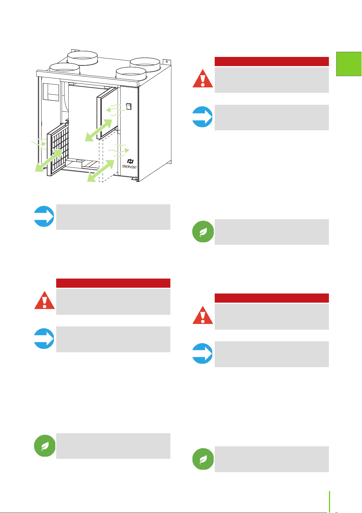
Replacing lters
Plain lter
To replace:
Replacing lters (generic view)
NOTE: Vacuum the inside of the unit for better
performance and cleaner indoor air.
Bag lter
DANGER
DANGER: Before opening the service hatch,
always make sure that the unit’s supply voltage
is switched o.
NOTE: For LTR-series units: The power cuts o
when the service hatch is opened.
1. Open the service hatch.
2. Remove the lter from the ventilation device.
3. Remove the lter fabric from the frame.
4. Replace the lter fabric with a new one.
5. Insert the lter back into the unit so that the
support grid faces the heat recovery wheel.
6. Close the service hatch properly.
7. Switch the power on.
TIP: Replace only the fabric part of the plain
lter. Reuse the metal frame with a clean lter.
The lter fabric can be disposed of along with
mixed waste.
EN
To replace:
DANGER
DANGER: Before opening the service hatch,
always make sure that the unit’s supply voltage
is switched o.
NOTE: For LTR-series units: The power cuts o
when the service hatch is opened.
1. Open the service hatch.
2. Release the lter locking levers, if there are any.
3. Pull the old lter out of the unit.
4. Insert a new lter.
5. Close the lter locking levers, if there are any.
6. Close the service hatch properly.
7. Switch the power on.
TIP: Remove the metal frame from the used bag
lter and recycle it along with metal waste. The
lter fabric can be disposed of along with mixed
waste.
Pleated lter
To replace:
DANGER
DANGER: Before opening the service hatch,
always make sure that the unit’s supply voltage
is switched o.
NOTE: For LTR-series units: The power cuts o
when the service hatch is opened.
1. Open the service hatch.
2. Remove the lter from the ventilation device.
3. Insert the new lter.
• Pay attention to the arrow on the lter
showing the airow through the lter.
4. Close the service hatch properly.
5. Switch the power on.
TIP: The lter can be disposed of along with
mixed waste.
33Installation instructions
Page 34

Fans
Inspecting
Cleaning
To clean:
To inspect:
DANGER
DANGER: Before opening the service hatch,
always make sure that the unit’s supply voltage
is switched o.
1. Inspect the cleanness of the fans visually when
changing the lters.
• If they look dirty, clean them.
TIP: Vacuum the inside of the unit for better
performance and cleaner indoor air.
Cleaning
To clean:
DANGER
DANGER: Before opening the service hatch,
always make sure that the unit’s supply voltage
is switched o.
DANGER
DANGER: Before opening the service hatch,
always make sure that the unit’s supply voltage
is switched o.
1. Remove the heat exchanger from the unit.
2. Wash the heat exchanger with water and neutral
detergent or use pressurized air.
WARNING
WARNING: Do not submerge the heat
exchanger in water. The electric motor inside the
exchanger must not get wet.
WARNING
WARNING: The use of a pressure washer is
strictly forbidden.
3. Dry the heat exchanger properly.
4. Place the heat exchanger back into the unit.
5. Start the unit up to verify the rotation.
6. Close the service hatch.
1. Remove the fans from the unit.
2. Clean the fans with a toothbrush or pressurized air.
• Do not disturb the balancing weights on the
fan blades.
3. Place the fans back into the unit.
When restarting the unit after cleaning, make sure that
the heat exchanger wheel and the fans turn freely.
Heat exchanger
Inspecting
To inspect:
1. Check the cleanness of the heat exchanger visually
when changing the lters.
• If it looks dirty, clean it.
TIP: Vacuum the inside of the unit for better
performance and cleaner indoor air.
When restarting the unit after cleaning, make sure that
the heat exchanger wheel turns freely.
Replacing heat exchanger belt
If the heat exchanger has stopped rotating, the reason
for it may be a broken drive belt. Check the condition of
the belt from the round opening at the front of the heat
exchanger. There is one spare belt attached to all heat
exchangers.
NOTE: Visit the HelpCenter on our webpage
www.enervent. for videos showing the
maintenance tasks.
To replace:
DANGER
DANGER: Turn o the ventilation unit by
switching o the main power supply, by
removing the fuse or by disconnecting the wall
plug.
34
Page 35

1. Detach the bayonet connector from the socket.
2. Remove the heat exchanger from the unit carefully.
3. Unscrew the six screws on the heat exchanger
maintenance hatch lid at the front side of the heat
exchanger.
4. Open the maintenance hatch with the help of a at
tool.
• Use for example a Stanley knife.
5. Pull o the broken heat exchanger belt.
6. Inspect the belt wheel to make sure it is
undamaged, in its place and rotating properly.
7. Clean the heat exchanger and the belt wheel.
• Use water and neutral detergent with a soft,
lint-free cloth.
• Rotate the heat exchanger to make sure
everything gets cleaned.
• Make sure that the heat exchanger is rotating
freely, without excessive force. You should be
able to rotate the heat exchanger with only
one nger.
9. Unscrew the hexagonal screw of the axle in the
middle of the U-beam and remove the beam.
10. Slide the new belt inside around the heat
exchanger through the opening in the casing and
the gasket.
11. Rotate the heat exchanger to get the belt properly
in place.
12. Replace the U-beam and reattach the axle and
U-beam screws.
13. Go through the new belt with the cleaning cloth to
make sure it is free of dirt.
14. Pull the belt onto the belt wheel.
EN
Go to step 8 if a spare belt is not attached on your heat
exchanger.
• Pull the spare exchanger belt from the holders
by rotating the exchanger.
• Leave the holders on the heat exchanger.
8. Loosen the U-beam on one side of the heat
exchanger by removing the screws under the
U-beam rubber gasket.
15. Rotate the heat exchanger to see that the belt is in
its place and everything looks ne.
16. Vacuum clean the heat exchanger casing.
• Rotate the heat exchanger when you are
vacuuming to be sure to clean everywhere.
17. Close the maintenance hatch.
18. Add some silicone onto the rubber strips outside
the heat exchanger casing.
19. Place the heat exchanger back into the unit.
20. Reconnect the bayonet connector to the socket.
21. Reconnect the power.
22. Make sure the heat exchanger rotates.
35Installation instructions
Page 36

TECHNICAL INFORMATION AND ATTACHMENTS
Models with duct coils
Hydronic (water)
after-heating coil
Unit
Pinion eWind W VEAB CWW
Pinion eWind
E-CHG
Pingvin eWind
E-CG/CHG
Pingvin
eWind W
Pingvin
XL eWind
E-CG/CHG
Pingvin XL
eWind W
(LxDxH)
Duct connection
Ø mm
125-3-2,5
276x313x255 mm
Ø 125 mm
VEAB CWW
160-3-2,5
276x313x255 mm
Ø 160 mm
VEAB CWW
200-3-2,5
276x398x330 mm
Ø 200 mm
Hydronic (brine)
cooling coil
(LxDxH)
Duct connection
Ø mm
VEAB CWK
200-3-2,5-L/R
395x415x330 mm
Ø 200 mm
VEAB CWK
200-3-2,5-L/R
395x415x330 mm
Ø 200 mm
VEAB CWK
200-3-2,5-L/R
395x415x330 mm
Ø 200 mm
Right hand
/ left hand
change
No No TE10 supply air sensor
Yes Yes
Yes Yes
No No TE10 supply air sensor
Yes Yes
No No TE10 supply air sensor
Condensate drain
connection
G ½” external thread
G ½” external thread
G ½” external thread
External sensors
TE45 return water sensor
TE01 outside air sensor
TE10 supply air sensor (CG)
TE01 outside air sensor (CHG)
TE45 return water sensor
TE10 supply air sensor (CG)
TE01 outside air sensor (CHG)
TE45 return water sensor
Pandion eWind
E-CHG
Pelican eWind
E-CHG
Pegasos eWind
E-CHG
Pegasos XL
eWind E-CG
Pegasos XL
eWind E-CHG
LTR-2 eWind
E-CHG
LTR-3 eWind
E-CG/CHG
VEAB CWK
200-3-2,5-L/R
395x415x330 mm
Ø 200 mm
VEAB CWK
250-3-2,5-L/R
395x491x405 mm
Ø 250mm
VEAB CWK
400-3-2,5-L/R
450x715x529 mm
Ø 400 mm
VEAB CWK
315-3-2,5
276x560x504 mm
Ø 315 mm
VEAB CWK
400-3-2,5-L/R
450x715x529 mm
Ø 400 mm
VEAB CWK
200-3-2,5-L/R
395x415x330 mm
Ø 200 mm
VEAB CWK
200-3-2,5-L/R
395x415x330 mm
Ø 200 mm
Yes Yes
G ½” external thread
Yes Yes
G ½” external thread
Yes Yes
G ½” external thread
No Yes
G ½” external thread
Yes Yes
G ½” external thrEad
Yes Yes
G ½” external thread
Yes Yes
G ½” external thread
TE01 outside air sensor
TE01 outside air sensor
TE01 outside air sensor
TE10 supply air sensor
TE01 outside air sensor
TE01 outside air sensor
TE10 supply air sensor (CG)
TE01 outside air sensor (CHG)
36
Page 37

Hydronic (water)
after-heating coil
Unit
LTR-3 eWind W VEAB CWW
LTR-4 eWind
E-CHG
LTR-6 eWind
E-CHG
LTR-7-eWind
E-CG
LTR-7-eWind
E-CHG
LTR-7-XL eWind
E-CG
LTR-7-XL eWind
E-CHG
(LxDxH)
Duct connection
Ø mm
160-3-2,5
276x313x255 mm
Ø 160 mm
Hydronic (brine)
cooling coil
(LxDxH)
Duct connection
Ø mm
VEAB CWK
200-3-2,5-L/R
395x415x330 mm
Ø 200 mm
VEAB CWK
250-3-2,5-L/R
395x491x405 mm
Ø 250mm
VEAB CWK
250-3-2,5-L/R
395x491x405mm
Ø 250mm
VEAB CWK
400-3-2,5-L/R
450x715x529 mm
Ø 400mm
VEAB CWK 315-32,5 276x560x504
mm Ø 400mm
VEAB CWK
400-3-2,5-L/R
450x715x529 mm
Ø 400mm
Right hand
/ left hand
change
No No TE10 supply air sensor
Yes Yes
Yes Yes
Yes Yes
Yes Yes
No Yes
Yes Yes
Condensate drain
connection
G ½” external thread
G ½” external thread
G ½” external thread
G ½” external thread
G ½” external thread
G ½” external thread
External sensors
TE45 return water sensor
TE01 outside air sensor
TE01 outside air sensor
TE10 supply air sensor
TE01 outside air sensor
TE10 supply air sensor (CG)
TE01 outside air sensor (CHG)
EN
CHG Pre-heating and pre-cooling coils
These coils are installed in the outside air duct (before the ventilation unit).
Denition CHG 200 CHG 250 CHG 400
Coil type VEAB CWK 200-3-2,5-L/R VEAB CWK 250-3-2,5-L/R VEAB CWK 400-3-2,5-L/R
Product code.
Suits listed Enervent units
(NOTE It is possible to use a
bigger coils than listed here)
Coil duct connection. Ø 200 mm Ø 250 mm Ø 400 mm
Coil outer dimensions and
weight dry/with uid.
Filter (plain lter)
Fluid pipe connections
Condense water drain
(underpressure)
Valve and valve actuator.
Additional outside air sensor 1 pcs 5 m sensor 1 pcs 5 m sensor 1 pcs 5 m sensor
L: K930040501V (left)
R: K930040501 (right)
Pinion, Pingvin, Pingvin XL,
Pandion, LTR-2, LTR-3, LTR-4
L 395 x H 330 x D 415 mm,
10/11 kg
1 pcs, ltering class G3.
379 x 296 x 13 mm
Spare lter package, 6 pcs
lters (no mesh).
22 mm
½ ”, must be equipped with
water trap.
Belimo ”R313” (R3015-4-S1),
3-way, kvs 4, DN 15
TR24-SR, 0-10V
L: K930040502V (left)
R: K930040502 (right)
Pelican, LTR-6 Pegasos, LTR-7
L 395 x H 405 x D 491 mm,
12/13,5 kg
1 pcs, ltering class G3
454 x 372 x 13 mm
Spare lter package, 6 pcs
lters (no mesh).
22 mm
½ ”, must be equipped with
water trap.
Belimo ”R317” (R3020-4-S2),
3-way, kvs 4, DN 20
HRYD24-SR, 0-10V
L: K930040503V (left)
R: K930040503 (right)
L 450 x H 529 x D 715 mm,
22/24,7 kg
1 pcs, ltering class G3
679 x 472 x 13 mm
Spare lter package, 6 pcs
lters (no mesh).
22mm
½ ”, must be equipped with
water trap.
Belimo ”R322” (R3025-6P3-S2),
3-way, kvs 6,3, DN 25
HRYD24-SR, 0-10V
37Installation instructions
Page 38

CHG Left-handed coil
Left-handed coil
stainless steel
Right-handed coil
Top
Rear wall
Bottom
Air ow to the left
Maintenance
door
Quick-release fastener (2 pcs)
Air ow
Condensation-water
outlet G½"
Condensation-water
outlet G½"
Coil
Drip water reservoir,
stainless steel
Filter rail
CHG Right-handed coil
Top
Quick-release
fastener (2 pcs)
Bottom
Air ow to the right
Condensation-water-insulated on the top, bottom,
on the rear wall and behind the maintenance door.
Maintenance
door
Quick-release fastener (2 pcs)
Condensationwater outlet G½"
Air ow
38
Filter rail
Drip-water reservoir
Coil
Quick-release
fastener (2 pcs)
Condensation-water-insulated on the top, bottom,
on the rear wall and behind the maintenance door.
Condensationwater outlet G½"
Page 39

List of extra equipment
EXTRA EQUIPMENT AVAILABLE
Code Explanation
K58 004 0001 eWind control panel package.
The package includes the control panel, a surface mounted junction box, and 10 m cable.
K93 003 0004 CO2 carbon dioxide transmitter for installation on the wall 0-10V / 24V
M23 010 0007 Built-in CO2 carbon dioxide sensor T8031
K91 103 0022 CO carbon monoxide sensor
K93 003 0006 %RH humidity transmitter for installation on the wall 0-10V / 24V
M23 011 0002 % RH humidity transmitter for installation in the duct KLK 100
K93 003 0008 Push button for activating over pressure/boosting
K93 003 0029 KNX gateway
K93 014 0004 Damper Ø 125 mm (without isolation, tightness class 3)
K93 002 0001 Damper Ø 160 mm (without isolation, tightness class 3)
K93 002 0002 Damper Ø 200 mm (without isolation, tightness class 3)
K93 002 0003 Damper Ø 250 mm (without isolation, tightness class 3)
K93 002 0004 Damper motor with spring return 230 VAC, 4 Nm
EN
39Installation instructions
Page 40

Troubleshooting
Alarm Description
FILS Service
reminder.
Err Sensor
malfunction.
- - - - Downloading eWind panel is
oFFE Stop mode. Ventilation o. Ventilation unit is
AL1 Water heater
coil in danger
of freezing.
AL2 Supply air
after HRW is
cold.
AL3 Supply air
cold.
AL4 Supply fan
failure.
AL5 Extract fan
failure.
Alarm
limit
4 or 6
months
+8 °C Supply air
+5 °C Supply air
+10 °C Supply air
Symptoms Possible reason Action Notes
cold.
cold.
cold.
No Supply air. Supply air fan has stopped. Repair or change the
No Extract air. Extract air fan has stopped. Repair or change the
Time for regular
maintenance.
A sensor is short- or open
circuited.
downloading data from
eWind main board.
commanded to stop mode
by an external control
system.
Water coil has frozen / is
about to freeze:
• Circulation pump has
stopped.
• Heat exchanger is not
rotating.
• Actuator of the water coil’s
control valve is faulty.
• Extract fan has stopped.
Heat exchanger is not
rotating:
• Drive belt is broken.
• Drive belt is slipping.
• Heat exchanger motor has
broken down.
Extract fan has stopped. Replace the fan.
Extract lter is blocked. Replace lter.
Ventilation is adjusted
incorrectly / not adjusted
at all.
Heat insulation for the
ducts is inadequate.
Ventilation unit fan speed is
incorrect.
Change lters.
Inspect ventilation unit.
Clean as needed.
Look for damages.
Check the connections
and wiring of sensors
Normal at start-up.
Otherwise check the
eWind connection cable.
Restart the pump.
Replace the motor or the
belt.
Replace the actuator.
Find out why / replace
the fan.
Replace the drive belt.
Clean or change the belt
and the heat exchanger.
Replace the heat
exchanger motor.
Readjust/adjust
ventilation according
to the ventilation
system design, using
appropriate measuring
tools.
Check the thickness of
the insulation in supply
and extract air ducts and
add insulation, if needed.
Always use the fan
speed specied by
the ventilation system
designer (even in winter)
supply fan.
extract fan
Press any
button for 5
seconds to
acknowledge
The unit will
not start before
the alarm
condition has
been removed
and the alarm
acknowledged
by pressing
any button on
the operating
panel.
The ventilation
unit enters the
malfunction
status, which
means that
the fans are
at minimum
speed.
The alarm is
automatically
acknowledged
after the fault
condition is
removed.
The unit will
not start before
the alarm
condition has
been removed
and the alarm
acknowledged
by pressing
any button on
the operating
panel.
40
Page 41

Alarm Description
AL6 Extract air
cold.
Alarm
limit
+10 °C Supply air
Symptoms Possible reason Action Notes
cold.
Indoor temperature is low. Rise the indoor
Extract air duct heat
insulation is insucient.
Ventilation unit service
hatch is open.
TE30 temperature sensor is
faulty.
temperature.
Check the insulation
of the ducts and add
insulation if needed.
Close the service hatch.
Repair or change the
sensor.
The ventilation
unit enters the
malfunction
status, which
means that
the fans are
at minimum
speed.
The alarm is
automatically
acknowledged
after the fault
condition is
removed.
EN
AL7 Supply air hot.
Fire hazard.
AL8 Electric after-
heater or
pre-heater
overheating.
+55 °C Supply air hot. Fire hazard. Check for any heat
Electrical after-heater is
malfunctioning.
Water after-heater valve
actuator is malfunctioning.
TE10 temperature sensor is
faulty.
Supply air hot. Electric pre- or after-heater
is not functioning:
• Overheating protector has
tripped.
• Supply air fan has stopped.
• Supply air lter is blocked.
• Outside air grating is
blocked.
• Controller card of heater is
broken.
• Heater is broken.
sources.
Repair or replace the
electrical after-heater.
Repair or replace the
valve actuator.
Repair or replace the
temperature sensor.
Find out the reason
for overheating and
acknowledge the error
message.
Find out reason / replace
the fan.
Replace the lter.
Clean the grating.
Remove possible
mosquito net.
Replace the controller
card.
Replace the heater.
The unit will
not start before
the alarm
condition has
been removed
and the
ventilation unit
restarted.
41Installation instructions
Page 42

Models and components
*HVAC planner denes the size of the circulation pump
Water-to-air
after-heating*
eWind
Model
control
system
with
eWind
No afterheating
/
-cooling
Built-in
electrical
afterheating
Built-in Duct coil Built-in Duct coil Duct coil
panel
eWind panel
set
Components
included in
the delivery
Freeze
protection
system,
2-way
valve,
valve
actuator,
relay
control
for pump
Duct coil,
freeze
protection
system,
2-way
valve, valve
actuator,
duct sensor,
relay control
for pump
Pinion eWind E X X
Pinion eWind W X X
Pinion eWind
E-CHG
PinioneWind
E-AGH
Pingvin eWind
E
Pingvin eWind
W
Pingvin eWind
E-CG
Pingvin eWind
E-CHG
Pingvin eWind
E-AGH
Pingvin XL
eWind E
Pingvin XL
eWind W
Pingvin XL
eWind E-CG
Pingvin XL
eWind E-CHG
Pingvin XL
eWind E-AGH
Pandion eWind
E
Pandion eWind
W
Pandion eWind
E-CG
Pandion eWind
E-CHG
Pandion eWind
E-AGH
X X X
X X X
X X
X X
X X X
X X X
X X X
X X
X X
X X X
X X X
X X X
X X
X X
X X X
X X X
X X X
Pelican eWind E X X
Pelican eWind
W
X X
Liquid circulation
cooling
(geo-cooling)*
3-way
valve, valve
actuator,
relay control
for pump
Duct coil
for cooling,
3-way
valve, valve
actuator,
relay
control for
pump, duct
sensor
Liquid
circulation
precooling/
heating
(CHG)*
Duct coil,
3-way
valve, valve
actuator,
relay control
for pump,
duct sensor
Air –
ground
heat
exchanger
(AGH)
Ground
ducting
not
available
from
Enervent
Outdoor air
sensor, relay
control for
changeover
damper
42
Page 43

Water-to-air
after-heating*
Liquid circulation
cooling
(geo-cooling)*
Liquid
circulation
precooling/
heating
(CHG)*
Air –
ground
heat
exchanger
(AGH)
EN
eWind
control
Model
Pelican eWind
E-CG
Pelican eWind
E-CHG
Pelican eWind
E-AGH
Pegasos eWind
E
Pegasos eWind
W
Pegasos eWind
E-CG
Pegasos eWind
E-CHG
Pegasos eWind
E-AHG
Pegasos XL
eWind E
Pegasos XL
eWind W
Pegasos XL
eWind E-CG
Pegasos XL
eWind E-CHG
Pegasos XL
eWind E-AGH
LTR-2 eWind E X X
LTR-2 eWind W X X
LTR-2 eWind
E-CHG
LTR-2 eWind
E-AGH
LTR-3 eWind E X X
LTR-3 eWind W X X
LTR-3 eWind
E-CG
LTR-3 eWind
E-CHG
LTR-3 eWind
E-AGH
LTR-4 eWind E X X
LTR-4 eWind W X X
LTR-4 eWind
E-CG
LTR-4 eWind
E-CHG
LTR-4 eWind
E-AGH
LTR-6-190
eWind E
system
with
eWind
panel
X X X
X X X
X X X
X X
X X
X X X
X X X
X X X
X X
X X
X X X
X X X
X X X
X X X
X X X
X X X
X X X
X X X
X X X
X X X
X X X
X X
No afterheating
/
-cooling
Built-in
electrical
afterheating
Built-in Duct coil Built-in Duct coil Duct coil
Ground
ducting
not
available
from
Enervent
43Installation instructions
Page 44

Water-to-air
after-heating*
Liquid circulation
cooling
(geo-cooling)*
Liquid
circulation
precooling/
heating
(CHG)*
Air –
ground
heat
exchanger
(AGH)
eWind
Model
control
system
with
eWind
No afterheating
/
-cooling
Built-in
electrical
afterheating
Built-in Duct coil Built-in Duct coil Duct coil
panel
LTR-6-190
eWind W
LTR-6-190
eWind E-CG
LTR-6-190
eWind E-CHG
LTR-6-190
eWind E-AGH
X X
X X X
X X X
X X X
LTR-7 eWind E X X
LTR-7 eWind W X X
LTR-7 eWind
E-CG
LTR-7 eWind
E-CHG
LTR-7 eWind
E-AGH
LTR-7 XL eWind
E
LTR-7 XL eWind
W
LTR-7 XL eWind
E-CG
LTR-7 XL eWind
E-CHG
LTR-7 XL eWind
E-AGH
X X X
X X X
X X X
X X
X X
X X X
X X X
X X X
Ground
ducting
not
available
from
Enervent
Technical features
Technical features are subject to change without prior notice. The declared AHU performance values are indicative
only. The performance of a given AHU under certain conditions must be checked from the Energy Optimizer
calculation program on the Ensto Enervent web site.
PINION, PINGVIN, PINGVIN XL, PANDION, PELICAN, PEGASOS, PEGASOS XL
UNIT PINION PINGVIN PINGVIN XL PANDION PELICAN PEGASOS PEGASOS XL
Width
Depth
Height
Weight 53 kg 50 kg 63 kg 90 kg 125 kg 203 kg 203 kg
Duct size Ø 125 mm Ø 160 mm Ø 160 mm Ø 160 mm Ø 200 mm Ø 250 mm Ø 250 mm
EC fans supply
and extract
Control card
5x20 mm
Glass tube fuse
Heat exchanger
motor with heat
protection
44
589 mm
320 mm
630 mm
118 W /
1,0 A
T0,8 A T0,8 A T0,8 A T0,8 A T0,8 A T0,8 A T0,8 A
5 W, 0.04 A 5 W, 0.04 A 5 W, 0.04 A 5 W, 0.04 A 5 W, 0.04 A 5 W, 0.04 A 5 W, 0.04 A
580 mm
500 mm
540 mm
118 W /
1,0 A
780 mm
555 mm
540 mm
163 W /
1,3 A
785 mm
543 mm
895 mm
163 W /
1,3 A
998 mm
590 mm
1 270 mm
170 W /
1,22 A
1 250 mm
677 mm
1 400 mm
520 W /
3,15 A
1 250 mm
677 mm
1 400 mm
545 W /
3,5 A
Page 45

PINION, PINGVIN, PINGVIN XL, PANDION, PELICAN, PEGASOS, PEGASOS XL
UNIT PINION PINGVIN PINGVIN XL PANDION PELICAN PEGASOS PEGASOS XL
Power of standard
electrical
afterheater coil
Power of optional
E-models
electrical
afterheater coil
Mains supply 230 V~/
Hydronic
afterheater
location
35/25°C total coil
W-models
power
30/20°C total coil
power
60/40°C total coil
power
Mains supply 230 V~/
Pipe connection 10 mm 10 mm 10 mm 15 mm 15 mm 28 mm 28 mm
Water ow 0,03 l/s 0,04 l/s 0,03 l/s 0,07 l/s 0,08 l/s 0,15 l/s 0,19 l/s
Water system
pressure loss
Kvs value of valve 0,63 0,63 1,0 1,0 1,6 4,0 4,0
Valve connection DN15 15 15 15 15 15 15
800 W 400 W 800 W 800 W 2 000 W 4 000 W 4 000 W
- 800 W - - 4 000 W 6 000 W 6 000 W
50 Hz
10 A
In duct In duct In duct Built-in Built-in Built-in Built-in
1,2 kW* 1,5 kW* 2,5 kW* 2,6 kW - 6,4 kW* 7,7 kW*
- 1,3 kW - 2,8 kW* 3,2 kW* - -
0.9 kW 2,0 kW 2,7 kW 3,0 kW 3,5 kW 6,2 kW 6,7 kW
50 Hz
10 A
4 kPa 10,3 kPa 5,9 kPa 6,6 kPa 9,2 kPa 3,3 kPa 3,3 kPa
230 V~/
50 Hz
10 A
230 V~/
50 Hz
10 A
230 V~/
50 Hz
10 A
230 V~/
50 Hz
10 A
230 V~/
50 Hz
10 A
230 V~/
50 Hz
10 A
230 V~/
50 Hz
16 A
230 V~/
50 Hz
10 A
400 V 3~/
50 Hz
3x16 A
230 V~/
50 Hz
10 A
400 V 3~/
50 Hz
3x16 A
230 V~/
50 Hz
10 A
EN
Dimensions of
duct coils
(w x h x l) mm
Cooling (CG) coil
location
Total coil power - - 1.2 kW 1.5 kW
CG-models
Pipe connection - - 22 mm 15 mm
Brine ow - - 0.06 l/s 0.08 l/s
Water system
pressure loss
Kvs value of valve - - 2.6 1.6 4.0 4.0 6.3
Valve connection DN- - 15 15 15 20 25
Dimensions of
duct coil (w x h x
l) mm
313x255x276
Ø 125 mm
- - In duct Built in Built-in Built-in In duct
- - 7.9 kPa 1.5 kPa
- - 415×330×395
313x255x276
Ø 160 mm
398×330×276
Ø 200 mm
Ø 200 mm
- - - -
(built-in)*
1.2 kW (duct)
(built-in)*
22 mm (duct)
(built-in)*
0.07 l/s (duct)
(built-in)*
7.7 kPa (duct)
415x330x395
Ø 200 mm
1.7 kW 3.2 kW 3.5 kW
15 mm 28 mm 22 mm
0.09 l/s 0.16 l/s 0.17 l/s
2.0 kPa 3.4 kPa 8.5 kPa
- - 560x504x276
Ø 315 mm
45Installation instructions
Page 46
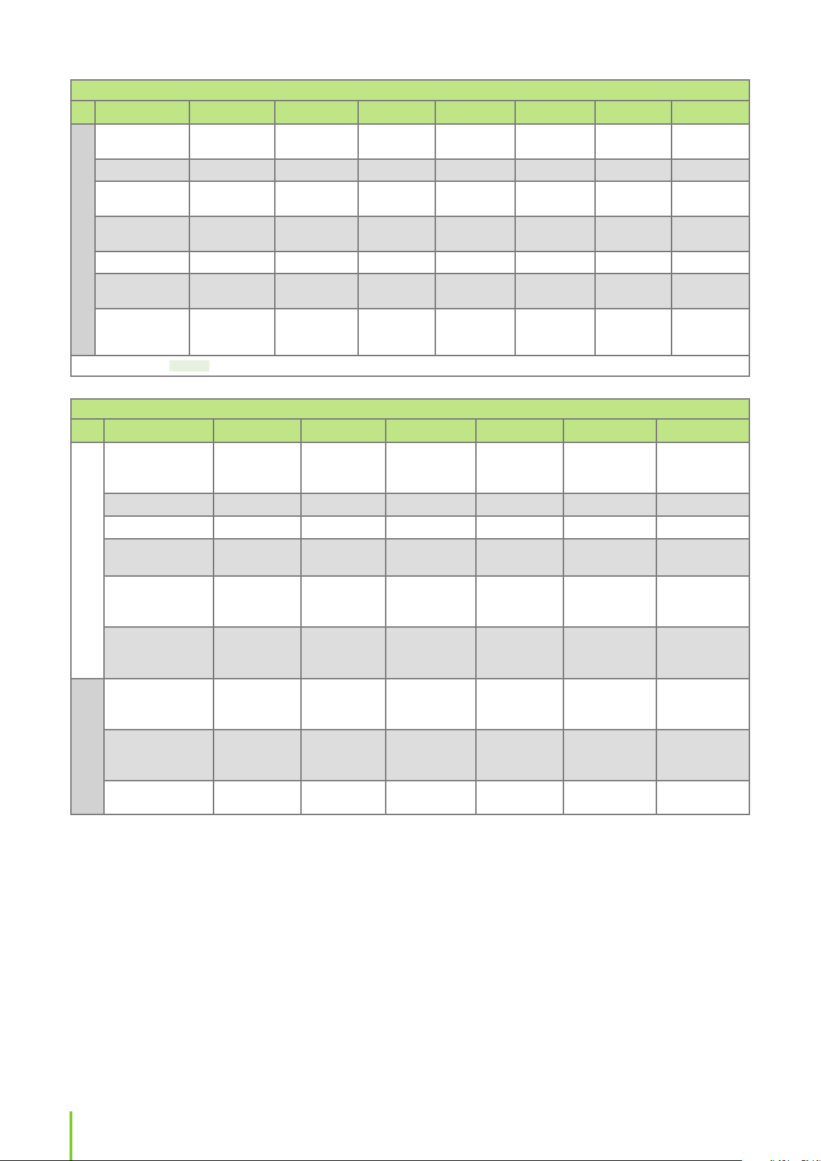
PINION, PINGVIN, PINGVIN XL, PANDION, PELICAN, PEGASOS, PEGASOS XL
UNIT PINION PINGVIN PINGVIN XL PANDION PELICAN PEGASOS PEGASOS XL
Total coil power
summer/winter
Pipe connection
Brine ow
CHG-models
summer/winter
Water system
pressure loss
Kvs value of valve
Valve connection
DN
Dimensions of
duct coil (w x h x
l) mm
0,8 / 1,5 kW 1.0 / 2.1 kW 1.3 / 3.1 kW 1.3 / 3.1 kW 1.9 / 4.5 kW 3.6 / 8.1 kW 3.8 / 8.9 kW
22 mm 22 mm 22 mm 22 mm 22 mm 22 mm 22 mm
0,05 / 0,11 l/s 0.05 / 0.11 l/s 0.07 / 0.17 l/s 0.07 / 0.17 l/s 0.10 / 0.24 l/s 0.19 / 0.43 l/s 0.2 / 0.47 l/s
3,5 / 11 kPa 4.2 / 12.2 kPa 5.7 / 32.5 kPa 5.7 / 32.5 kPa 5.7 / 6.3 kPa 6.6 / 27.7 kPa 7.1 / 35.5 kPa
4,0 4.0 4.0 4.0 4.0 6.3 6.3
15 15 15 15 20 25 25
415x330x395
Ø 200 mm
415x330x395
Ø 200 mm
415x330x395
Ø 200 mm
415x330x395
Ø 200 mm
491x405x395
Ø 250 mm
715x529x450
Ø 400 mm
715x529x450
Ø 400 mm
* = standard coil = standard coil information
LTR-2, LTR-3, LTR-4, LTR 6, LTR 7, LTR-7-XL
UNIT: LTR-2 LTR-3 LTR-4 LTR-6 LTR-7 LTR-7-XL
Width
Depth
Height
Weight
Duct size
EC fans
972 mm
393 mm
362 mm
41 kg 52 kg 85 kg 96 kg 130 kg 130 kg
Ø 125 mm Ø 160 mm Ø 200 mm Ø 200 mm Ø 250 mm Ø 250 mm
118 W, 1.0 A 118 W, 1.0 A 163 W, 1.30 A 170 W, 1.22 A 520 W, 3.3 A 545 W, 3.5 A
833 mm
480 mm
510 mm
1455 mm
536 mm
594 mm
1 190 mm
660 mm
660 mm
1 510 mm
707 mm
720 mm
1 510 mm
707 mm
720 mm
supply and extract
Control card 5x20
T0.8 A T0.8 A T0.8 A T0.8 A T0.8 A T0.8 A
mm
Glass tube fuse
Heat exchanger
5 W, 0.04 A 5 W, 0.04 A 5 W, 0,04 A 5 W, 0.04 A 5 W, 0.04 A 5 W, 0.04 A
motor
with heat protection
Power of standard
400 W 500 W 800 W 2 000 W 4 000 W 4 000 W
electrical afterheater
coil
Power of optional
electrical afterheater
E-models
- 800 W - 4 000 W 6 000 W 6 000 W
coil
Mains supply
230 V~/50 Hz
10 A
230 V~/50 Hz
10 A
230V~/50 Hz
10 A
230 V~/50 Hz
16 A
400 V 3~/50 Hz
3x16 A
400 V 3~/50 Hz
3x16 A
46
Page 47

LTR-2, LTR-3, LTR-4, LTR 6, LTR 7, LTR-7-XL
UNIT: LTR-2 LTR-3 LTR-4 LTR-6 LTR-7 LTR-7-XL
Hydronic afterheater
location
35/25°C total coil
power
W-models
30/20°C total coil
power
60/40°C total coil
power
Mains supply
Pipe connection 15 mm 10 mm 15 mm 22 mm 22 mm 28 mm
Water ow 0.032 l/s 0.04 l/s 0.06 l/s 0.09 l/s 0.13 l/s 0.18 l/s
Water system
pressure loss
Kvs value of valve 0.63 0.63 1.0 1.6 2.5 4.0
Valve connection DN 15 15 15 15 15 15
Dimensions of duct
coils (w x h x l) mm
Cooling (CG) coil
location
Total coil power
Pipe connection
CG-models
Brine ow
Water system
pressure loss
Kvs value of valve
Valve connection DN
Dimensions of duct
coil (w x h x l) mm
Total coil power
summer/winter
Pipe connection
Brine ow
CHG-models
summer/winter
Water system
pressure loss
Kvs value of valve
Valve connection DN
Dimensions of duct
coil (w x h x l) mm
Built-in In duct Built-in Built-in Built-in Built-in
1.6 kW* 1.8 kW* - 3.7 kW* 5.3 kW* 7.4 kW*
- - 2.6 kW* 4.3 kW 6.3 kW 7.3 kW
1.7 kW 2.3 kW 2.6 kW 3.8 kW 7.1 kW 7.7 kW
230 V~/50 Hz
10 A
8.6 kPa 13.7 kPa 4.5 kPa 3.5 kPa 7.0 kPa 4.2 kPa
- 313x255x356
- In duct Built-in Built-in In duct In duct
- 1.0 kW 2.0 kW** 2.4 kW 2.1 kW 3.5 kW
- 22 mm 15 mm 22 mm 22 mm 22 mm
- 0.05 l/s 0.11 l/s** 0.12 l/s 0.11 l/s 0.17 l/s
- 6.3 kPa 16.5 kPa** 2.8 kPa 5.9 kPa 8.47 kPa
- 1.6 1.6 4.0 4.0 4.0
- 415x330x395
0.95 / 1.8 kW 1.1 / 2.6 kW 1.9 / 3.2 kW 2.3 / 4.7 kW 3.6 / 8.1 kW 3.8 / 8.9 kW
22 mm 22 mm 22 mm 22 mm 22 mm 22 mm
0.05 / 0.10 l/s 0.06 / 0.14 l/s 0.1 / 0.1 l/s 0.13 / 0.25 l/s 0.19 / 0.43 l/s 0.2 / 0.47 l/s
3.8 / 9.9 kPa 4.8 / 18.1 kPa 6.7 /7.8 kPa 7.6 / 32.9 kPa 6.6 / 27.7 kPa 7.1 / 35.5 kPa
4.0 4.0 4.0 4.0 6.3 6.3
15 15 20 20 25 25
415x330x395
Ø 200 mm
230 V~/50 Hz
10 A
Ø 160 mm
15 15 15 15 15
Ø 200 mm
415x330x395
Ø 200 mm
230V~/50 Hz
10 A
- - - -
- - 491x405x395
491x405x395
Ø 250 mm
230 V~/50 Hz
10 A
491x405x395
Ø 250 mm
230 V~/50 Hz
10 A
Ø 250 mm
715x529x450
Ø 400 mm
* = standard coil = standard coil information ** = 40% Ethylene-Glycol solution
EN
230 V~/50 Hz
10 A
560x504x276
Ø 315 mm
715x529x450
Ø 400 mm
47Installation instructions
Page 48

Dimensional drawings
Pinion right hand
48
Page 49

Pinion left hand
EN
49Installation instructions
Page 50

Pingvin right hand
50
Page 51

Pingvin left hand
EN
51Installation instructions
Page 52

Pingvin XL right hand
52
Page 53

Pingvin XL left hand
EN
53Installation instructions
Page 54

Pandion
54
Page 55

Pelican
EN
55Installation instructions
Page 56

Pegasos
56
Page 57

LTR 2
EN
57Installation instructions
Page 58

LTR 3
58
Page 59

LTR 4
EN
59Installation instructions
Page 60

LTR 6 25 mm
60
Page 61
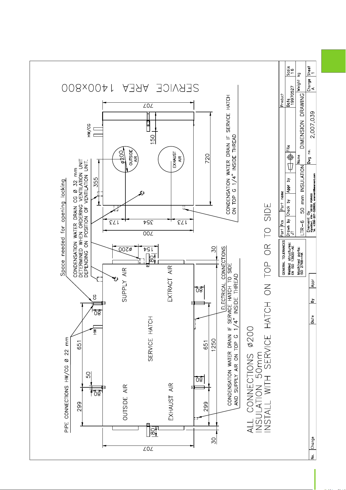
LTR 6 50 mm
EN
61Installation instructions
Page 62

LTR 7
62
Page 63

Wiring digrams
eWind basic wiring diagram
EN
63Installation instructions
Page 64

eWind basic wiring diagram Pingvin XL, Pegasos and LTR-7
64
Page 65
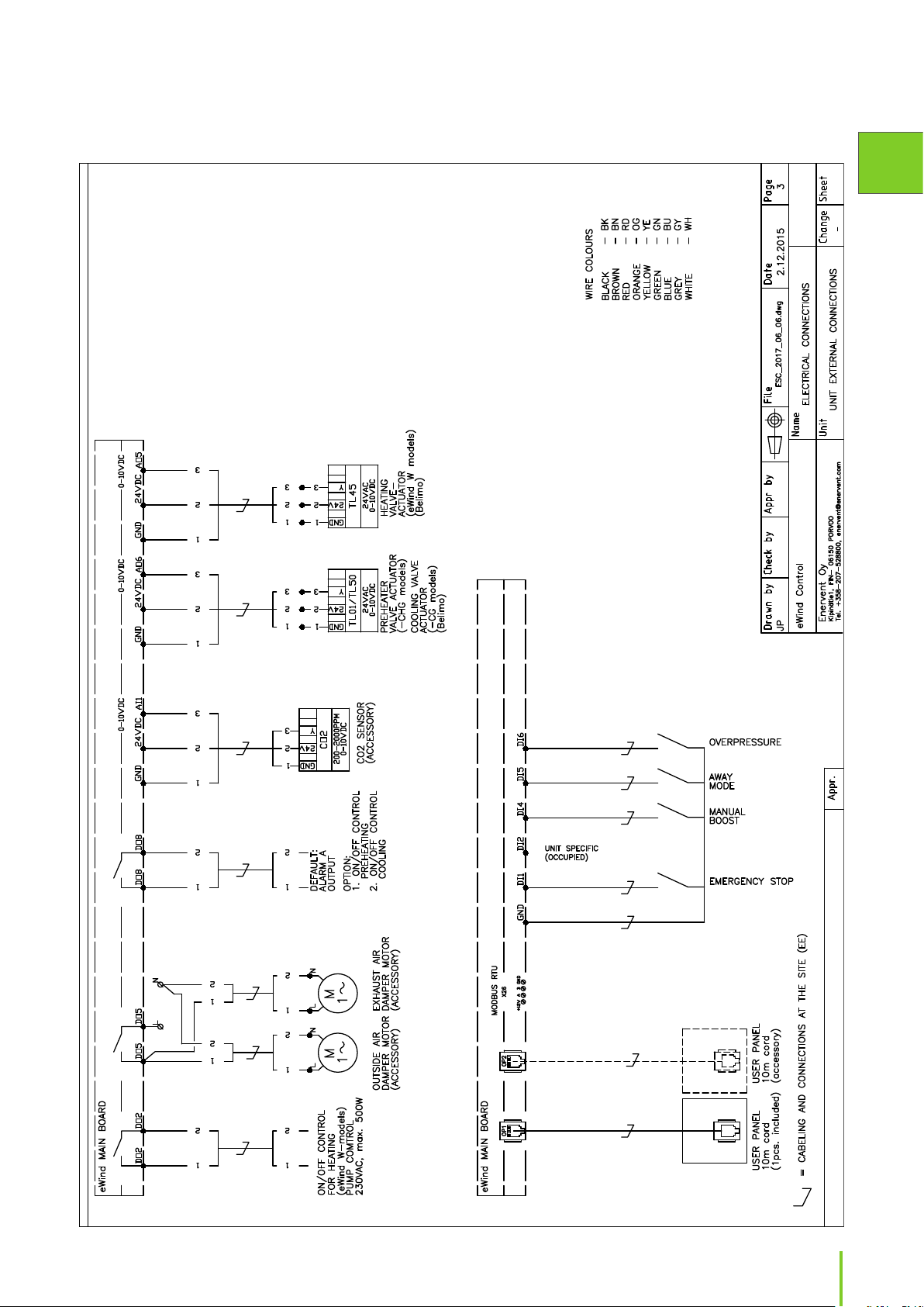
eWind basic external connections
EN
65Installation instructions
Page 66

eWind basic internal connections
66
Page 67

eWind electrical heater ≤ 2kW
EN
67Installation instructions
Page 68

eWind electrical heater > 2kW
68
Page 69

eWind external electrical heater
EN
69Installation instructions
Page 70

eWind electrical pre-heater
70
Page 71

eWind extractor hood connections
EN
71Installation instructions
Page 72

Principal diagrams
eWind HW principle scheme
ESW_PRINCIPLE_SCHEME.dwg
72
Page 73

eWind CG principle scheme 1
EN
73Installation instructions
Page 74

eWind CG principle scheme 2
74
Page 75

eWind CG principle scheme 3
EN
75Installation instructions
Page 76

eWind CG principle scheme 4
76
Page 77
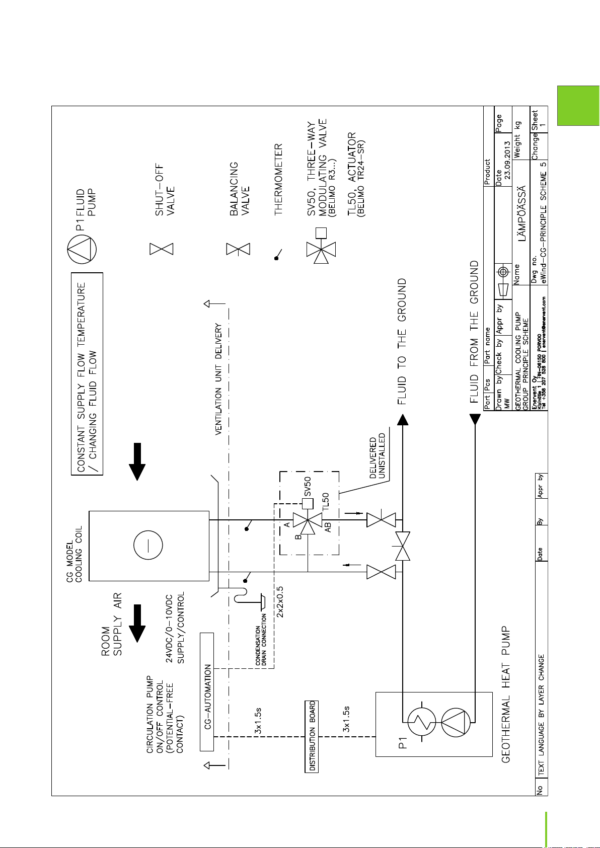
eWind CG principle scheme 5
EN
77Installation instructions
Page 78

eWind CG connections
78
Page 79

eWind CHG principle scheme ground loop
EN
ES_CHG_PERIAATEKAAVIO_MAASILMUKKA.dwg
79Installation instructions
Page 80

eWind CHG principle scheme heat exchanger
80
Page 81

eWind CW principle scheme
EN
81Installation instructions
Page 82

Control charts
Air handling unit, component catalog
Designation
OP20
TE01
TE05
Supply air, after heat recovery
TE10
RHT30
Extraxt air; temperature and humidity
TE32
SU1
SU30
LTO75
M75+SC75
TF10+M10+SC10
PF30+M30+SC30
SLP45
W45
TL45+SV45
Valve actuator + 2-way control valve
TL50+SV50
Valve actuator+ 3-way control valve
CG50
TE02
CO2
FG01
Fresh air dampers+Damper motor
FG39
Exhaust air dampers+Damper motor
eWind control charts component catalog
Alternatively F7
Alternatively F7
Technical data Note
Standard NTC-10
Equipment
Standard NTC-10
Standard NTC-10
Standard NTC-10
Standard Sender
EC motor, max effect 15 W
W-models Effect acc. to Unit size
Standard
Standard
Standard EC motor
W-models Kvs-value acc. to Unit size
E-models Effect acc. to Unit size
CG-models Kvs-value acc. to Unit size
Pushbutton
NTC-10
Optional equipment
Optional equipment
CG-models Effect acc. to Unit size
Optional equipment 200-2000ppm, 0-10Vdc
Models with preheating
Optional equipment
Control panel 1 pc standard delivery eWind delivery, contains cabel
Name
Supply air temperature
Fresh air temperature
82
Supply fan
Exhaust air temperature
Fresh air filter Standard Standard M5
Extract air filter Standard Standard M5
Rotating heat exchanger
HRW motor + control
Supply air reheater, electrical
Exhaust fan Standard EC motor
Supply air reheater, water
Supply air cooler
CO2-measurement
Extra time, switch
Preheated outdoor air
HS
Emergency stop Normally open (NO) as standard
HZ
Page 83

eWind E (ARCTIC)
eWind
ELECTRICAL
CABINET
EN
eWind_REV_A
E
>2kW
eWind E (ARCTIC)
ARCTIC
UNIT
83Installation instructions
Page 84

eWind W Pingvin, Pingvin XL, LTR-3
eWind
ELECTRICAL
CABINET
eWind_REV_A
eWind W
Pingvin, Pingvin XL, LTR-3
84
UNIT
Page 85

eWind W Pandion, Pelican, Pegasos, Pegasos XL, LTR-2, LTR-4, LTR-6, LTR-7, LTR-7 XL
eWind
ELECTRICAL
CABINET
EN
eWind_REV_A
eWind W Pandion, Pelican, Pegasos (XL)
LTR-2, LTR-4, LTR-6, LTR-7 (XL)
UNIT
85Installation instructions
Page 86

eWind E-CG Pingvin XL, Pegasos XL, LTR-3, LTR-7, LTR-7 XL
eWind
ELECTRICAL
CABINET
eWind_REV_A
E
>2kW
eWind E-CG Pingvin XL, Pegasos XL,
LTR-3, LTR-7, LTR-7 XL
86
UNIT
Page 87

eWind E-CG Pandion, Pelican, Pegasos, LTR-4, LTR-6
eWind
ELECTRICAL
CABINET
EN
eWind_REV_A
E
>2kW
eWind E-CG Pandion, Pelican, Pegasos,
LTR-4, LTR-6
UNIT
87Installation instructions
Page 88
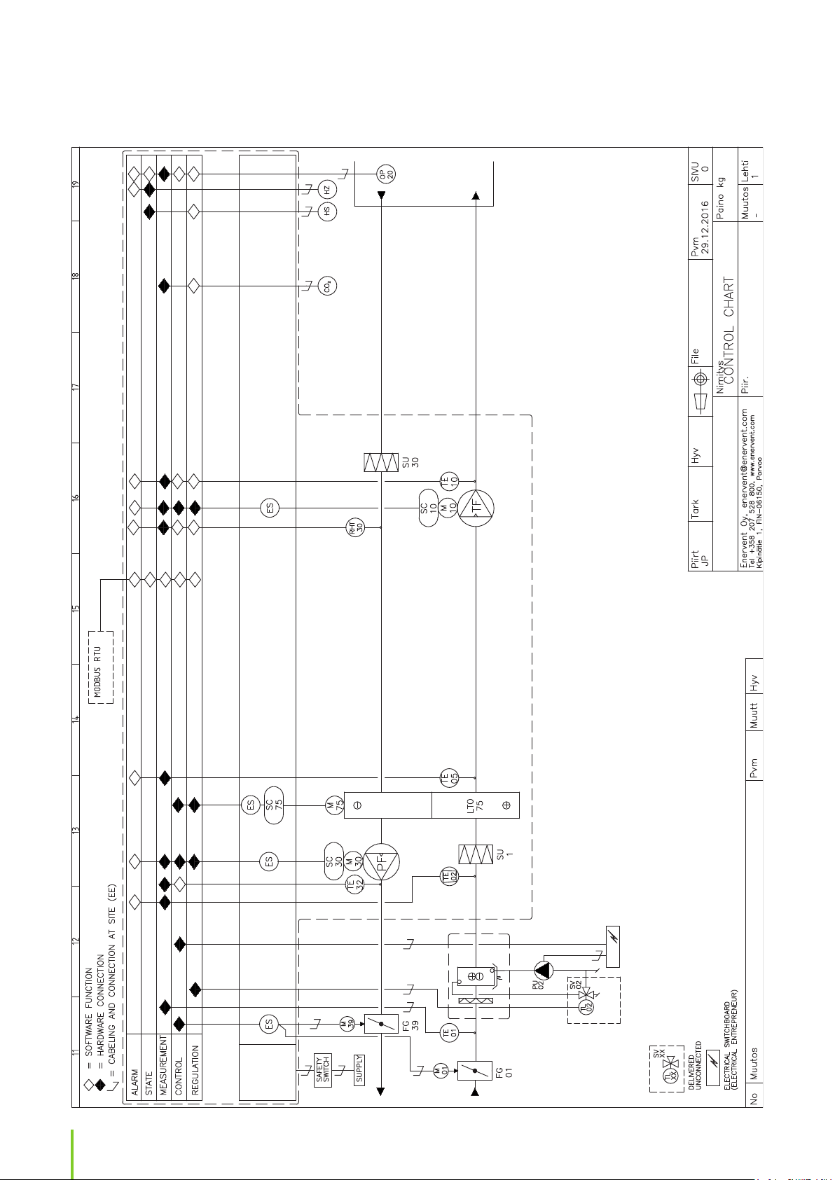
eWind CHG
eWind
ELECTRICAL
CABINET
eWind_REV_A
eWind CHG
88
CHG
UNIT
Page 89

eWind AGH
eWind
ELECTRICAL
CABINET
EN
eWind_REV_A
eWind AGH
M
02
FG
02
UNIT
89Installation instructions
Page 90

Room /measuring
point / oor
Raum / Etage
Supply air / Zuluft Extract air / Abluft
Terminal
device
Luftdurch-
lässe
Planned air
amount
Planierten
luftmengen
Measured
air amount
Gemesste
luftmengen
p Pa Setting
Anstellung
Terminal
device
Luftdurch-
lässe
Planned air
amount
Planierten
luftmengen
Measured
air amount
Gemesste
luftmengen
p Pa Setting
Anstellung
Lpa dB(A) Note! Achtung!
Total planned air amounts / Planierten luftmengen gesamt supply air / zuluft: extract air / abluft:
Total realized air amounts / Gemesste luftmengen gesamt supply air / zuluft: extract air / abluft:
Air amount / Luftmenge
Fanspeed+dierence/
Gebläse Geschwindgkeit+Abweichung
Home / zum Hause Away / Abwesend Boosting
Measuring instrument / Messinstrument:
Weather conditions / Wetterverhältnisse:
Underpressure in the building / Unterdruck des Gebäude: Pa
Company / Fachrma:
Performed by / Durchgeführt von:
90
Page 91

EU DECLARATION OF CONFORMITY
We declare that our products follows the provisions of low voltage directive LVD 2014/35/EU, electromagnetic
compatibility directive EMC 2014/30/EU, machine directive MD 2006/42/EC, radio equipment and telecommunications
terminal equipment directive R&TTE 1999/5/EC, ROHS II directive 2011/65/EU, battery directive 2013/56/EU and
waste electrical and electronic equipment directive WEEE 2012/19/EU.
EN
Manufacturer:
Manufacturer´s contact:
Description of the product:
Trade name of the product:
The products are in conformity with the following standards:
LVD EN 60335-1:2012/A11:2014
EN 62233:2008/AC:2008
EMC EN 61000-3-2:2014 and EN 61000-3-3:2013
EN 61000-6-1:2007 and EN 61000-6-3:2007/A1:2011/AC:2012
EN 55014-1:2006/A2:2011 and EN 55014-2:1997/A2:2008
R&TTE EN 62368-1:2014/AC:2015
MD EN ISO 12100:2010
Ensto Enervent Oy
Kipinätie 1, 06150 Porvoo, FINLAND, Tel +358 207 528 800, fax +358 207 528 844
enervent@enervent.com, www.enervent.com
Ventilation unit with heat recovery
Enervent® series:
Piccolo, Plaza, Pinion, Pingvin, Pingvin XL, Pingvin Kotilämpö, Pandion, Pandion
Twincoil, Pelican, Pelican HP, Pegasos, Pegasos XL, Pegasos HP, Pegasos
Twintropic, Pallas, Pallas HP, Liggolo, LTR-2, LTR-3, LTR-4, LTR-6, LTR-7, LTR-7
XL.
ROHS EN 50581:2012
The conformity of each manufactured product is taken care according our quality descriptions.
Product is CE-marked year 2016.
Porvoo 20th of April 2016
Enervent Oy
Tom Palmgren
Technology manager
91Installation instructions
Page 92

Representatives for the products outside of Finland
Country Contact information
Sweden Ventener Ab, Sweden, tlf. +46 (0)10-482 6551
Norway Exvent Ab, Gml. Ringeriksvei 125, 1356 BEKKESTUA, NORWAY, tel +47 95 49 67 43
Estonia As Comfort Ae, Jaama 1, 72712 PAIDE, ESTONIA, tel +372 38 49 430
Ireland Entropic Ltd., Unit 3, Block F, Maynooth Business Campus, Maynooth, Co. Kildare, IRELAND,
tel +353 64 34920
Germany
Austria M-Tec Mittermayr GmbH, 4122 ARNREIT, AUSTRIA, tel +43 7282 7009-0
Poland Ensiwent S.C., Baldram 9A, 82-500 Kwidzyn, POLAND
Switzerland Duc Lufttechnik GmbH, Mühlebachweg 9, 5620 BREMGARTEN, SWITZERLAND, tel +41 56 631 64 34
Russia « », . -, , 69, «» . 413,
. + 7 (812) 642-42-70
«», , . , (), 4807, .1,
9, . + 7 (495) 649-65-59
Denmark Covent EMJ, Donsvej 55, 6052 VIUF, DENMARK, tel +45 7556 1288
Belgium EUREKA CONFORT Belgium scrl, Avenue Comte Jean Dumonceau 23, 1390 GREZ-DOICEAU, BELGIUM,
tel +32 10 84 3333
France TecControl Save Energy, 12 rue Jean-Marie DAVID, 35740 PACE, Tel. +33 (0) 2 99 05 60 50
92
Page 93

EN
93Installation instructions
Page 94

94
Page 95

EN
95Installation instructions
Page 96
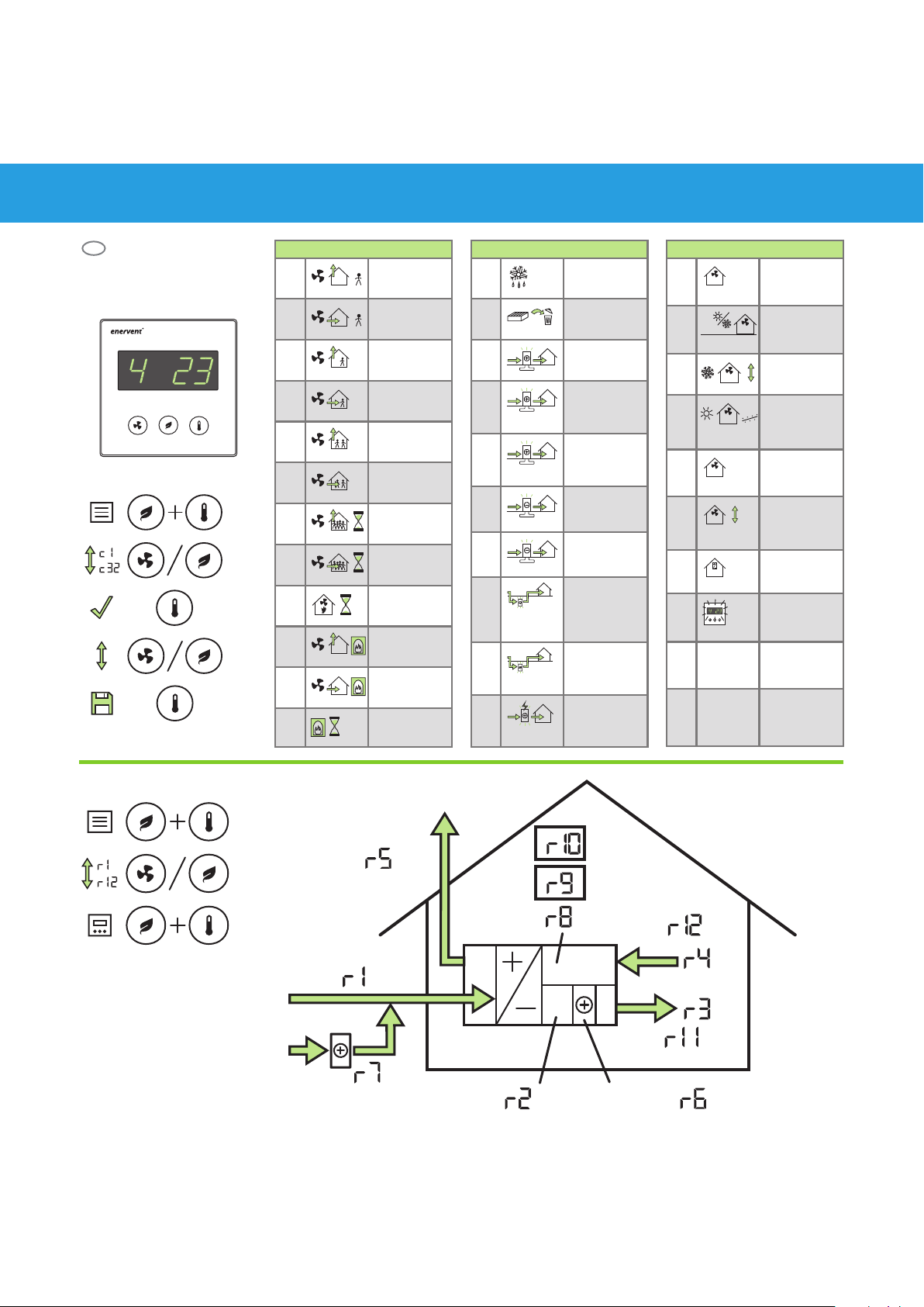
<˚C
>˚C
>˚C
˚C
Enervent eWind
ENG
Quick guide for contractor
Parameters (c)
c1 36%
(20-100%)
Parameters (c)
c13 oFF
(on / oFF)
Parameters (c)
c23
%RH
on
(on / oFF)
x 3
> 3 sec
c2 35%
c3 56%
c4 55%
c5 83%
c6 80%
c7 100% (20-
c8 100% (20-
c9 2 h
c10 30%
c11 50%
c12 10 min
(20-100%)
(20-100%)
(20-100%)
(20-100%)
(20-100%)
100%)
(120 min)
100%)
(120 min)
(1...4 h)
(20-100%)
(20-100%)
(0...15 min)
c14 4
c15 oFF
c16
c17
c18 on
c19
>˚C
c20
<˚C
c21
<˚C
c22
(4 / 6)
(on / oFF)
=> on,
TE01 < °C,
5°C (0…10°C)
=> o, TE01 >
(c16 + c17),
1°C (1…5°C)
on / oFF
=> on,
TE01 > °C, 17°C
=> on,
TE01 > °C,
20°C (15…25°C)
=> o, TE01 <
(c20 - c21),
2°C (1…5°C)
-15°C
(-10…-20°C)
c24
c25
c26
c27
%CO
c28
%CO
c29
%RH
c30 oFF
c31 ESC
Modbus
c32 Modbus 2
%RH
%RH
%RH
2
2
4°C
(-10…+10°C)
45%
(10...100%RH)
=>on, 48 h %RH
48 h
+ c26,
15% (5…30%)
oFF
(on / oFF)
CO=> on,
1000 ppm
(600...1200)
oFF
(on / oFF)
(on / oFF)
1
(1...99)
(1=9600,
2=19200,
3=115200)
x 2
%RH
˚C
˚C
RH30
%CO
%RH
2
η%
˚C
TE30
˚C
TE10
η%
TE32
TE01
˚C
TE02
Enervent Oy
Kipinätie 1
FIN-06150 Porvoo, Finland
Tel. +358 207 528 800
Fax. +358 207 528 844
enervent@enervent.com
www.enervent.com
TE05
˚C
W ˚C
TE45
 Loading...