


RM 36V/48V Series Solar Charge Controller
User’s Manual
【Notice】
Before operating the product, please read this User Manual carefully to
understand its correct usage. After reading it, please keep it properly for
future reference.
Warning
The input and output voltage of this equipment is the dangerous high voltage, which can endanger the
personal life. Please strictly follow all warns and operating instructions on the machine and in the Manual.
The professional maintenance personnel without authorization are not allowed to disassemble the outer cover
of the machine case of this equipment.
1. Please read this User Manual carefully before using the equipment and use it according to the
requirement of the User Manual.
2. During running of this equipment, please do not touch the power supply input and output wires to
avoid electric shock.
3. Please do not open the outer cover of the equipment without authorization, because there is the
danger of electric shock.
4. Please first turn off the switch of the solar polar plate and then the switch of the backup battery in
any emergency case.
5. You must ensure reliable earthing of the equipment before it is connected.
6. The backup battery pack should be kept away from the source of ignition and all electrical
equipment which can easily cause spark, to avoid danger or losses.
7. Please do not open or damage the backup battery. The leaked electrolyte is corrosive, which is
haRM-ful to personal health.
8. The backup batteries with different brands and different types require different charging voltages.
Please ensure that the charging voltage of the equipment matches the backup battery before using
them. In case of any doubt, please consult the manufacturer.
9. In case of any problems, please consult the professional personnel of the dealer or authorized
service shop, rather than solve it without authorization.
10. This equipment must be installed and maintained by professionals.
11. Please do not arbitrarily set up the parameters in the equipment menu, which should be set up by
the professional personnel or through consulting the manufacturer.
12. The change of the system configuration, structure and component will impact the equipment
perfoRM-ance. If you want to carry out such operation, please consult the manufacturer in
advance.
13. Please ensure that the temperature of the product returns to the noRM-al working temperature
range before using it. It is suggested to place the product within the working temperature range
for 24 hours before starting up.

Contents
Chapter 1 Overview ......................................................................................................................................... 1
1.1 Company Profile ................................................................................ ¡Error! Marcador no definido.
1.2 Product Introduction ............................................................................................................................ 1
1.2.1 Product Features ........................................................................................................................ 1
1.2.2Technical Index .......................................................................................................................... 2
Chapter 2 Basic principle and structure.........................................................................................................3
2.1 Stand-alone Principles .......................................................................................................................... 3
2.1.1 Block Diagram of the Operating Principles .............................................................................. 3
2.1.2 Operating Principles .................................................................................................................. 4
2.2 Structure of the Main Engine ............................................................................................................... 5
2.2.1 Outline Structure ....................................................................................................................... 5
2.2.2.1 Notes for Wiring ........................................................................................................ 7
2.2.2.2Diagram of the Amphenol Connector ......................................................................... 7
2.2.2.3 Use Operation Steps ................................................................................................... 8
2.2.3 Instruction about the Human-computer Interface of the LCD Display Panel ........................... 8
Chapter 3 Maintenance Instruction ............................................................................................................. 11
3.1 Common Faults and Troubleshooting Process ................................................................................... 11
3.1.1 Preventive Periodic Maintenance ............................................................................................ 11
3.1.2 Fault Maintenance Steps ......................................................................................................... 11
3.1.3 Maintenance Operation Steps ................................................................................................. 11
3.1.4 Maintenance of the Solar Cell Plate ........................................................................................ 12
3.1.5 Other Maintenance .................................................................................................................. 12
3.1.6 Diagnosis of the Common AbnoRM-ities ............................................................................... 12
Chapter 4 Transportation and Storage ........................................................................................................ 13
4.1 Transportation .................................................................................................................................... 13
4.2 Storage ............................................................................................................................................... 13
Dear customer, thank you very much for your use our company research and development
production RM- series solar controller..We sincerely hope our products can meet your needs, at
the same time also hope you can are proposed on the perfoRM-ance of the product more
valuable advice.We will continue to improve product quality.
The purpose of this manual is to provide detailed product infoRM-ation to the readers and
the controller operation and maintenance instructions.Please read this manual carefully before
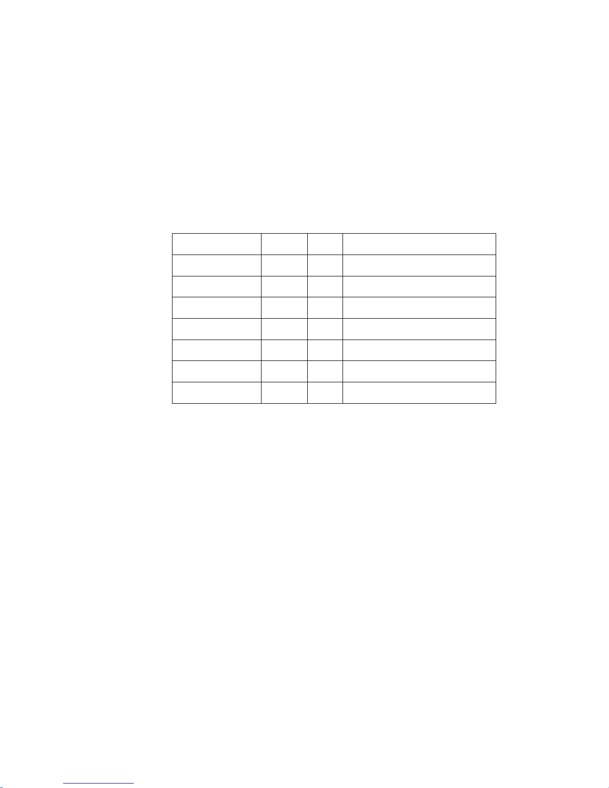
use! When you receive equipment, whether to comply with the following list, please check the
equipment and accessories . If found lost, please contact us as soon as possible.
title
quantity
unit
remark
Charge Controller
1
pcs
TeRM-inals
6
pcs
M4 Screw
4
pcs
For install the controller on the wall
Gallow pulley
4
pcs
For install the controller on the wall
User manual
1
pcs
warranty card
1
pcs
Temperature sensor
1
pcs
optional

User Manual of the RM 36V/48V Series of Solar Charge Controller
- 1 -
Chapter 1 Overview
1.1 Product Introduction
1.1.1 Product Features
Subdivision control of charging and discharging and intelligent battery management;
MPPT computing control and the follow-up accuracy reaches 99.5%;
Wall mounting type, front display and input and output wires at the bottom;
Pole sharing control mode and multichannel solar matrix input control;
Core technology of the intelligent MCU control and professional control computing to
achieve the intelligent control;
RS48-5 remote communication and data transmission;
Accurate measurement display of the photovoltaic generation and it can accurately
record the total photovoltaic generation;
Have the input anti-transposition protection/ undervoltage protection, overvoltage
protection, overtemperature protection, output overvoltage protection, input overcurrent
protection, output short-circuit protection, input and output anti-position protection,
battery undervoltage protection and so on;
LED visually displays various current infoRM-ation and the user can understand the
operating conditions of the system at any time;
Comprehensive LCD display interface and English menu display;
The user can set up the output voltage parameter and it has the function to save the
power failure;
Have the function to save the historic alaRM- records;
User Manual of the RM 36V/48V Series of Solar Charge Controller
- 2 -
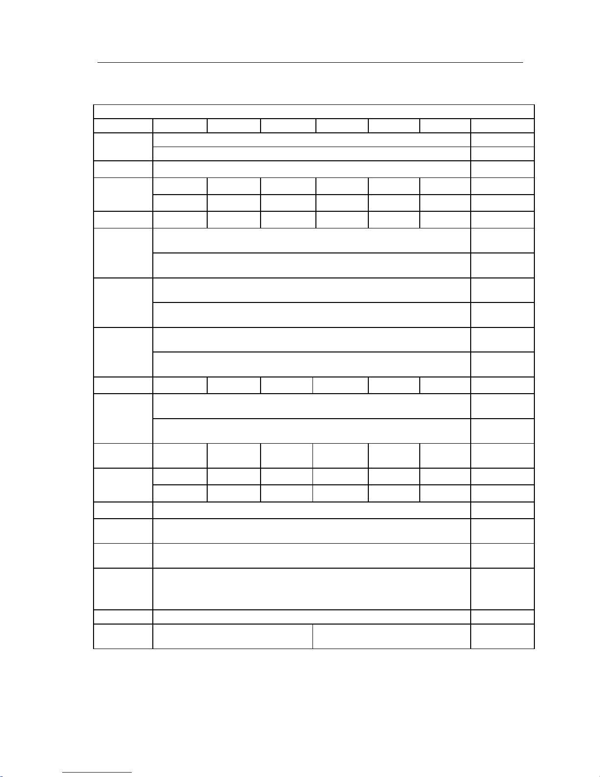
1.1.2Technical Index
Table 1-1 Main Technical Index of the RM 36V/48V Series
48V/36V System
Model
RM-60-36/48
RM-50-36/48
RM-40-36/48
RM-30-36/48
RM-20-36/48
RM-10-36/48
Remarks
Input working
voltage range
55V-150V (36V system)
70V-150V (48V system)
Maximum input
voltage
160V
Maximum input
power
2250W (36V
system)
1875W (36V
system)
1500W (36V
system)
1125W (36V
system)
750W (36V
system)
375W (36V
system)
3000W (48V
system)
2500W (48V
system)
2000W (48V
system)
1500W (48V
system)
1000W (48V
system)
500W (48V
system)
Maximum input
current
60A
50A
40A
30A
20A
10A
Floating charging
voltage
40.8V (36V system)
Can be set up
through the LCD
panel
54.4V (48V system)
Can be set up
through the LCD
panel
Equal charging
voltage
42.9V (36V system)
Can be set up
through the LCD
panel
57.2V (48V system)
Can be set up
through the LCD
panel
Charging
protection
voltage
43.8V (36V system)
Can be set up
through the LCD
panel
58.4V (48V system)
Can be set up
through the LCD
panel
Maximum
charging current
60A
50A
40A
30A
20A
10A
Discharging
protection
voltage
31.5V (36V system)
Can be set up
through the LCD
panel
42V (48V system)
Can be set up
through the LCD
panel
Maximum
discharging
current
60A
50A
40A
30A
20A
10A
Maximum load
power
2250W (36V
system)
1875W (36V
system)
1500W (36V
system)
1125W (36V
system)
750W (36V
system)
375W (36V
system)
3000W (48V
system)
2500W (48V
system)
2000W (48V
system)
1500W (48V
system)
1000W (48V
system)
500W (48V
system)
Conversion
efficiency
95%
Use ratio of the
photovoltaic
module
99%
Operating
environment
temperature
-20~+50 ℃
Operating
altitude
≤3,000
When the altitude
exceeds 3,000m,
1℃ should be
reduced for each
additional 200m.
Protection class
IP20
Dimension
(width*depth*hei
ght)
242.2×212×86.5mm
224×178×86mm
Including the
hanger width
The index specification will be subject to the change without prior notice.
User Manual of the RM 36V/48V Series of Solar Charge Controller
- 3 -
Chapter 2 Basic Principles and Structure
2.1 Stand-alone Principles
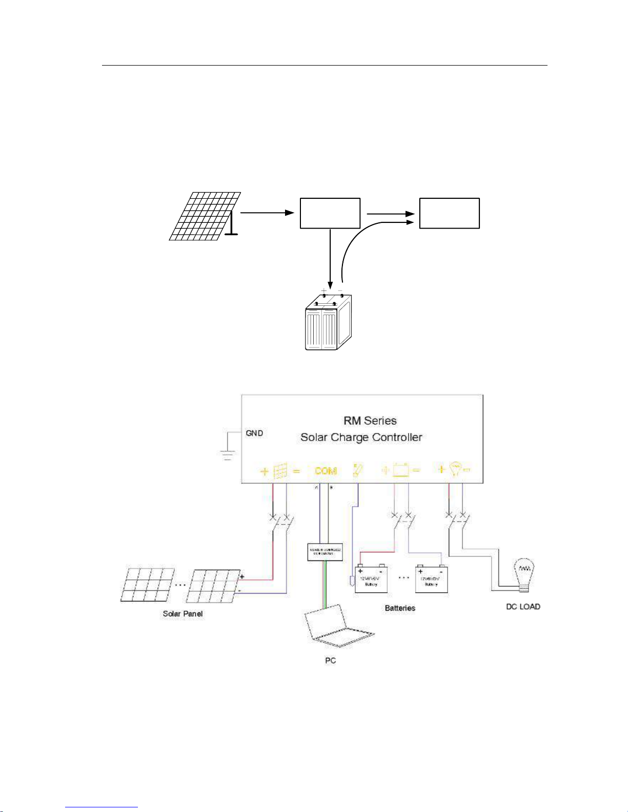
2.1.1 Block Diagram of the Operating Principles
Photovoltaic matrix
Backup battery pack
Solar photovoltaic
intelligent controller
DC equipment
Figure 2-1 Block Diagram of Operating Principles of Solar Charge Controller
Figure 2-2 Block Diagram of Operating Principles of the RM- Series

User Manual of the RM 36V/48V Series of Solar Charge Controller
- 4 -
2.1.2 Operating Principles
This product is the photovoltaic DC supply control system designed for the DC load a nd
front DC input part of the DC input inverter and its purpose is to achieve the input control
system composed of the solar matrix input and battery pack input and provide the DC load with
power through the management of the backup battery charging by the controller or provide the
AC load with power through inverter, thus completely and reasonably store and apply the solar
energy to reach the purpose of being green
and energy saving, which is designed for the power
supply of the communiction nor monitoring equipment in the remote areas. The
human-computer interface of this product can particularly display the operating parameters and
operating condition of all input modules, output real-time parameter, statistics of the
photovoltaic generation, various protection functions, LED indicator light alaRM- and so on.
The system mainly includes the solar matrix, energy storing device (backup battery pack),
solar photovoltaic controller and DC equipment.
The
soloar photovoltaic power generation is to convert the solar energy into DC electric
energy through the photoelectric effect of the solar cell module and store it. The solar power
supply system is consisted of the photovoltaic matrix composed of the solar cell modules,
solar photovoltaic controller, backup battery pack, DC equipment and so on. The sun can
convert the solar energy into electric energy when there is sunshine and the power is supplied
to the load through the solar photovoltaic controller and the backup batt
ery pack is charged at
the same time.
The solar photovoltaic controller is the control center to connect the photovoltaic matrix,
various electrical facilities and backup battery pack. Various control functions of the solar
photovoltaic system can be achieved through the adjustment and allocation of the input and
output power of the system.
User Manual of the RM 36V/48V Series of Solar Charge Controller
- 5 -
2.2 Structure of the Main Engine
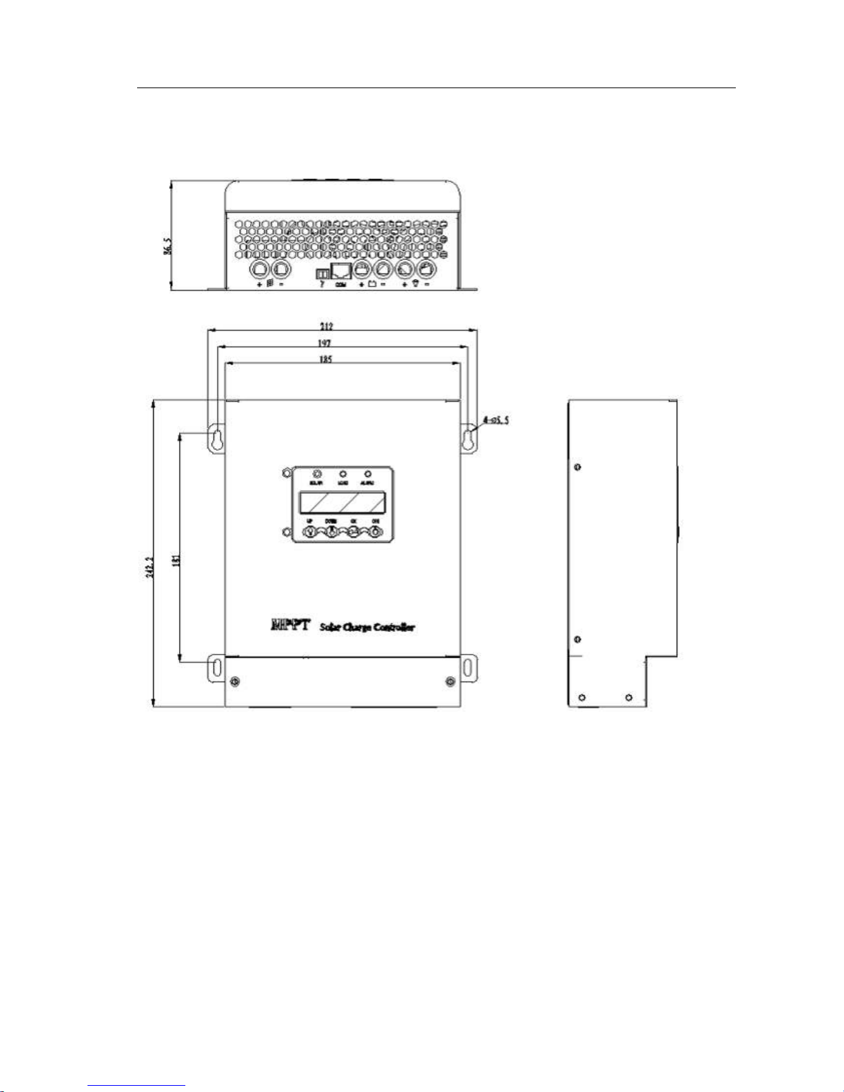
2.2.1 Outline Structure
Figure I RM-60-36/48/RM-50-36/48/RM-40-36/48 Structure Dimension (242.2×212×86.5mm)

User Manual of the RM 36V/48V Series of Solar Charge Controller
- 6 -
Figure 2 RM-30-36/48/RM-20-36/48/RM-10-36/48 Structure Dimension ( 224×178×86mm)
Notes: The outline dimension is made according to the non-standard customization, while the installation
dimension of the wall mounting type is shown in the above Figure (unit: mm) and the screw dimension is
M4.

User Manual of the RM 36V/48V Series of Solar Charge Controller
- 7 -
2.2.2 Wiring and Running
2.2.2.1 Notes for Wiring
1. Before wiring, please confiRM- that the backup battery is in the disconnection state, i.e.
the power supply is disconnected.
2. Before wiring, please carefully check the wiring bank polarity marking (pole sharing
for this equipment).
3. When the photovoltaic connection is carried out, the positive and negative poles of the
photovoltaic input should be confiRM-ed. It is not allowed to reversely connect them.
4. The negative poles of the backup battery and photovoltaic module are not allowed to be
earthed.
5. Before wiring, please confiRM- whether the backup battery voltage is consistent with
that of this equipment.
6. Before wiring, please confiRM- whether the photovoltaic input voltage is consistent with
that of this equipment.
7. The insulated cable with copper core is selected for the connecting wire (with the
maximum wire diameter of 10 mm2) and the cable is selected according to the carrying
capacity of 5A/ mm2. When wiring, please ensure that the teRM-inal is well contacted to
prevent overheat when there is high current.
8. The earth teRM-inal must be reliably earthed.
2.2.2.2Diagram of the Amphenol Connector
RJ45 signal definition(standard configuration RS48-5,LAN optional)

User Manual of the RM 36V/48V Series of Solar Charge Controller
- 8 -
2.2.2.3 Use Operation Steps
1. Confirm- that all wirings are correct and wiring polarity is correct.
2. Connect the breaker of the solar cell and battery,the lights will light up.
3. The LCD display and parameter setting are correct.
4. Various parameters of this machine have been set up when it left the factory. If there is no
special requirement, the default factory value will be taken after the machine is started up.
The customers can set up the relevant parameters by themselves if they have requirements.
5. If the machine should be shut down, please first disconnect the photovoltaic input breaker
and then those of the backup battery and electrical equipment to shut it down.
2.2.3 Instruction about the Human-computer Interface of the LCD Display Panel
Instruction
Logo
Indicator
light
color
NoRM-
al state
AbnoRM-al
state
Cause of abnoRM-ity
PV indicator
light
Green
Light
up
Flash or go
out
It will light up when the operation goes well, it will go out when
there is PV undervoltage and it will flash when there is PV
overvoltage.
LOAD
indicator
light
Green
Light
up
Flash
It will light up when the load is noRM-al, while it will flash when
there is overcurrent, the battery has low voltage and the load has
short circuit.
Fault
indicator
light
Red
OFF
Flash or
light up
It will go out when the operation goes well, it will light up when
the module has fault, the battery has short circuit, the load has
short circuit and there is overtemperature protection and it will
flash when there is PV overvoltage.
PV Indicator Light
Load Indicator Light
AlaRM- Indicator
Light
Main LCD Display
Screen
Up Page Up Key
Down Page Down
Key
OK OK Key
Battery On Key

User Manual of the RM 36V/48V Series of Solar Charge Controller
- 9 -
Operating instructions of the key functions of the front panel:
a. UP——Page Up Key: turn up the menu and the value increases when the parameter is set up;
b. OK——OK Key: enter the menu and return to the last menu;
Click—>OK (save the data);
c. Down——Page Down Key: turn down the menu and the value decreases when the parameter is set up.
d. Clear history: press OK at the same time in the history interface more than 3 s
e. Clear Power generation: press the OK at the same time more than 3 s
The display instructions of the main display screen:

User Manual of the RM 36V/48V Series of Solar Charge Controller
- 10 -
Menu Hierarchy
NO. First Menu
Second Menu
Remarks
1
Model Software version
2
Measure
Vout
Out Voltage
Ibat
Battery Current
Vpv
PV Voltage
I
Load
Load Current
Btemp
Battery temperature
Power TG
Total generation
DG
Day generation
3
Charge Status
Float
Equal
4
Setting
(default:8888)
Password check
Need professional
guidance
Float Voltage
Equal Voltage
Battery Capacity
Temp compensate
Charge Radio
Password Change
Address
Load OFF Voltage
Mppt Status
Battery Type
Factory Default
Source IP
Destination IP
Mask IP
Source Port
Destination IP
5
AlaRM- info
PV status
Bat Status
Temp Status
Load Status
6
History Record
Show the history alaRM-
records
7
Time&Data Dispaly
Setting Data&Time

User Manual of the RM 36V/48V Series of Solar Charge Controller
- 11 -
Chapter 3 Maintenance Instruction
3.1 Common Faults and Troubleshooting Process
3.1.1 Preventive Periodic Maintenance
In order to enhance the reliability of the operation of the solar charge controller, please complte
the following preventive maintenance operations:
1.Keep the environmental health to avoid dust or water drop to the controller.
2.Check whether the input and output amphenol connectors are well contacted once every
severy months.
3.Check the operating environment of the equipment and the controller should be used in the
clean and ventilated place.
4. When several power supplies are used together, the front space of the power supply rack
should be possibly expanded and the equipmetn such as air-conditioner or fan etc. should
be installed if possible.
5. The running records should be made for the daily running.
6.Periodically check the historic records of the controller.
3.1.2 Fault Maintenance Steps
1.Check the historic fault records in LCD.
2. Check whether the relevant parameter setting is incorrect or unreasonable.
3.Check wether the photovoltaic input voltage falls into the specified range.
4.Check whether there is error between the actual battery voltage and displayed voltage.
5.Check whether the charging loop is noRM-al.
6.Reset the system to check whether it can recover to the noRM-al status.
3.1.3 Maintenance Operation Steps
1. First disconnect the photovoltaic input breaker and then the battery input breaker.
2. Disassemble the wiring such as the ground wire of the photovoltaic input, backup battery,
rack connection and so on using the tools such as screwdriver etc., mark the positve and
negative poles and wrap up the connectors of the connecting wires using the insulated tape
(or heat-shrinkable tubing, fiber tubing etc.) to prevent the short circuit with other leads.
3. Loosen the fixing screws of the case cover of the controller and then maintain or replace
the machine.
4. After the machine is maintained or the new controller is replaced, lock the case cover of
the controller using the screws, connect the wiring of the ground wires of the photovoltaic
input, backup battery and rack connection etc. then conduct the power-on operation
according to the use operation steps in 2.2.2.3.
User Manual of the RM 36V/48V Series of Solar Charge Controller
- 12 -
3.1.4 Maintenance of the Solar Cell Plate
The solar photovoltaic plate is an integral part of the solar photovoltaic power generation
system and is related to the photovoltaic use efficiency of the whole system, thus the
installation soundness of the photovoltaic plate and cleanness of the cell plate surface must be
guaranteed.
1. Ensure to first disconnect the photovoltaic polar plate, then the output and backup battery
and the order should be not reverse.
2. Often check whether the installation of the photovoltaic polar plate is solid.
3. Carry out the electric leakage check for the wire connectors to avoid the electric leakage
on the rainy and snowy day.
4. Periodically clean and maintain the polar plate surface.
3.1.5 Other Maintenance
The handling measures after the faults occur:
1. For the general faults of the equipment, please carefully read this manual. On the premises
of having sufficient confidence, make judgment and troubleshooting according to the
manual.
2. In case of the faults which cannot be removed, the maintenance must be carried out by the
professional technician or directly contact us.
3.1.6 Diagnosis of the Common AbnoRM-ities
If the controller cannot noRM-ally work after you start it up or the abnoRM-ity occurs after it
works for a while, you can find out the possible causes by referring to Table 3-1. Meanwhile,
please note to check whether it is caused by the external environment, such as the temperature
or humity does not meet the requirement. If it cannot still work noRM-ally after handling
according to the methods in Table 3-1, please hand it over to the professional personnel for
maintenance. This section only includes some simple fault diagnosis procedure. If the
diagnosis result is unclear, or the obtained infoRM-ation is insufficient for the problem solving,
please contact the local office or distributor of our company for handling.
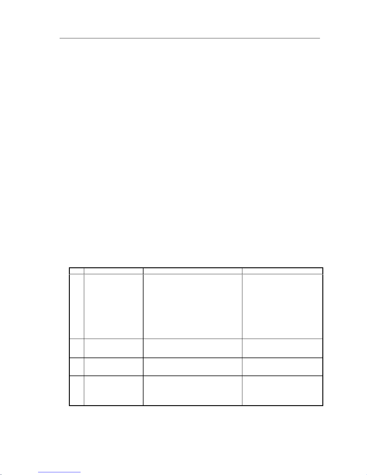
Table 3-1 Reference Table for Fault Diagnosis
No.
Phenomenon
Cause
Handling Method
1
After the PV input switch
is switched on, the LCD
has no display.
a. The PV power supply loop is
disconnected.
b. The PV power supply voltage does not
match the battery voltage of this
equipment.
c. The voltage polarity of the PV power
supply is reversely connected.
d. The plug is loosened due to transportation
vibration.
e. LCD is damaged due to extrusion or
impact.
a. Connect the PV power supply
loop
b. Adjust the PV power supply
voltage to the noRM-al value
c. Correctly connect the PV power
supply
d. Disassemble the machine case
and plug again
e. Send it to the local office for
maintenance
2
Immediate undervoltage
awaRM- or protection
after powering on.
a. The backup battery voltage is too low.
b. Whether the DC loop wiring is loosened.
a. Adjust the backup battery voltage.
b.Check whether the wiring is solid.
3
Immediate overvoltage
awaRM- or protection
after powering on.
a. The backup battery voltagedoes not match
the battery voltage of this equipment.
Adjust the backup battery voltage to
the noRM-al value
4
After the
Battery is
connected, LCD
has no display.
a. Do not press the key “BAT-ON(ON)” of
LCD;
b. The battery voltage does not fall into the
noRM-al range;
a.Press the key “BAT-ON(ON)” of
LCD to start up the auxiliary
powre supply;
b. Adjust the battery voltage to the
noRM-al value

User Manual of the RM 36V/48V Series of Solar Charge Controller
- 13 -
Chapter 4 Transportation and Storage
4.1 Transportation
During handling, please handle with care. The warning signs on the packing box should be
strictly followed. When being transported, it should be placed in strict accordance with the
direction indicated on the packing box to avoid the device damage due to vibration. For the
long-distance transport, it is not allowed to be packed in the open vehicles or ship. It should be
not packed with the inflammable and explosive articles. When it is transshipped on the way, it
should be not stored in the open air. During transportation, it should be kept away from rain,
snow or other liquid substance, long-teRM- basking of sunshine and mechanical damage and so
on.
4.2 Storage
When the equipment is stored, the placement direction should strictly follow the direction
indicated on the packing box. The packing box should be cushioned with 20cm away from the
ground and at least 50cm away from the wall, heat source, cold source, window or air inlet.
The environment temperature of storage is -40~70℃ and the relative humidity is ≤93%.
There should be no various haRM-ful gases, inflammable or explosive articles and corrosive
chemicals in the warehouse and there should be no strenuous mechanical vibration, impact and
strong action of a magnetic field. The storage period is generally 6 months under the conditions
specified in this article if there are no other regulations. When it exceeds 6 months, the
inspection should be carried out again.
 Loading...