

Page 1
Manual and Configuration
KNX Smartmeter 85A (RT)
Advice
The contents of this document may not be wholly or partially, reproduced, transferred, distributed or stored in any form
without prior written approval by Enertex® Bayern GmbH.
Enertex® is a registered trademark of Enertex ® Bayern GmbH. Other product- and company names mentioned herein
can be names of trademark or registered trademarks of their respective owners.
This manual may be changed without notifications or notice and makes no claim to completeness or accuracy.
Enertex® Bayern GmbH – Ebermannstädter Straße 8 - 91301 Forchheim - Deutschland - mail@enertex.de
Page 2

Handbuch-KnxSmartmeter-85A-en-3.odt, 2018-10-04 Seite 2 von 69
Contents
Notes.............................................................................................................................................................. 3
Function........................................................................................................................................................ 4
Technical specifications.............................................................................................................................. 4
Assembly....................................................................................................................................................... 7
Connection diagram................................................................................................................................. 7
Assembly of the current sensors.............................................................................................................. 8
Commissioning............................................................................................................................................ 9
ETS-Application..........................................................................................................................................10
Specification........................................................................................................................................... 10
Data base file......................................................................................................................................... 10
Examples of settings.............................................................................................................................. 10
Example 1:
Visualization of
energy consumption...............................................................................................................................................10
Example 2:
Bidirectional Counter for Photovoltaics..................................................................................................................16
Measurement quantities......................................................................................................................... 23
General Function Concepts................................................................................................................... 25
Cyclical transmitting...............................................................................................................................................25
Transmit at Change................................................................................................................................................25
Bidirectional Counter..............................................................................................................................................26
Intermediate Counter..............................................................................................................................................27
Tariff Costs Counter...............................................................................................................................................27
Preset of a Counter................................................................................................................................................28
Message of limit values..........................................................................................................................................28
Recording on the SD card......................................................................................................................................29
Adjusting the real-time
clock without bus access.......................................................................................................................................31
Parameter............................................................................................................................................... 31
General...................................................................................................................................................................31
Measurement..........................................................................................................................................................33
Energy counter / Tariff cost counter.......................................................................................................................41
Tariff........................................................................................................................................................................48
Group Objects........................................................................................................................................ 51
Firmware update......................................................................................................................................... 69
Revision history......................................................................................................................................... 70
Enertex® Bayern GmbH – Ebermannstädter Straße 8 - 91301 Forchheim - Deutschland - mail@enertex.de
Page 3

Notes
Handbuch-KnxSmartmeter-85A-en-3.odt, 2018-10-04 Seite 3 von 69
• Installation and assembly of electrical equipment must be carried out by qualified
electricians.
• When connecting KNX/EIB interfaces specialist skills are required.
• Ignoring the instructions can damage the device, as well a fire or other hazards can
arise.
• These instructions are part of the product and must be left with the end user.
• The manufacturer is not liable for costs or damages incurred by the user or third parties
through the use of the device, misuse or malfunction of the connection, malfunction of
the device or user equipment.
• Opening the housing, other unauthorized alterations and or modifications to the device
will invalidate the warranty!
• Only the current sensors, which are included, may be connected to the current sensor
inputs.
• The manufacturer is not liable for improper use.
Enertex® Bayern GmbH – Ebermannstädter Straße 8 - 91301 Forchheim - Deutschland - mail@enertex.de
Page 4

Function
Handbuch-KnxSmartmeter-85A-en-3.odt, 2018-10-04 Seite 4 von 69
The KNX Smartmeter is a bidirectional counter for measuring the active and reactive power or
energy, as well for power quality monitoring. The measurement will be done in three-phase
system or in three separate single-phase systems with the accuracy of class 1 (1%)
In the accuracy class 1 according to EN 62053-31 only accuracy requirements for the
measurement range between 2% and 100% of rated current are determined. For smaller
currents no requirements are defined, as these can not be accurately detected with conventional
current transformers. In contrast, the Enertex KNX Smartmeter uses high precision (Rogowski-)
current sensors which are calibrated to the device in factory. Thus, very small currents to
0.002% (2mA) of rated current are accurately measurable. In addition, the current is measured
with very little loss (< 2mW loss). The provided current sensors are suitable for through-hole
mounting and can be installed directly at the main supply point of the grid.
The Smartmeter is powered exclusively via the bus. Therefore, the device can even be operated
if there is no voltage at the voltage inputs or the voltage has been separated.
The measurement range of the active power extends from 0.5W to 19.550W or 58.650W (threephase). Energy values or measurement values for monitoring the power quality can be recorded
for analysis on a SD card.
All measured values (current, voltage, active power, reactive power, active energy, reactive
energy, power factor, THD-U, THD-I, power harmonics, unbalanced load, zero current, power
frequency) are shown on the KNX bus.
Besides specialized functions for performance-based load control, optimization of the inherent
energy demand with PV facilities, calculating the usage or feeding charge with tariff switching
the ETS application also provides various monitoring functions. In case of exceed of limits these
functions report events as power outages, high voltage spikes, high power distortion, high
reactive energy, highly non-uniform loading of the three phases (unbalanced load) or high
neutral loading on the bus. To assess the power quality harmonics up to the 50th harmonic of
current and voltage are measured. The numerous monitoring features enable fast accurate
analysis of network-related failures, malfunctions and damages of electrical equipment.
The device variant with the RT option can also be operated without a KNX bus. To do this, a
24VDC power supply must be connected to the KNX terminal. In this mode, all measurement
data of the recording mode "All measured values without mains harmonics" are recorded on the
SD card every minute as described in the section "Recording on the SD card". The recording
times for the measured values are selected in this mode according to an internal batterybuffered clock, which is factory set to the local time of Berlin (UTC / GMT +1 hour) and deviates
from the real time by a maximum of one minute per year. If necessary, the clock can be adjusted
using the SD card. The adjustment of the clock without KNX bus is described in section
"Adjusting the real-time clock without bus access".
Note: The security against tampering of the current counter, required for billing purposes, can
not be guaranteed with this Smartmeter. Therefore this KNX device is not a current counter for
billing purposes in terms of the standard (for example IEC 62052-11).
Technical specifications
KNX Voltage:
DC 21 ... 32 V SELV
Current consumption:
Typical power consumption:
Enertex® Bayern GmbH – Ebermannstädter Straße 8 - 91301 Forchheim - Deutschland - mail@enertex.de
< 18mA
0.28W
Page 5

Handbuch-KnxSmartmeter-85A-en-3.odt, 2018-10-04 Seite 5 von 69
Connections Voltage measurement input:
Cross section:
Input voltage:
Power frequency:
Current sensor input:
Cross section:
Ground terminal:
Cross section:
Max. cross section through
current sensor:
EIB / KNX Connection:
Installation Scope of application:
Protection type:
Ambient temperature:
Protection class:
Over voltage category
for voltage input:
4 pol. screw terminal
0,33 ... 4 mm² / AWG 22 ... 12
max. 460Vrms
50Hz
3 x 3 pol. screw terminal
0.2 ... 4 mm² / AWG 24 ... 12
3 pol. screw terminal for functional earth,
internal bridged
0.2 ... 4 mm² / AWG 24 ... 12
25 mm² / AWG3
Connector Type 5.1
For use indoors
IP20
-5 °C ... 45°C
II
400Vrms / CAT IV
Housing Type:
Width:
Dimensions:
Flammability:
General Certification:
Applicable standards for
CE-marking:
Supplied
Current sensors:
accessories
SD-card
Measurement
values
Current, Voltage, Active power, Reactive power, Active energy, Reactive
energy, Power factor, THD-U, THD-I, Unbalanced load, Zero current, Power
frequency, Power harmonics up to the 50th harmonics
DIN rail housing for 35 mm rail
4 Units
70,0 x 89,6 x 62,9 mm (L x W x H)
UL94-V0
EIB/KNX certificated
Tested for safety in accordance with DIN EN
61010-1
Tested for EMC compliance in accordance with
DIN EN 50491-5
Meets requirements for housholds according to
DIN EN 50491-5-2 and for industrial according
to DIN EN 50491-5-3
3 x current sensor (Rogowski-converter) with
each 1,5m Measurement line and centering clip
Micro SD card with adapter
Accuracy
class
Active energy according to
DIN EN 62053-21:
Starting current:
Max. current (Imax):
Enertex® Bayern GmbH – Ebermannstädter Straße 8 - 91301 Forchheim - Deutschland - mail@enertex.de
1 (1%)
2mA (rms value)
85A (rms value)
Page 6

Handbuch-KnxSmartmeter-85A-en-3.odt, 2018-10-04 Seite 6 von 69
Measurementaccuracy
Active power:
Measurement ranges
0,5W ... 2W:
2W ... 20W:
20W ... 20kW:
Current:
Measurement ranges
1mA ... 10mA:
10mA ... 100mA:
100mA ... 85A:
Voltage:
Measurement range
30V ... 460V:
Frequency:
Measurement range
Typical measurement deviations per channel
< 10% or 0.1W
< 5%
< 1%
Typical measurement deviations
< 5% or 0.5mA
< 2%
< 1%
Typical measurement deviation
< 0.5%
Typical measurement deviation
40Hz ... 60Hz:
THD-I, Harmonics I:
Measurement ranges
0% ... 10%:
10% ... 100%:
THD-U, Harmonics U:
Measurement ranges
0% ... 10%:
10% ... 100%:
< 0.1%
Typical measurement deviations
(at 5Arms rating current)
< 0.2% absolute
< 1% absolute
Typical measurement deviations
(at230Vrms rating voltage)
< 0.2% absolute
< 1% absolute
Enertex® Bayern GmbH – Ebermannstädter Straße 8 - 91301 Forchheim - Deutschland - mail@enertex.de
Page 7
Assembly
KNX
-
+
N V1 V2 V3
Voltage Inputs
Current Inputs
I1 I2 I3
Connection diagram
Handbuch-KnxSmartmeter-85A-en-3.odt, 2018-10-04 Seite 7 von 69
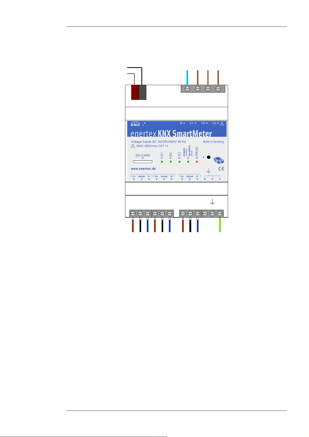
Figure 1: Terminal connection diagram
ATTENTION DANGER!
Electrical shock on contact with live parts. Electrical shock can result in death.
Disconnect the mains before working on device and cover up live parts in the
vicinity!
The neutral conductor and the measurement inputs for the 3 voltage measurement channels V1,
V2 and V3 are connected to the overlying screw terminal. When measuring a three-phase
system the phases L1, L2 and L3 have to be connected to V1, V2 and V3. If the Smartmeter is
not in three-phase operation then the phase voltage of the corresponding current channel has to
be connected to voltage measurement channel V1, V2 and V3. For example, if three powers are
to measure at one single phase, then this phase has to be connected to all three channels V1,
V2 and V3. The supply for the voltage inputs may be made from any location downstream the
main fuse, since the voltage inputs are designed for over voltage category IV. Insulation and
electro-magnetic imunity is designed for overvoltage category 4. So, the voltage inputs need not
to be additionally fused.
The EIB/KNX bus is connected on the upper left, grey / red terminal. The Smartmeter is powered
solely by the KNX bus.
Optionally a ground can be connected to one of the three ground terminals. By a connected
grounding the measurement accuracy for very small currents and powers is increased. Thus,
when measuring the current, the measurement deviation is reduced by about 0.3mA or when
measuring the power the deviation is reduced by about 70mW. By connecting the grounding the
KNX bus is connected via a capacitance of 15nF to ground.
Enertex® Bayern GmbH – Ebermannstädter Straße 8 - 91301 Forchheim - Deutschland - mail@enertex.de
Page 8
The current sensors have to be connected to the lower terminals of the Smartmeter with the
10mm
4
6
m
m
3
9
.
7
m
m
1
P+
following assignment:
• I+ : brown
• I- : white
• Shield : black (drain wire)
Assembly of the current sensors
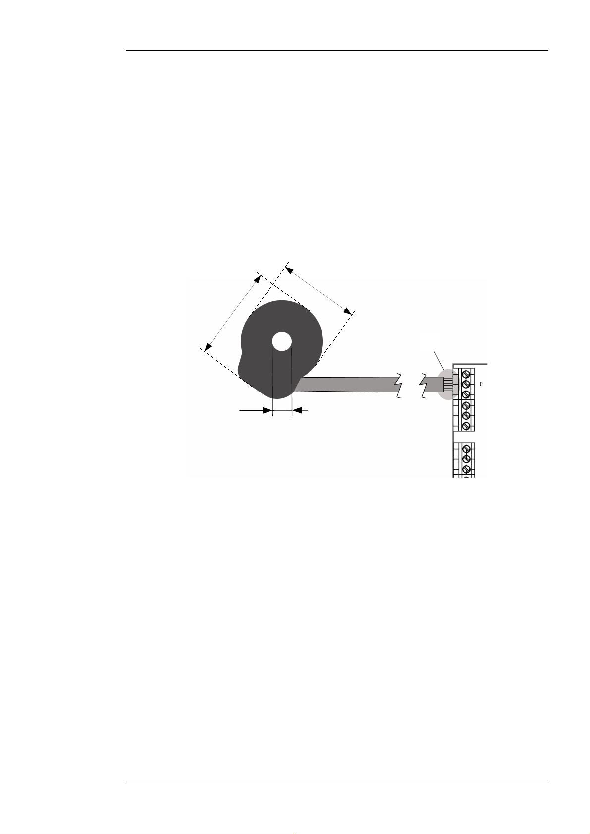
The current-carrying conductor, to be measured, must be passed through the current sensor. If
possible, the line should be passed vertically through the current sensor. Thus, the highest
precision is achieved in the current measurement. In order to fix the current sensor, it could be
fixed with a cable strap at the conductor. It is recommended for safety reasons to lead the
conductor with insulation through the current sensor.
Handbuch-KnxSmartmeter-85A-en-3.odt, 2018-10-04 Seite 8 von 69
Figure 2: Dimensions of the 85A current sensor in mm
Safety note: In the vicinity of label 1 of Figure 2 the current sensors cable is only single
insulated. At this point a savety distance of at least 5mm has to be adhered to all non insulated
live conductors. Similarly a safety distance of at least 10mm from the screw terminals has to be
adhered to all non insulated live conductors. However, the sheath of the line for the current
sensors has a reinforced insulation. Hereby no safety distances to the vicinity are required.
Since the current sensors are calibrated for each current channel it must be ensured that the
accompanying current sensors are connected to the corresponding channel. For this purpose a
corresponding marking of the channel is mounted on each current sensor. In addition, the
current sensors should be connected only to that Smartmeter, with which they were delivered.
To avoid any confusion, the serial number of the Smartmeter is attached to the line of a current
sensor. The serial number can also be recovered lateral of each Smartmeter.
A power count arrow (for positive power count direction) is attached by
on the current
sensors. A power flow in this direction corresponds to a positive power value. Usually, the
current sensors are mounted so that the power count arrow shows from the energy source to
the energy consumers, so that an energy consumption has a positive impact for the balance
energy counter.
The lines to the current sensors should be laid according to EMC requirements. This is
especially important when a high accuracy for currents below 100mA (equivalent to 25W) is
required. Therefore the following recommendations are made:
• The line should be laid in a minimum distance of 2cm to power lines.
Enertex® Bayern GmbH – Ebermannstädter Straße 8 - 91301 Forchheim - Deutschland - mail@enertex.de
Page 9

Handbuch-KnxSmartmeter-85A-en-3.odt, 2018-10-04 Seite 9 von 69
• The line should be laid at a distance of at least 10cm to high-frequency sources of
interference. These include for example:
◦ Inverter, converter
◦ WLAN Router
◦ Counter with GSM interface
◦ Equipment of a radio - bus, as Enocean, KNX-RF ...
For the highest precision the lines to the current sensors can also be cut to the minimum
required length. When shortening it is to make sure that also the drain wire is connected to the
shield terminal. In addition, care must be taken that after shortening, the cable shield is again
insulated by a shrinking tube, as it was the case in the original condition. As an alternative to this
insulation the electrical safety can also be ensured by maintaining a safety distance between the
non - insulated part of the shield and all the live conductors by at least 10mm.
If necessary, it is also possible to extend the lines for the current sensors up to 10m. However,
an increasing cable length is accompanied by a higher disturbance in the measurement signal.
Thus, the measurement accuracy for small currents is reduced. It is therefore recommended not
to extend the line, if currents below 500mA (about 100W) shall be accurately measured. To
affect the measurement accuracy as little as possible in a case of an extension the following is
recommended:
◦ Only use shielded lines with at least 0.5mm² . The shield of the extension must be
connected to the shield wire (drain wire) of the existing measurement line.
For safety reasons the extension has to be attached so that from the shield and the wires of the
extension to all live parts in the vicinity of the extension a double or reinforced insulation is
maintained. This can be achieved by insulation and/or the observance of minimum distances.
Commissioning
After connecting all the cables according to the connection diagram 1 the device is ready for
operation. Once the KNX bus is connected, the “POWER” LED lights up permanently green after
a short start-up (about 3 seconds). From that time the device performs measurements
continuously.
By a short light up the channel LEDs E1, E2 and E3 signalize measuring an energy amount of
1/1000 kWh in the particular channel. When the Smartmeter record data onto the SD card, the
POWER LED lights up red during the writing process. To prevent data loss on the SD card the
SD card may not be drawn during this writing phase. SD card is inserted in a way, that the
contacts of the SD card are on the top.
◦ The extension should be soldered to the existing measurement line.
◦ The shield of the extension or the extension drain wire must be connected to the
Smartmeter at the shield terminal.
Enertex® Bayern GmbH – Ebermannstädter Straße 8 - 91301 Forchheim - Deutschland - mail@enertex.de
Page 10
ETS-Application
Specification
ETS: from Version 3.0d, Patch A
Data base file
In http://www.enertex.de see the current ETS database file and the current product description.
Examples of settings
Below examples are presented, which show how the KNX Smartmeter can be used. To this end
appropriate adjustments in the ETS will be shown. The adjustments can be adopted directly.
Example 1:
Visualization of
energy consumption
Handbuch-KnxSmartmeter-85A-en-3.odt, 2018-10-04 Seite 10 von 69
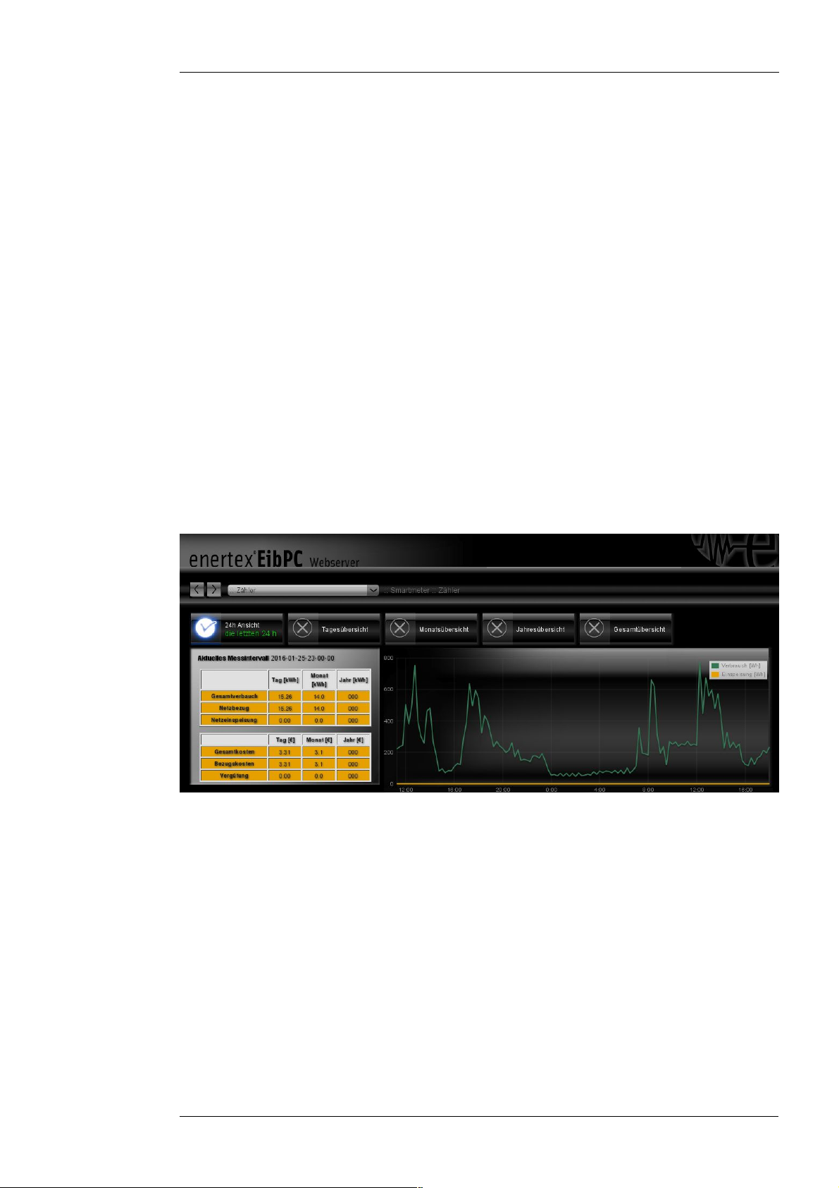
In the first example the progress of energy consumption and the progress of the energy costs of
a residential house shall be recorded and shown on the bus. The consumption values
transmitted on the bus can be visualized for example on the web server of Enertex EibPC over
the last 30 hours.
Figure 3: Example of the visualization of energy consumption
Furthermore it is shown in this example, how the progress of the three-phase active power can
be displayed completely on the bus and the Smartmeter is configured such, that it also records
all measurement values on the SD card every 15 minutes.
In this example the following topics are treated: Installation of the Smartmeter, tariff counter,
intermediate counter, preempting a count, SD card, transmitting in case of change and time.
In this example the installation of the Smartmeter is a three-phase at the house connection.
Generally the current sensors are installed directly downstream the current counter of the
energy supplier. Similarly the voltage may be tapped directly downstream the current counter.
Enertex® Bayern GmbH – Ebermannstädter Straße 8 - 91301 Forchheim - Deutschland - mail@enertex.de
Page 11
Handbuch-KnxSmartmeter-85A-en-3.odt, 2018-10-04 Seite 11 von 69
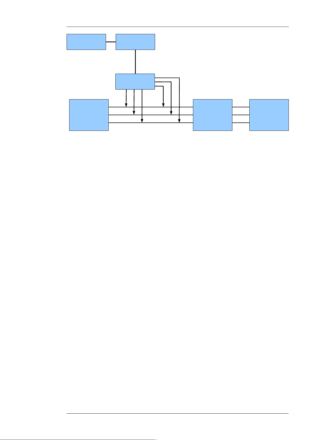
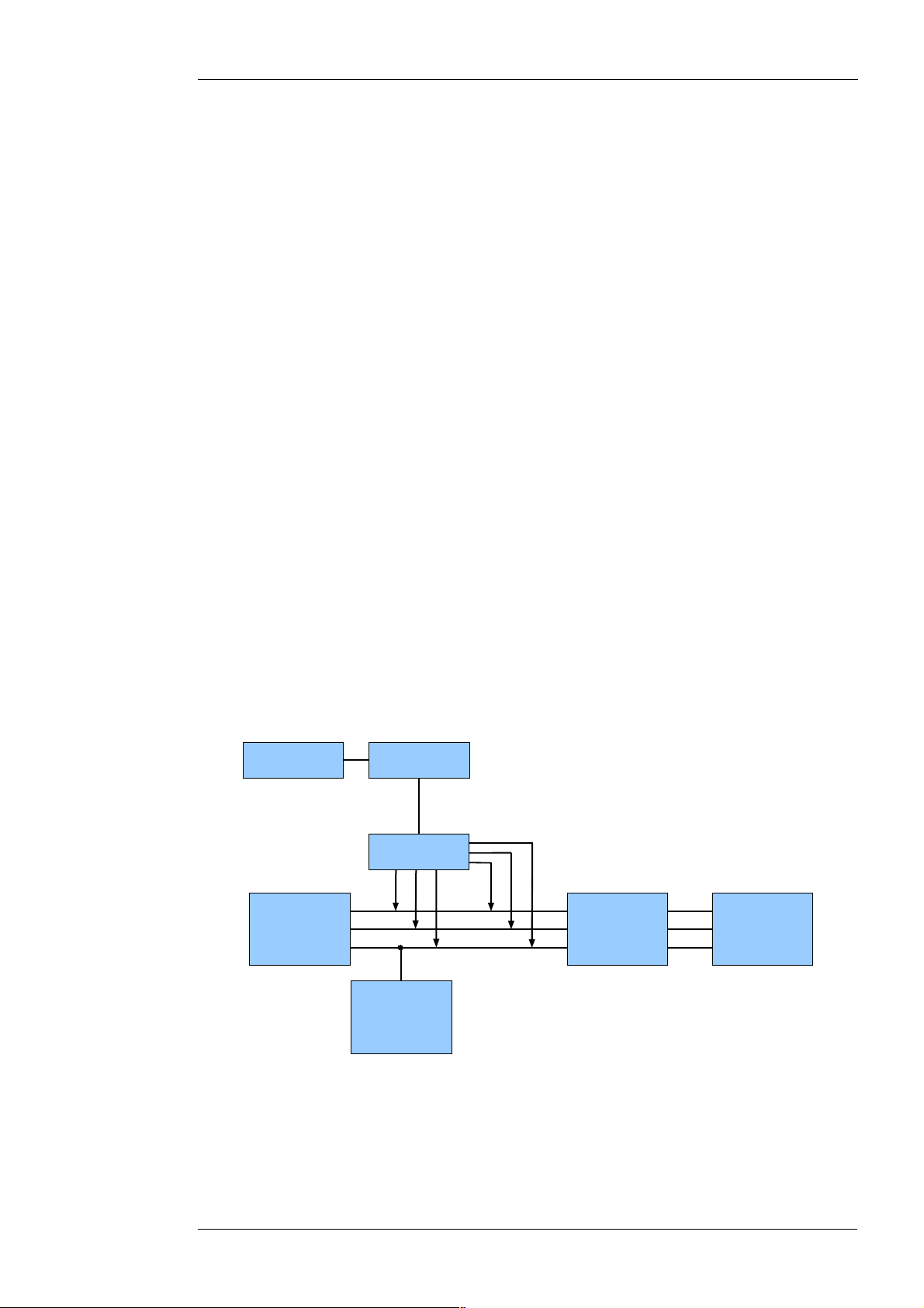
KNX-BUSVisualization
Current
Voltage
Mains
power supply
Consumer
Smartmeter
Current Counter
(from Supplier)
Figure 4: Connection of Smartmeter to record the total energy consumption of a residential
building
When connecting make sure that the current sensors are oriented such, that the applied power
arrows show from the public supply network in direction of consumers within the home. Next,
make sure that voltage L1 is connected to V1, voltage L2 to V2 and voltage L3 to V3. Likewise,
the current sensor at conductor L1 has to be connected to I1, the current sensor at conductor L2
to I2 and the current sensor at L3 to I3..
Attention: If a channel is reversed, the measured values for the active power and active
energies are distorted strongly.
After connecting the lines according to the connection plan the device is ready for operation.
Once the KNX-bus is connected, the “POWER” LED lights up permanently after a short start-up
procedure (about 3 seconds). From that time the device performs measurements permanently. If
not already done the SD card for recording the measurement data has to be inserted.
Below is shown, which relevant parameter related to this example has to be set in the ETS.
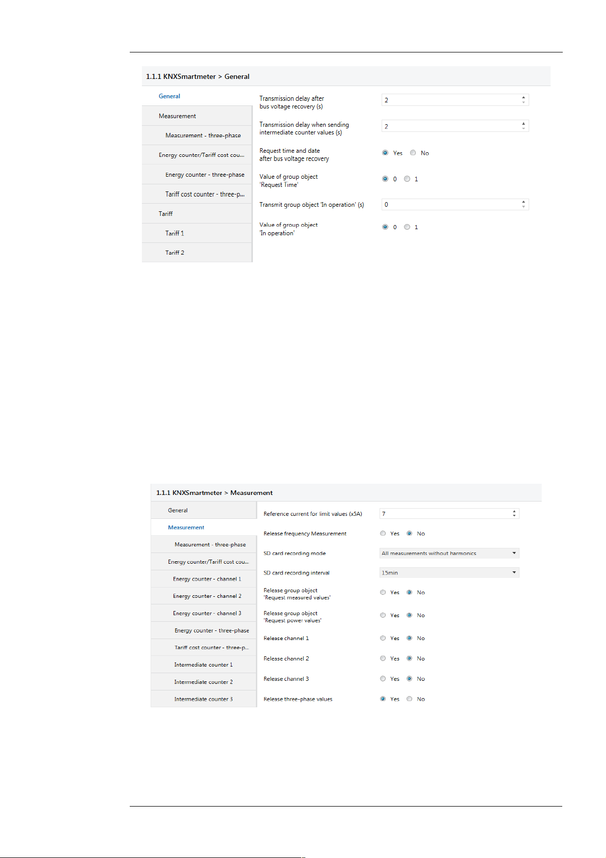
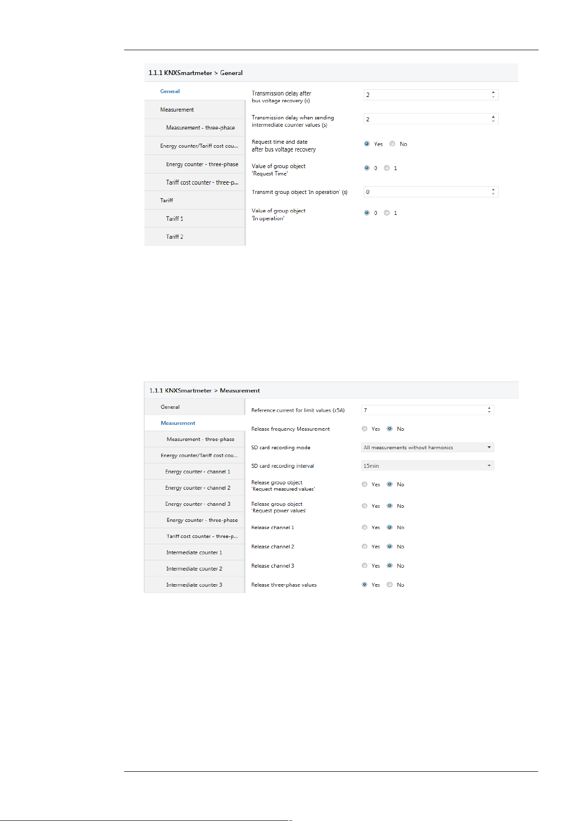
In the tab “General” the parameter “Request time and date after bus voltage recovery” should be
set. Otherwise the default values can be adopted. By setting the parameter the Smartmeter
requests once after each restart of the application the current time and date from the bus. This
data must be provided from an other device in via a group address. If no device exists on the
bus, which provides a time then this example can not be applied. The time is needed since the
Smartmeter transmit the measurement values always synchronized with the day time on the
bus, e.g. on the minute or hour. The time is also needed for the timely recording of the
measurement data on the SD card.
Therefore the tab “General” has to be parameterized as follows:
Enertex® Bayern GmbH – Ebermannstädter Straße 8 - 91301 Forchheim - Deutschland - mail@enertex.de
Page 12
Handbuch-KnxSmartmeter-85A-en-3.odt, 2018-10-04 Seite 12 von 69
Figure 5: Settings „General“ Example 1
The settings in the tab “Measurement” can be seen in Figure 6. It is advisable that in the
parameter “Reference current for limit values (x5A)” the security value is entered with which the
lines at the measurement point of the Smartmeter are protected. In this example the reference
value is therefore adjusted to 35A corresponding to the protection fuse of the house connection.
Therefore a parameter with the value 7 is entered in “Reference current for limit values (x5A)”.
This setting results in a viable range of values for the subsequent indication of current and power
limits.
Since only the measurement of three-phase values is relevant in this example, only these are
released in the settings. Otherwise the default values can be adopted. With the default settings
for the SD card recording, all measured values except the harmonics are recorded on the SD
card. With a parameterized recording interval of “15min” each 15 minutes a record of all
measurements (currents, voltages, powers, energy counter, THDs, frequency, power factors,
current and voltage peaks) on the SD card is done. The measurements are written in CSV
format to a file. At the beginning of each new day a new recording file is generated. Thus, the
data on the SD-card are ordered by day to a certain extent. The csv-files can directly be opened
and processed by a spreadsheet program such as Excel, Openoffice Calc or Gnumeric.
Figure 6: Settings „Measurement“ Example 1
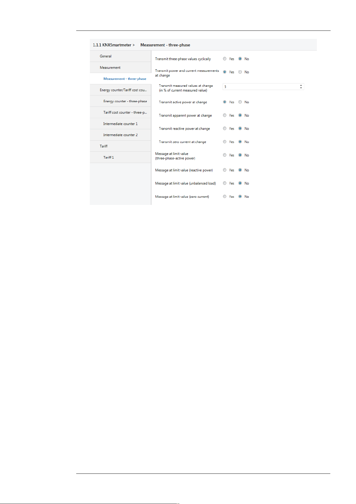
In the next tab “Measurement three-phase” can be parameterized, which three-phase values are
to be transmitted on the bus.
Enertex® Bayern GmbH – Ebermannstädter Straße 8 - 91301 Forchheim - Deutschland - mail@enertex.de
Page 13
Handbuch-KnxSmartmeter-85A-en-3.odt, 2018-10-04 Seite 13 von 69
Figure 7: Settings „Measurement three-phase“ Example 1
If, as in this example, the three-phase power shall be displayed on the bus seamlessly, the panel
“Transmit power and current measurements at change” has to be enabled. Then further buttons
are opened, with which this function can be specified. In the panel “Transmit measured values at
change” a percentage rate of 5% is indicated. Thus, a new measured value is transmitted, if the
measured value has been changed by more than 5% with respect to the value last transmitted
on the bus. With this setting the measurement on the bus can be effectively tracked without
which the bus is flooded with unnecessary messages. If the number of messages is still too high
with this settings, then the number of transmitted messages can be reduced by increasing the
percentage value. However, this goes hand in hand that the measured values can be tracked by
the bus with less accuracy. Here a appropriate compromise depending on the fluctuation of the
consumption loads should be found between the deviation of the indication from the current
measurement and the operational demands of the bus. Finally it should be configured, which
measurements are to transmit in cases of changes. Since only the active power is of interest,
only that button is activated.
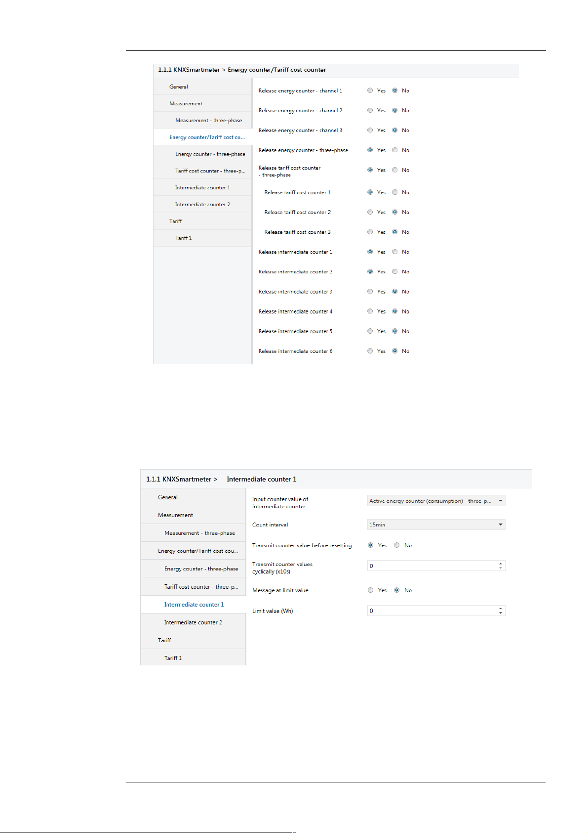
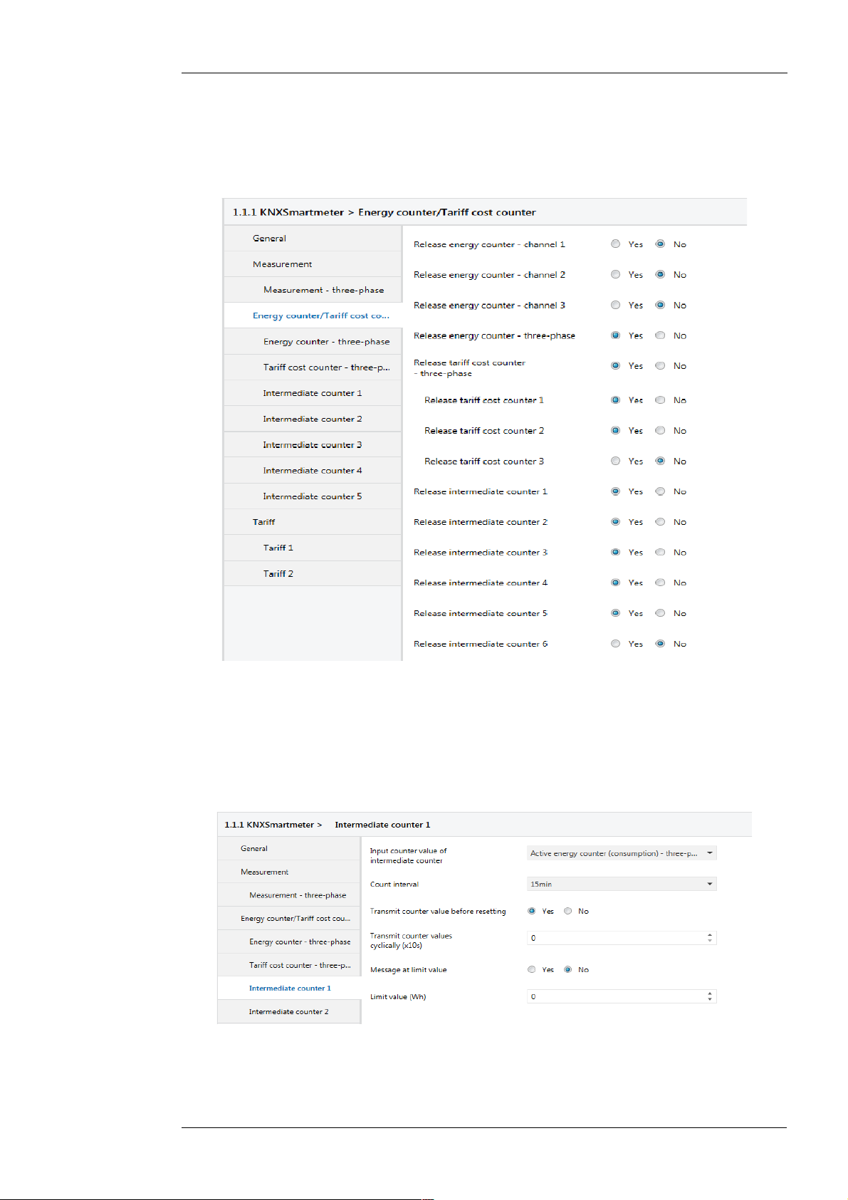
In the following tab “Energy counter/ Tariff cost counter” from Figure 8 the used counter can be
released. Since in this example only the three-phase consumption and its costs are to be
visualized, only the energy counter “Energy counter three-phase” and the cost counter “Tariff
cost counter 1” is released. Furthermore two other so-called intermediate counter are required in
this example to transmit quarter-hour-consumptions and to transmit daily consumption costs
(=daily cost of electricity). These counters are released as well:
Enertex® Bayern GmbH – Ebermannstädter Straße 8 - 91301 Forchheim - Deutschland - mail@enertex.de
Page 14
Handbuch-KnxSmartmeter-85A-en-3.odt, 2018-10-04 Seite 14 von 69
Figure 8: Settings „Energy counter/Tariff costs counter“ Example 1
In the following two tabs “Energy counter - three-phase” and “Tariff costs counter - three-phase”
no adjustments have to be done. Here the default values are taken.
Now the energy counter in the tab “Intermediate counter 1” is configured to count the quarterhour consumption. For this the “Input counter value of intermediate counter” has to be set to
“Active energy counter (consumption) - three-phase”. The counting interval is set to “15min”.
Furthermore the setting “Transmit counter value before resetting” is enabled:
Figure 9: Settings „Intermediate counter 1“ Example 1
With this configuration the intermediate counter sums up the three-phase energy consumption
each about 15 minutes and transmits this amount on the bus at the end of the interval. After that
the intermediate counter resets and adds the energy consumption again. Thereby the time
intervals are synchronized with the day time, so that the time intervals only start and end at
times XX:00 (=every hour), XX:15 and XX:45. Thus, these counters can also measure
synchronous to other current counters. Finally the 3-phase energy consumption of the last 15
minutes is transmitted cyclically after each quarter of an hour by this parametrization. Thereby
Enertex® Bayern GmbH – Ebermannstädter Straße 8 - 91301 Forchheim - Deutschland - mail@enertex.de
Page 15
Handbuch-KnxSmartmeter-85A-en-3.odt, 2018-10-04 Seite 15 von 69
the energy consumption of intermediate counter 1 is transmitted by the group object “Energy
counter-previous value” on the bus. The energy consumption is transmitted in the unit Wh.
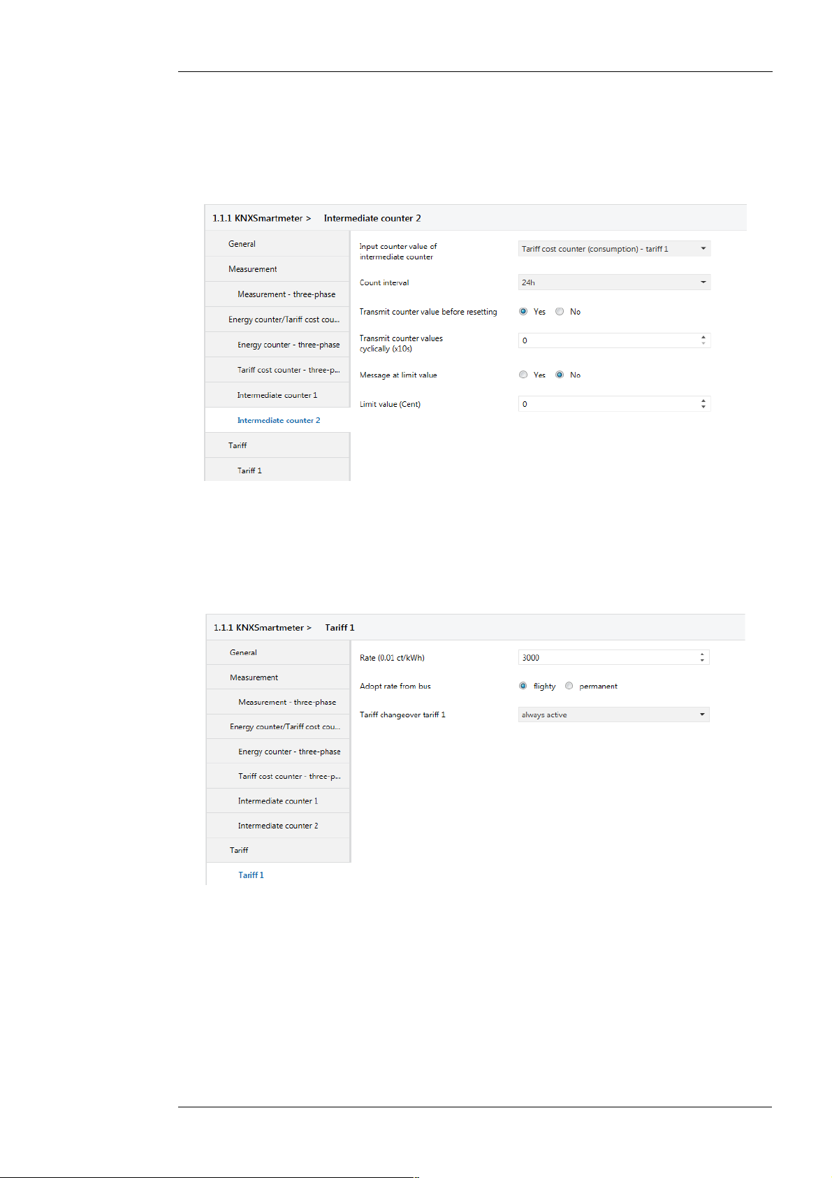
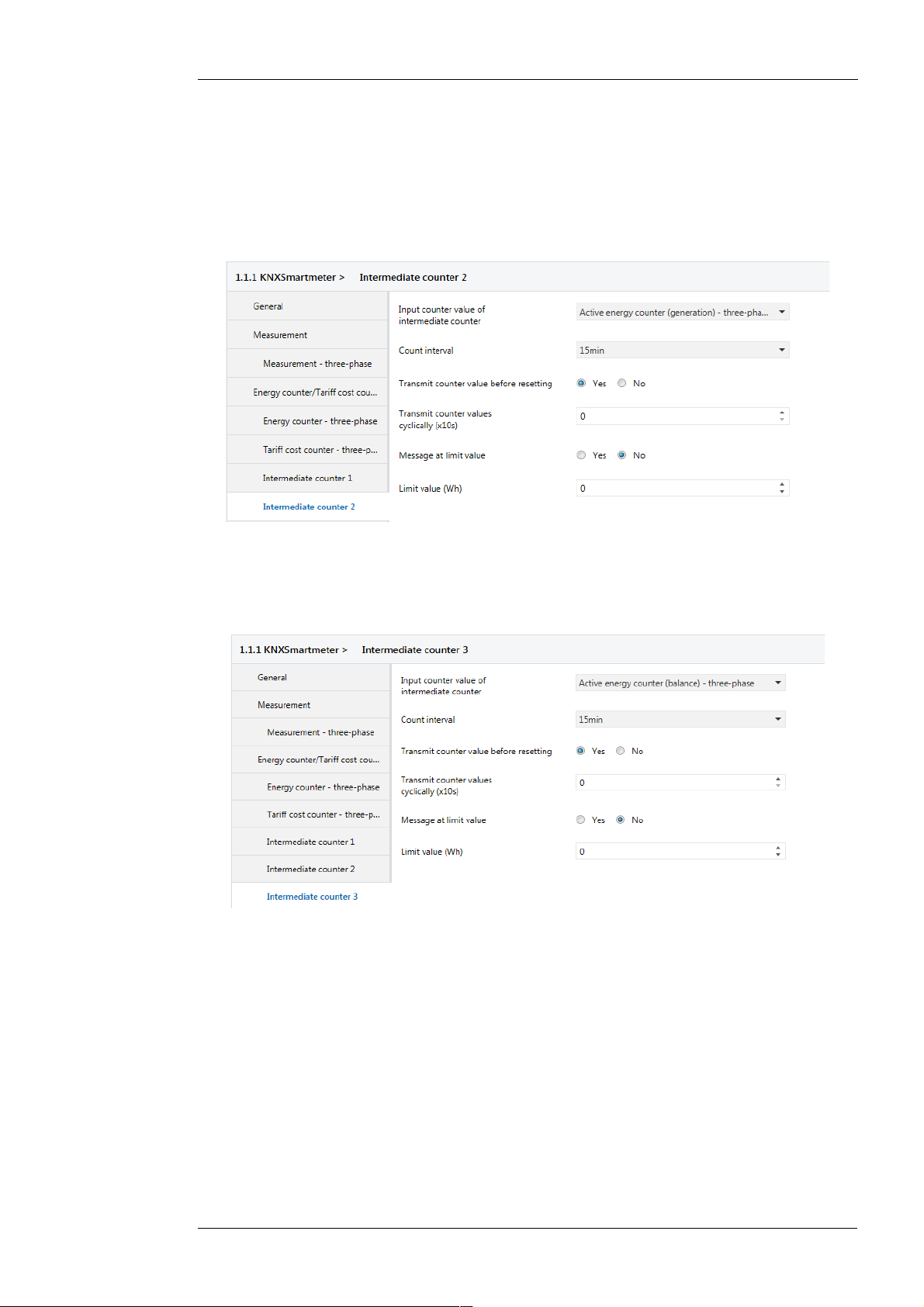
Similarly, the intermediate counter 2 is configured to transmit each daily energy costs at the end
of a day on the bus. For this purpose “Tariff cost counter (consumption) - tariff 1” is used as
input value in intermediate counter 2. The counting interval is set to “24h” Furthermore the
adjustment “Transmit counter value before resetting” is enabled again:
Figure 10: Settings „Intermediate counter 2“ Example 1
The energy costs which have been summed up over the day are then transmitted on the bus at
the end of a day via the group object “Costs counter-previous value”of intermediate counter 2.
The transmitted value represents the energy costs in cent.
Finally a tariff must still be specified to calculate the costs. Thereby “Tariff 1” is released in the
tab “Tariff”. Then the parametrization of tariff 1 is done in tab “Tariff 1”:
Figure 11: Settings „Tariff 1“ Example 1
In the panel “Rate” the electricity rate is given in 0.01 ct/kWh. This means for a given current
rate of e.g. 30ct/kWh a value of 3.000 has to be specified here. Furthermore it has to be
specified here when the tariff shall be valid. In this simple example only one electricity tariff
should be configured, which is valid around the clock. For this purpose the entry “always active”
is selected in the panel “Tariff changeover tariff 1”.
The parametrization presented in this section causes the Smartmeter to transmit the following
group objects cyclically: “Energy counter-previous value” (ID 105), “Costs counter-previous
value” (ID 115), “Active power” (ID: 64).
If these group objects are linked with group addresses, then they can be very easily visualized in
Enertex® Bayern GmbH – Ebermannstädter Straße 8 - 91301 Forchheim - Deutschland - mail@enertex.de
Page 16
a time-diagram. Figure 3 shows one possible visualization of energy consumption in a chart on
KNX-BUSVisualization
Current
Voltage
Mains
power supply
Consumer
Smartmeter
Current Counter
(vom Supplier)
Photovoltaic
system
the web server of Enertex EibPC.
Finally it should be explained on the basis of this example, as the already existing current
counter of Figure 4 can be synchronized with the Smartmeter. For this purpose the counter
value from the existing current counter shall be entered on the register “Active energy counter
(balance) - three-phase”. This can be performed using the ETS. Thereby the “Writing”-flag of the
group object “Active energy counter (balance) - three-phase” has to be set. After the group
object has been linked to a group address the application must be re-recorded. Now the counter
value of the existing current counter can be written to the corresponding group address in the
ETS group monitor. It should be noted that the value has previously to be converted from kWh
into Wh. If necessary, the “Writing”-flag of the corresponding group object can then be removed
again.
Example 2:
Bidirectional Counter for
Photovoltaics
In the second example the use of the Smartmeter as a bidirectional counter for a residential
building with a PV-system will be demonstrated. The daily energy costs and the daily tariff for the
PV-system are to be displayed on the bus. Thus, the energy costs and energy yields can be
visualized, for example, over the last 6 months on a chart. In addition the progress of the energy
fed by PV, the progress of the energy provided by the network and the balance of both are to be
visualized over the last 24 hours.
Handbuch-KnxSmartmeter-85A-en-3.odt, 2018-10-04 Seite 16 von 69
Furthermore it is shown in this example, as a simple load management can be implemented
using a single threshold. The load management shall contribute to the energy generated in the
PV-system is preferably used to supply their own consumer loads rather than feeding into the
net (for a relatively low feed-in rate).
In this example the following topics are treated: bidirectional counter, tariff counter, intermediate
counter and limit values.
The installation of the Smartmeter in this example is 3-phase in the main connection of the grid.
In general the current sensors are installed downstream the current counter of the energy
supplier. Likewise, the voltage can be measured directly downstream the current counter:
Figure 12: Connection of the Smartmeter in a residential building with PV-system
The example is irrespective of whether the PV-system is connected to the network single phase
or three phase.
Below is shown which relevant parameters are to set in the ETS relating to this example.
In the tab “General” the parameter “Request time and date after bus voltage recovery” should be
set. Otherwise the default values can be used:
Enertex® Bayern GmbH – Ebermannstädter Straße 8 - 91301 Forchheim - Deutschland - mail@enertex.de
Page 17
Handbuch-KnxSmartmeter-85A-en-3.odt, 2018-10-04 Seite 17 von 69
Figure 13: Settings „General“ Example 2
The settings in the tab “Measurement” can be seen in Figure 14. It is advisable that in the
parameter “Reference current for limit values (x5A) the security value is entered with which the
lines are protected at the measurement point of the Smartmeter. In the present example the
reference value is set to 35A corresponding to the protection fuse of the house connection.
Therefore a parameter with the value of 7 has to be entered in “Reference current for limit values
(x5A)”. This setting results in a variable range of values for the subsequent indication of current
and power limits.
Since only the measurement of three-phase values is relevant, only these are enabled in the
settings. Otherwise, the default values can be used:
Figure 14: Settings „Measurement“ Example 2
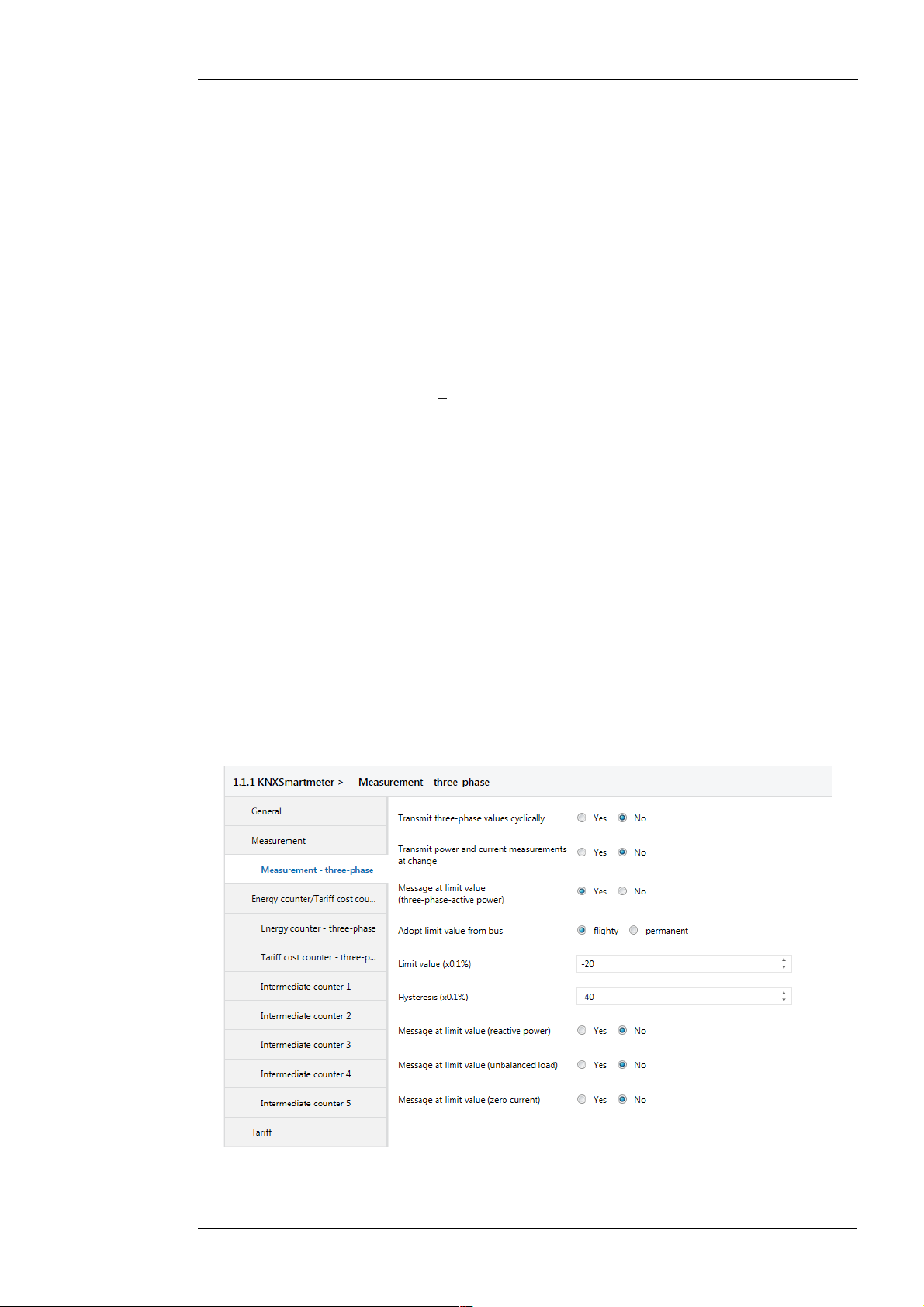
In the next tab “Measurement - three-phase values” the limit value of the three-phase active
power for load management is parametrized. In principle the concept of load control is to work
as follows:
If currently more energy is generated in the PV system than is consumed by the consumer loads
at home, then the Smartmeter will measure a negative three-phase active power. Then energy is
fed into the grid. In the opposite case the measured active power would be positive. The load
management is to be designed so, that only the excess energy from the PV-system will be used
for additional consumer loads. Therefore corresponding consumer loads have to be switched on
as soon as the active power reaches a certain negative value. This threshold is determined on
-966W in the example. If the active power becomes positive again, the consumer loads will be
switched off again. Therefore this threshold is set to 0W. Between these two thresholds a buffer
zone should be parametrized so that consumer loads do not continuously switched on or off.
Enertex® Bayern GmbH – Ebermannstädter Straße 8 - 91301 Forchheim - Deutschland - mail@enertex.de
Page 18
Handbuch-KnxSmartmeter-85A-en-3.odt, 2018-10-04 Seite 18 von 69
35A⋅−2% ⋅3⋅230V =−483W
3⋅230V
35A⋅−4 % ⋅3⋅230V =−966W
−483W −
1
2
⋅−966W =0W
−483W
1
2
⋅−966W =−966W
This is realized by the hysteresis function.
With the following parametrization this concept can be implemented. The limit value for the
three-phase active power is set to “-20” (=-2%). This corresponds to the following power:
The value 35A corresponds to the parametrized reference current. The term
is required
to convert the reference current in a three-phase reference power. The value for the hysteresis
is set to “-40” (=-4%). This corresponds to the following power:
With the limit values and the hysteresis the following thresholds arise:
• Under threshold:
• Upper threshold:
If the three-phase active power reaches the upper threshold of -966W, the value 1 is transmitted
to the group object “Active power limit message” (ID:66). In contrast, if the three-phase active
power reaches the lower threshold of 0W, the value 0 is transmitted to the group object “Active
power limit message” (ID:66). Exactly these values of the group object “Active power limit
message” (ID:66).are needed for switching on/off a consumer load. So the “switching”-group
object of the switching actuator of a consumer load has to be linked to the group object “Active
power limit message” (ID:66) of the Smartmeter.
However, the connected consumer load has also be suitable for this automatic enabling or
disabling. Possibly suitable consumer loads are for example electric heatings, heat pumps,
boiler, cooling aggregates or charging devices.
A much less critical method than the automatic switching of consumer loads is just to have the
energy excess displayed. Thus the residents are signaled by a green signal lamp at which time
the current is cheap (green signal lamp on) or at which time the current is expensive (green
signal lamp off). For this purpose the group object “Active power limit message” has to be linked
to the group object of the switching actuator of the signal lamp.
For parametrization of the load management the following values have to be selected in the tab
“Measurement- three-phase”:
Figure 15: Settings „Measurement - three-phase“ Example 2
In the next tab “Energy counter/Tariff cost counter” in Figure 16 the applied counter are
Enertex® Bayern GmbH – Ebermannstädter Straße 8 - 91301 Forchheim - Deutschland - mail@enertex.de
Page 19
Handbuch-KnxSmartmeter-85A-en-3.odt, 2018-10-04 Seite 19 von 69
released. Since in this example only the three-phase consumption and its costs are to be
visualized, only the energy counter “Energy counter - three-phase”, the cost counter “tariff costs
counter 1” and “Tariff costs counter 2” are released. Furthermore 3 intermediate counter are
required to represent the energy consumption, the energy supply and the balancing energy over
the course of one day on the bus. Two other intermediate counter are used to represent the
daily energy supply costs and the daily compensation for electricity fed into the grid:
Figure 16: Settings „Energy counter/Tariff cost counter“ Example 2
In the following two tabs “Energy counter - three-phase” and “Tariff cost counter - three-phase”
no settings have to be made. Here the default values are used.
In the tab “Intermediate counter 1” the energy counter is configured to count the energy delivery.
For this purpose the “Input count value of the intermediate counter” has to be set to “Active
energy counter (consumption) - three-phase”. The count interval is set to “15min”. Furthermore
the setting “Transmit counter value before resetting” is enabled:
Figure 17: Setting „Intermediate counter 1“ Example 2
With this configuration the intermediate counter sums up the delivery of three-phase energy, that
is only the energy flux in positive power flux direction, each about 15 minutes and transmits this
sum on the bus at the end of the interval. After that the intermediate counter resets and starts
Enertex® Bayern GmbH – Ebermannstädter Straße 8 - 91301 Forchheim - Deutschland - mail@enertex.de
Page 20
Handbuch-KnxSmartmeter-85A-en-3.odt, 2018-10-04 Seite 20 von 69
again summarizing the delivery of energy. Thereby the time intervals are synchronized with the
day time, so that the counting intervals only start and end at times XX:00 (=every hour), XX:15
and XX:45. Finally the 3-phase energy delivery of the last 15 minutes is transmitted cyclically
after each quarter of an hour by this parametrization. Thereby the delivery of energy of
intermediate counter 1 is transmitted via the group object “Energy counter-previous value” on
the bus. The delivery of energy is transmitted in unit Wh.
Similarly the “Intermediate counter 2” is configured to transmit the energy fed into the grid every
15 minutes on the bus:
Figure 18: Settings „Intermediate counter 2“ Example 2
By selecting the counter value “ Active energy counter (generation) - three-phase” only the
energy flux is counted in negative power flux direction.
Finally in “Intermediate counter 3” the counter is configured for the balanced energy:
Figure 19: Settings „Intermediate counter 3“ Example 2
In contrast to the “Active energy counter (consumption)” and “Active energy counter
(generation)” the “Active energy counter (balance)” counts all the time. Its counter value can
increase or decrease, whereas the consumption counter only increase and the generation
counter only decrease. With the balancing counter neither the energy costs or the compensation
can be calculated. Nevertheless the course of the day of the balancing counter shall be
recorded, as seen directly from this, to what extend the purchase of an additional battery storage
for solar energy would be useful.
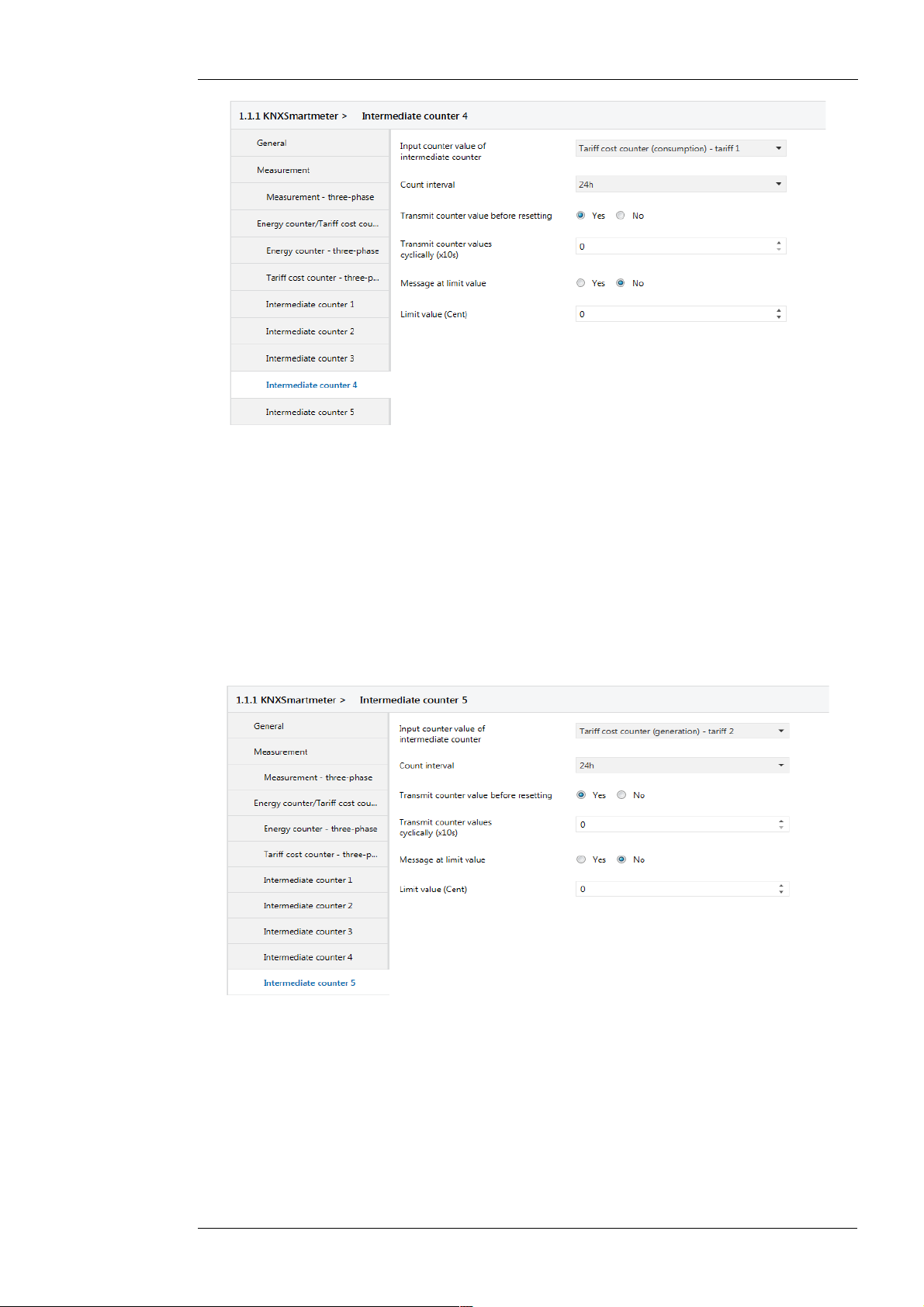
The “Intermediate counter 4” is used to calculate the daily energy delivery costs. As a counter
value it has to be used a “Tariff costs counter (consumption)”. Thus, this counter only counts,
when energy flows in positive power flux direction. As later in the example the delivery rate for
the current is deposited in the rate of tariff 1, the “Tariff costs counter (consumption) - tariff 1”
has to be used as a counter value:
Enertex® Bayern GmbH – Ebermannstädter Straße 8 - 91301 Forchheim - Deutschland - mail@enertex.de
Page 21
Handbuch-KnxSmartmeter-85A-en-3.odt, 2018-10-04 Seite 21 von 69
Figure 20: Settings „Intermediate counter 4“ Example 2
The counting interval is configured to 24 hours. Thus, the energy delivery costs are summed up
each over a day and transmitted to the bus via the group object “Cost counter-previous value” of
intermediate counter 4 at the end of the day. The transmitted value represents the daily energy
delivery cost in cent.
Similarly, the “Intermediate counter 5” is used to sum up the daily compensation and to transmit
on the bus. To calculate the compensation only the energy flux in negative power flux direction
may be used. Therefore a “Tariff cost counter (generation)” is necessary here, which only counts
on negative power flux direction.
Moreover this costs counter shall use the rate of tariff 2. In this tariff the compensation will be
specified ct/kWh in a later time. Therefore “Tariff cost counter (generation) - tariff 2” is selected
for the counter value:
Figure 21: Settings „Intermediate counter 5“ Example 2
As already mentioned, the rates for current delivery and for current feeding have to be provided
for the two cost counters. The specification have to be done under the heading “Tariff”. The
“Tariff 1” is used for the energy delivery tariff and the “Tariff 2” for the feed-in tariff. Therefore
these both tariffs are to release in the tab “Tariff”.
In the tab “Tariff 1” the current rate is indicated to 0.01 Cent/kWh. This means with e.g. a current
rate of 30ct/kWh a value of 3000 has to be specified here. Furthermore it has to be parametrized
here, when the tariff is to apply. In this simple example only a single current tariff should be
configured, which is valid around the clock. For this purpose the selection in “Tariff changeover
tariff 1” is selected to “always active”:
Enertex® Bayern GmbH – Ebermannstädter Straße 8 - 91301 Forchheim - Deutschland - mail@enertex.de
Page 22

Handbuch-KnxSmartmeter-85A-en-3.odt, 2018-10-04 Seite 22 von 69
Figure 22: Settings „Tariff 1“ Example 2
Similarly, the feed-in tariff is specified in the panel rate of “tariff 2”. To count positive income a
negative rate may be indicated here. In this case the active energy counter (generation) - threephase, which always contains, by definition, a negative value, is multiplied by a negative rate. It
results in a positive yield, which, for example, represents the yield of a PV-system. Therefore the
entering of the feed-in compensation of 11.56ct has a negative sign:
Figure 23: Settings „Tariff 2“ Example 2
Generally also the feed-in rate is not depending on the time of day. Therefore the tariff switching
is deactivated by selecting of “always active”.
The parametrization which is presented in this section causes the Smartmeter to transmit the
following group objects: "Energy counter-previous value" for the intermediate counter 1 (ID:
105), "Energy counter-previous value" for the intermediate counter 2 (ID: 113), "Energy counterprevious value" for the intermediate counter 3 (ID: 121), "Cost counter-previous value" for the
intermediate counter 4 (ID: 131) and "Cost counter-previous value" for the intermediate counter
5 (ID: 139).
Enertex® Bayern GmbH – Ebermannstädter Straße 8 - 91301 Forchheim - Deutschland - mail@enertex.de
Page 23

If these group objects are linked with group addresses, then they can be easily visualized in a
V =10
x− 253
80
time-diagram.
Measurement quantities
In this section an overview of the measurement quantities is given, which are measured by the
Smartmeter. In the following table also the data type is specified, with which the group object
can be processed in the Enertex EibPC. The definition of the sign of the power and the power
factor is shown in Figure 24.
Description of the measurement quantities:
Handbuch-KnxSmartmeter-85A-en-3.odt, 2018-10-04 Seite 23 von 69
Name KNX Data
type (dpt.)
Frequency 14.033 DPT_
Value_Frequenc
y in Hz
Voltage 9.020 DPT_
Value_Volt
in mV
Current 9.021 DPT_
Value_Curr
in mA
Active Power 14.056 DPT_
Value_Power
in W
Reactive Power 14.056 DPT_
Value_Power
in Var
Apparent Power 14.056 DPT_
Value_Power
in VA
Power Factor 14.057 DPT_
Value_Power_F
actor
without unit
Spectrum-U DPT_Harmonics
without unit
Data type
Description
for Enertex
EibPC
f32 in Hz Instantaneous frequency of grid.
f16 in mV Instantaneous voltage as a root mean square (RMS).
f16 in mA Instantaneous current as a root mean square (RMS). The
f32 in W Instantaneous active power.
f32 in Var Instantaneous reactive power.
f32 in VA Instantaneous apparent power.
f32 without
unit
u08 without
unit
The frequency is determined from the voltage of channel 1.
effective value is always positive, because it has no direction.
Active power is the real consumed energy per unit time. It may
be positive (during Energy consumption) or negative (during
Energy generation). Refer to Figure 24.
Reactive power is the exchanging energy between capacitance
and inductance . It can be positive (inductive) or negative
(capacitive). See also Figure 24.
Apparent power is the value resulting from active and reactive
power. This is always positive. With the apparent power the
utilization of resources such as cables or transformers can be
assessed.
Instantaneous power factor.
The power factor (cos φ) is the ratio of active power to apparent
power. The sign is defined in Figure 24.
Harmonics (0. to 50.) of the voltage . Since the recording of the
test series takes a minute, the values correspond to the
harmonics one minute ago.
When transmitting a complete spectrum, four single messages
with each 14 Bytes are transmitted. In them all the harmonics of
a voltage are coded as follows:
The first byte corresponds to an index of a harmonic; i.e. an
integer number between 0 and 50. The second byte is the
amount of the harmonic corresponding to the index from the first
byte. The following 12 bytes correspond to the amount of the
next 12 harmonics. Thus, the values of 13 harmonics are
transmitted in a 14-byte message. To exploit the range of values
of a byte in an optimal way, the values of a byte are again
encoded.
For decoding, a byte needs to be interpreted as a positive
integer x (i.e. between 0 and 255) and according to the formula
it has to be converted into a corresponding value V which is the
ratio of the corresponding harmonic to the fundamental.
Spectrum-I DPT_Harmonics
without unit
Enertex® Bayern GmbH – Ebermannstädter Straße 8 - 91301 Forchheim - Deutschland - mail@enertex.de
Harmonics (0. to 50.) of the current. Since the recording of the
test series takes a minute, the values correspond to the
harmonics one minute ago. The coding of messages and the
values corresponds to the the spectrum-U
Page 24

Handbuch-KnxSmartmeter-85A-en-3.odt, 2018-10-04 Seite 24 von 69
THD-U 8.010 DPT_
Percent_V16
in 0.01 %
THD-I 8.010 DPT_
Percent_V16
in 0.01 %
Unbalanced load 8.010 DPT_
Percent_V16
in 0.01 %
Zero current 9.021 DPT_
Value_Curr
in mA
Active energy
counter (balance)
13.010 DPT_
ActiveEnergy
in Wh
Active energycounter
(consumption)
Active energy
counter
(generation)
Reactive energy
counter
13.010 DPT_
ActiveEnergy
in Wh
13.010 DPT_
ActiveEnergy
in Wh
[13.012] DPT_
ReactiveEnergy
in Varh
Tariff costs
counter (balance)
13.001 DPT_
Value_4_Count
in ct
Tariff costs
counter
(consumption)
Tariff costs
counter
(generation)
13.001 DPT_
Value_4_Count
in ct
13.001 DPT_
Value_4_Count
in ct
s16
in 0.01 %
Instantaneous total harmonic distortion of the voltage.
Percentage represents the ratio of the effective value of
harmonics to the effective value of the fundamental It is always
positive.
s16
in 0.01 %
Instantaneous total harmonic distortion of the current.
Percentage represents the ratio of the effective value of
harmonics to the effective value of the fundamental. It is always
positive.
s16
in 0.01 %
Instantaneous unbalanced load in the three-phase system.
Percentage describes the ratio of the negative sequence
component of the current o the positive sequence component of
the current. It is always defined as positive.
f16 in mA Instantaneous zero current in three-phase system as a root
mean square (RMS).
It is determined by in-phase addition (vectorial) of the currents of
all three channels. For three-phase connection the value
corresponds to the current in the neutral conductor.
s32 in Wh Instantaneous count held by the balancing counter.
In this counter the balance of the energy flow is counted. If it is
negative, for example, the energy flow in the negative direction
of the power count arrow is greater than the energy flow in the
positive direction.
s32 in Wh Instantaneous count of the consumption counter.
In this counter only the consumed energy, i.e. the energy flow in
positive direction of the power count arrow is counted.
The value represents the consumed energy and is always
greater than or equal to zero.
s32 in Wh Instantaneous count of the generation counter.
In this counter only the generated energy, i.e. the energy flow in
negative direction of the power count arrow is counted.
The value represents the generated energy and is always less
than or equal to zero.
s32 in Varh Instantaneous count of the reactive energy counter.
In this counter the absolute value of the reactive power is
counted. The shown value is the absolute value of the reactive
power and therefore always positive.
s32 in ct Currently accounted costs in the corresponding tariff. This value
indicates the balance between consumption and generation
costs. The value can be positive or negative. If the value is
negative, the absolute value corresponds to a compensation.
s32 in ct Current costs for the consumed energy in the corresponding
tariff.
s32 in ct Current costs for the generated energy counted in the
corresponding tariff.
These costs are (at positive tariff-rate) negative and therefore
correspond to a compensation. The counter is used to a certain
extend for counting the compensation for the generated energy
in the corresponding tariff.
Enertex® Bayern GmbH – Ebermannstädter Straße 8 - 91301 Forchheim - Deutschland - mail@enertex.de
Page 25

Handbuch-KnxSmartmeter-85A-en-3.odt, 2018-10-04 Seite 25 von 69
φ
P
Q
positive active power =
consumption with respect
to the power count arrow
at current sensor
negative active power =
generation with respect
to the power count arrow
at current sensor
S
positive reactive power
consumed, inductive
positive active power
positive cos φ
consumed, capacitive
positive active power
positive cos φ
generated, inductive
negative active power
negative cos φ
generated, capacitive
negative active power
negative cos φ
negative reactive power
General Function Concepts
Cyclical transmitting
Measured values and counter readings can be transmitted cyclically on the bus. The function is
used as for equidistant representation of a measured value on the bus or in a diagram and thus
represents a sampling of the measured value.
When activated, the corresponding values are transmitted on the bus in a cycle time, which can
also be parametrized by ETS. The first transmission is carried out shortly after a restart of the
application. From this moment the value is transmitted cyclically. The transmissions are not
synchronized with day-time in this case.
If the cycle time 0 is given in the ETS, the value will never be transmitted cyclically.
Transmit at Change
Measurement values and counter readings can be transmitted on the bus after a change. The
function is used for a complete representation of a measurement on the bus or in a diagram.
Since the measured values are only transmitted after a change this can be done with a minimal
strain of the bus. On the bus a maximum of one change of a measurement value per second
can be transmitted.
In the ETS it can be parametrized, at which change the value on the bus is retransmitted. This
value is indicated in percentage. The first transmission is always performed shortly after a restart
of the application. From this point a new value is transmitted in each case, if the measured value
has changed by more than the set percentage value relative to the value last transmitted on the
bus. It is independent of whether the value last transmitted has been transmitted due to the
function “Transmit cyclically”, “Transmit at change” or “Request measured values”.
Figure 24: Representation of the counter quadrant
Attention: In the setting “Transmit at change” it is to be noted that the last transmitted measured
value can vary from the actual current measurement value by up to the percentage value which
is parametrized in the ETS respectively. With the help of the adjustable percentage a suitable
compromise between the deviation of the indication from the current measured value and the
bus strain can be found.
If in the ETS the percentage is specified to 0% the value will never be transmitted on a change.
Enertex® Bayern GmbH – Ebermannstädter Straße 8 - 91301 Forchheim - Deutschland - mail@enertex.de
Page 26

Bidirectional Counter
P+
The device can be used as a bidirectional counter and as a balancing counter at the same time.
Bidirectional counter are always required when at the measurement point of the counter an
energy flow occurs in both directions and in addition the energy flow in one direction is different
billed as the energy flow in the opposite direction. This is the case e.g. during the operation of a
PV-system in a residential building. If the Smartmeter is installed at the house connection line
then the registers for both directions must be used.
For this purpose each energy counter of the Smartmeter (i.e. active energy counter-channel 1,
active energy counter-channel 2, active energy counter-channel 3 and active energy counter
three-phase) has three registers. One register for the consumption (group object “Active energy
counter (consumption)”), one register for the generation (group object “Active energy counter
(generation)”) and one register for the balance (group object “ Active energy counter (balance)”).
The register for the consumption only counts, when an energy flow occurs in positive power flow
direction. The register for the generation only counts, when an energy flow occurs in negative
power flow direction. The register for the balance counts in both cases.
The power arrow direction is determined by the orientation of the current sensors. The power
arrow which is glued on the current sensors
Typically the current sensors are mounted so that the power arrow is oriented from the energy
source to the energy consumer load. This means that in the example of the installation of the
counter at the connection line of the residential home the current sensors are oriented so, that
the power arrow shows from the national grid to the consumer loads in the residential home. If
energy is currently consumed in the house, then the consumption counter counts in that case. If
in the house energy is never generated, the generation counter is always zero. If in the house
energy can be generated, e.g. by a PV-facility, then different scenarios are possible:
Handbuch-KnxSmartmeter-85A-en-3.odt, 2018-10-04 Seite 26 von 69
indicates the positive power arrow direction.
Scenario
More energy is consumed
than generated in the house.
More energy is generated
than consumed in the house.
As much as energy is
consumed as generated in the
house.
Consumer
counter
counting not counting Energy is charged by the supply rate of
not counting counting Energy is charged by the feed-in tariff
not counting not counting Nothing is charged.
Generation
counter
Consequence
the energy provider.
of the energy provider.
The “Active energy counter (balance)” also counts in the first both scenarios. For the charge of
the energy delivery only the value of the “Active energy counter (consumption)” is used.
However,for the charge of the compensation only the value of the “Active energy counter
(generation)” is used.
The “Active energy counter (generation)” is by definition always negative, since it is a negative
energy flow related to the power count arrow. With this definition it is always :
Active energy counter (balance) = Active energy counter (consumption) + Active energy counter
(generation)
Just as the energy counters each tariff costs counter has three registers for consumption,
generation and balance. They are treated in the same way, i.e. during an energy consumption
the tariff cost counter counts in the group object “Tariff costs counter (consumption)”, during an
energy generation the tariff cost counter counts in the group object “ Tariff costs counter
(generation)” and the tariff cost counter in the group object “ Tariff costs counter (balance)”
always counts.
Thus with regard to the costs separate registers are also used for each count direction. To count
a compensation directly in a cost counter, the feed-in tariff in tariff 1 can be specified. In the
group object "Tariff costs counter (generation)” for tariff 1 one can directly read the accumulated
compensation. In order that the compensation in the counter appears positive, a negative rate
(=compensation) has to be specified in the panel for the rate of tariff 1. If also energy delivery
costs are to be counted , the delivery rate of the supplier of electric energy can be indicated in
tariff 2. In the group object "Tariff costs counter (consumption)" for tariff 2 the accumulated
current costs can be read directly. The group object "Tariff costs counter (consumption)" for tariff
Enertex® Bayern GmbH – Ebermannstädter Straße 8 - 91301 Forchheim - Deutschland - mail@enertex.de
Page 27

2 can be ignored in this case.
Intermediate Counter
Intermediate counter are used to display energy consumptions and energy costs on the bus or in
a diagram.
An intermediate counter accumulates (sums) in each case a selectable count value over a
configurable time interval. This counter value may be an energy consumption, an energy
generation, an energy cost value or a compensation for electricity fed into the grid. The counter
value and the counting interval are configured in the ETS. The counting interval of the
intermediate counter is thereby synchronized with the daytime, so that, for example, an
accumulation of energy values for one hour always starts on the hour.
In detail an intermediate counter operates as follows:
After restarting the application the selected counter value is accumulated (summed) in the
current value of the intermediate counter, that is group object “Current value”. This accumulation
is carried out up to the first interval limit. Since the interval limits are synchronized with the
daytime, one time has to be transmitted to the corresponding group object “time” of the
Smartmeter (i.e. once after the restart of the application). To do this automatically, the function
"Request time and date after bus voltage recovery” can be used.
Attention: If the time is not transmitted to the Smartmeter, the interval limits cannot be detected
and the function of the intermediate counter (unless a manual trigger is used, see section below)
can not be used.
Handbuch-KnxSmartmeter-85A-en-3.odt, 2018-10-04 Seite 27 von 69
Once an interval limit is reached, the accumulated counter value is written from the group object
"Current value" into the group object "previous value". Thereafter the counter in the group object
"Current value" is reset to zero and the accumulation for the next interval starts again. If the
function “Transmit counter value before resetting” is activated, then at the interval limit the
counter value of the last count interval in the group object “previous value” is transmitted on the
bus. This feature allows for example the energy consumption of the last count interval in the
group object “previous value” to be transmitted on the bus at the end of each count interval. This
value can then be used to show the energy consumption over one day.
The intermediate counter additionally offers the option to set a count interval with a trigger. Thus,
it can be used without time. The function is activated by selecting of "By trigger object" in the
parameter count interval. As a trigger object the group object "Reset counters" is used. If in this
case the value “ON” is transmitted to the group object then this has the same effect as the
reaching of the interval limit in the case above. Thus, for example, it is possible to start a
consumption measurement by pressing a key button. By re-pressing the key button the energy
consumption, which is measured between the two manual operations, is transmitted on the bus.
Tariff Costs Counter
Tariff costs counters allow a representation of energy costs and energy yields on the bus or in a
diagram.
In contrast to the energy counters, which count energy in Wh, the tariff cost counters count the
energy costs in cent. Therefore the energy costs and accordingly energy yields have to be
indicated in 0.01ct/kWh. These costs and yields are deposited in up to three tariffs, which for
each tariff a rate and a time frame can be specified. Furthermore each tariff has three group
objects for tariff costs counter wherein in each case the costs for the active energy counter
(balance) - three-phase, active energy counter (consumption) - three-phase and active energy
counter (generation) - three-phase are counted. It should be noted that only the costs for threephase can be counted. The cost for the consumption in a single phase,for example, can not be
calculated in the Smartmeter.
A tariff costs counter counts each if the tariff is currently active and also the underlying (i.e.
either for balance, consumption or generation) three-phase energy counter counts. Due to the
set time frame for a tariff it can be determined, if it is currently active. It is also possible that
several tariffs are active at the same time. Then they count parallel.
To count positive yields, a negative rate can be specified. In this case the active energy counter
(generation) - three-phase, which always contains, by definition, a negative value, is multiplied
by a negative rate. The result is a positive yield which represents for example the yield of a PV-
Enertex® Bayern GmbH – Ebermannstädter Straße 8 - 91301 Forchheim - Deutschland - mail@enertex.de
Page 28

Handbuch-KnxSmartmeter-85A-en-3.odt, 2018-10-04 Seite 28 von 69
system.
Attention: If a tariff time switch is parametrized for a tariff and the time has not been transmitted
to the Smartmeter then the time frames for the tariffs can not be detected. In this case the tariff
is never active.
Tariffs can also be activated by trigger objects. The function is activated in the parameter “Tariff
changeover” by selecting “via triggering objects”. As trigger objects the group objects Trigger
(Tariff start)" and "Trigger (Tariff stop) can be used. If in this case the value “ON” is transmitted
to the group object “Trigger (Tariff start)", then the tariff is active. By transmitting the value “ON”
to the group object "Trigger (Tariff stop)" the tariff is deactivated again. In connection with the
limit value of the intermediate counter for example the costs of a volume tariff can be found. So
tariff 1 (low level tariff) can be stopped when a limit value for the three-phase energy counter
(consumption) is exceeded and tariff 2 (high level tariff) can be started. With the help of a
second threshold which has to be set to 0Wh tariff 2 can be stopped and tariff 1 can be
reactivated. With this configuration the two intermediate counter finally only have to be reset at
that time at which the volume will be newly “refreshed”. This can be done by a manual trigger.
In addition to the triggering of tariffs with the trigger objects the tariff can also be selected via the
group object “Tariff changeover”. Thereby “By trigger objects” has to be selected also in the
parameter “Tariff change”. Henceforward by transmitting the values 1, 2 or 3 the same tariff that
is tariff 1, tariff 2 or tariff 3 can be activated. If a tariff is enabled by these functions, then the
other both tariffs are disabled.
If the tariff selection by triggering objects is enabled then also the parameter “Tariff after bus
voltage recovery” is important. Here it can be parametrized which tariff is valid after restarting an
application. When selecting “as before” the device activates the same tariffs as last before
restarting.
If there is no tariff switching, the parameter “Tariff changeover” can be selected “always active”.
Then this tariff is always active and time is also not required. It is also possible to parametrize
two or three tariffs as always active. Then the current delivery costs can be counted in tariff
counter of tariff 1 and the compensation of a PV-system can be counted in tariff counter of tariff
2. For this purpose the electricity rate must be specified in tariff 1 and the compensation has to
be specified in tariff 2.
Furthermore the device offers the option to adopt the rate of a tariff from the bus via the group
object “Rate (0.01 ct/kWh)”. With this possibility the electricity rate can be easily adjusted via the
bus in case of a electricity rate change.
Preset of a Counter
Each counter can be preset with an energy value or rate. Thus, a count of the Smartmeter can
be matched with an existing counter. This allows easy control of the existing counter.
To preset a count only the “Writing”-flag of the corresponding group object of the counter has to
be set. Thereafter the counter can be rewritten via messages from the ETS. The written value
are given in Wh (not kWh). If necessary the “Writing”-flag of the corresponding group object can
then be removed again.
Message of limit values
In the application limits can be set for different measurement values. When these limits are
exceeded or fallen below corresponding messages are triggered on the bus. With this method
overloads, over voltages, under voltages, voltage drops, consumption peaks but also critical
values related to the grid quality can be reported on the bus. These messages can be used for
example for alarm messages or directly to initiate appropriate counteractions.
If a limit value is exceeded, the value 1 is transmitted to the corresponding group object “Limit
message”. However, if the limit value is fallen below the value 0 will be transmitted to the same
group object. The limit values are usually specified as absolute values. However, in the case of
currents and powers the limit values are indicated as percentages with respect to a reference
value. Thus, alarm messages such as "Alarm when exceeding 90% of the maximum allowable
current" can be parametrized literally. The value of the “maximum allowable current” has to be
parametrized in the parameter "Reference current for limit values" of the tab “Measurement”. It is
advisable that each of the backup value is used as a reference current with which the cables are
Enertex® Bayern GmbH – Ebermannstädter Straße 8 - 91301 Forchheim - Deutschland - mail@enertex.de
Page 29

Handbuch-KnxSmartmeter-85A-en-3.odt, 2018-10-04 Seite 29 von 69
secures at the measurement point of the Smartmeter. That means during the installation of the
Smartmeter for a 35A main fuse the reference value would be parametrized to 35A. The
reference value for the power limit is also determined by this parameter.
The reference value for a single-phase power limit is determined by the formula “Reference
current x 230”, the reference value for a three-phase power limit is determined by the formula
“Reference current x 230 x 3”. This means a parameter value of 7 would correspond to a
reference current of 35A, a single-phase reference power of 8050W and a three-phase
reference output of 24150W.
For the limit values of active and reactive power a hysteresis can also be set. This prevents a
flood of messages during a fluctuation of a measured value around the limit value (With limits
without hysteresis at most one message per second is transmitted at the bus in extreme cases).
Also the hysteresis is indicated in percent with respect to the above-mentioned reference value.
The setting of a hysteresis has the effect, that the value 1 is not transmitted to the limit value
until the measured value exceeds the value "parametrized limit value + 1/2 x parametrized
hysteresis value". Similarly, the value 0 is not transmitted until the measured value falls below
the value " parametrized limit value - 1/2 x parametrized hysteresis value".
Attention: If negative limit values are used at the power limits then by definition the values for
the hysteresis have also to be selected to be negative. In addition it should be noted that in case
of a negative limit value the value 1 is transmitted if the measured value exceeds the limit as an
absolute value. Similarly the value of 0 is transmitted if the measures value drops below the limit
as an absolute value.
Furthermore, limit values for counters can be realized. However, this is only possible for the socalled intermediate counter. As described in section “Intermediate Counter” an intermediate
counter has two group objects, of which the so called object "Energy counter-previous value"
always include the counter value of the last counting interval whereas the group object "Energy
counter-current value” is reset at the end of the counting interval and then again starts to count.
Within the counting interval, therefore, only the counter of the group object "Energy countercurrent value" counts. Hence the threshold is applied to this group object. Just as the object
"Energy counter-current value" also the object "Limit Message" of the intermediate counter is
reset at the end of the interval. This allows a transmission of the value 1 to the group object
"Limit message" in each count interval when a limit is exceeded, regardless of whether the limit
has been exceeded in the previous count interval.
The limits for the intermediate counters and the powers can also be changed by the bus via
corresponding group objects. Thus, a limit value, parametrized in the ETS can be overwritten by
that value, which has been transmitted to the group object. This allows, for example, the
individual setting of a limit value depending on specific conditions, for example in the daytime a
higher limit value can be used than in the night.
Recording on the SD card
Using the SD card measured data can be recorded. By the ETS the recording mode and the
recording interval can be parametrized. The recording modes are as follows:
Name Recording parameters
Energy consumption Over the time interval accumulated active energy for each channel and the three-
Current-/Voltage monitoring Voltage, Current, THD-U and THD-I for each channel,
All measured values without
harmonics
Harmonics Harmonics of voltage and current for each channel.
phase system (respectively active energy (balance), active energy (consumption),
active energy (generation)), over the time interval accumulated reactive energy for
the three-phase system
Number of the voltage and current peaks detected in the time interval for each
channel during the recording interval
All measured values from the mode "Energy consumption" and "Current-/Voltage
monitoring" and additional unbalanced load, line frequency and zero current.
By default the recording mode is set to "All measurements without harmonics". The recording
interval can be configured in steps 1min, 5min, 15min, 1h, 12h, and 24h.
After starting the application the recording to the SD-card starts. During the recording start a
new text file in csv-format is created on the SD-card, respectively. The file name is automatically
Enertex® Bayern GmbH – Ebermannstädter Straße 8 - 91301 Forchheim - Deutschland - mail@enertex.de
Page 30

Handbuch-KnxSmartmeter-85A-en-3.odt, 2018-10-04 Seite 30 von 69
generated from the recording mode and the recording day. A new recording file on the SD-card
is created for each day. In the first two lines of the log file it is a legend with name and unit for
the respective measured value of the corresponding column. the following lines contain the
recorded data. Each line starts with a time stamp indicating the time of recording of the
measured data record. The values in the data set represent the measured values in the previous
recording interval.(i.e.time to time stamp).
The recorded values are to be distinguished as follows:
Measurement value Interpretation Names in the legend
Active energy Accumulated active energy over the interval Ebal_Chx, Econ_Chx,
Reactive energy Accumulated amount of reactive energy over the
Voltage, Current Averaged rms over the interval U_Chx, I_Chx
Number of voltage peaks,
Number of current peaks
Total harmonic distortion of
voltage (THD-U), total harmonic
distortion of current (THD-I)
Active power, reactive power Averaged measured value over the interval. P_Chx, Q_Chx bzw. P_3ph,
Power factor Averaged measured value over the interval. Pf_Chx
Unbalanced load Averaged measured value over the interval.
Power frequency Averaged measured value over the interval. Freq_Ch1
Zero current Averaged measured value over the interval. I0_3ph
Harmonics of voltage Averaged measured value over the interval.
Harmonics of current Averaged measured value over the interval.
interval
Sum of all detected voltage or current peaks.
If a voltage value briefly exceeds the value of
650V, then this event is interpreted as a transient
voltage peak.
If a current value briefly exceeds the value of 140A
then this event is interpreted as a transient current
peak.
Averaged measured value over the interval.
Percentage is the effective value of the harmonics
with respect to the effective value of the
fundamental
Percentage represents the current of the negative
sequence system with respect to the current of
positive sequence system
Percentage represents the effective value of the
corresponding harmonics with respect to the
effective value of the fundamental
Percentage represents the effective value of the
corresponding harmonics with respect to the
effective value of the fundamental
Egen_Chx respective
Ebal_3ph, Econ_3ph,
Egen_3ph for three-phase
values
Ereact_3ph
NoUp_Chx, NoIp_Chx
ThdU_Chx, ThdI_Chx
Q_3ph for three-phase values
UnbalLoad_3ph
UhY_Chx, where Y is the
index of the harmonics. It is
between 0 (dc.) and 50.
IhY_Chx, where Y is the index
of the harmonics. It is
between 0 (dc.) and 50.
Here “_Chx” stands for the channels _Ch1, _Ch2 and Ch3, respectively. A log file can be
opened with a standard spreadsheet program. The presentation in a spreadsheet program, for
example, for the mode "Current-/Voltage monitoring" can look like this:
#Timestamp U_Ch1 U_Ch2 U_Ch3
NoUp
_Ch1
NoUp
_Ch2
NoUp
_Ch3
ThdU_Ch1 ThdU_Ch2
# [ISO 8601] [V] [V] [V] [ ] [ ] [ ] [%] [%]
2015-03-1218:15:00
2015-03-1218:30:00
2015-03-1218:45:00
228.72 229.72 228.02 0 1 2 99.60 0.12
228.52 229.52 228.12 0 0 0 99.60 0.1
228.62 229.72 228.02 1 0 1 99.60 0.06
Thereby the correct time and the correct date is shown in the time stamp, once (i.e. once after
the restart of the application) a time has to be transmitted to the group object “Time” and a date
has to be transmitted to the group object “Date” of the Smartmeter. To do this automatically after
Enertex® Bayern GmbH – Ebermannstädter Straße 8 - 91301 Forchheim - Deutschland - mail@enertex.de
Page 31

a restart of the application the function "Request time and date after bus voltage recovery" can
be used. If a time and a date has been transmitted to the Smartmeter then the recording is made
each synced with the time of the day, that means at a recording interval of 15 minutes the
recording is carried out in each case to the minute XX:00 (= every hour), to the minute XX:15, to
the minute XX:30 and to the minute XX:45.
If no time has been transferred to the Smartmeter by bus, then the clock is set to 00:00 when the
application starts and the first recording is performed after the elapse of the first recording
interval.
If at a time of recording no SD card is inserted then the recording data are lost for this time,
since the recording is not additionally buffered. If at the start of the application no SD card is
inserted, then the recording do not start until the first time of recording after insertion of the SD
card.
Attention: When the Smartmeter writes data to the SD card, the "POWER / SD-WRITE" LED
lights up red while writing. To prevent loss of data on the SD card, the SD card may not be
removed during the write operations.
Adjusting the real-time
clock without bus access
At a Smartmeter with RT option, the internal time of the smart meter can also be adjusted
without a KNX bus using only an SD card. Usually, the adjustment of the time is only necessary
after a few years, since the deviation of the internal time to the actual time increases only by a
maximum of one minute per year. The changeover from winter to summer time or from summer
to winter time is automatic, so there is no need to intervene manually. Likewise, leap years are
automatically taken into account in the date.
Handbuch-KnxSmartmeter-85A-en-3.odt, 2018-10-04 Seite 31 von 69
To readjust the time with an SD card, you must first create a text file with the date and time on it.
This text file must be created with the file name "DATETIME.TXT" (uppercase letters must be
used!). Then the file must be saved using a simple text editor, such as Editor or Wordpad. The
time to be set in the form of the time stamp, which is also used in the recording files, must now
be entered into the file. That For example, the text "2016-05-10-14:23:05" for May 10, 2016 and
the time of day of 14:23 and 5 seconds. To ensure that the time is interpreted correctly by the
Smartmeter, you must ensure that the time is entered exactly according to the specified pattern
and that no characters other than numbers, hyphen and colon are used. The SD card must now
be inserted into the Smartmeter during operation. As soon as the SD card is inserted, the time
stored on the SD card is taken over. The correct acceptance of the time is confirmed by the
yellow "POWER / SD-WRITE" LED lighting up for 2 seconds and then turning green again. To
set the time to the second with this method, the text file must specify a time in the future. The SD
card must then be inserted into the Smartmeter at exactly the specified time. If the time has
been taken over correctly, the file "DATETIME.TXT" will also be deleted automatically.
A smart meter with the RT option has an internal CR2032 lithium coin cell to maintain the clock
during power outages. The built-in battery lasts about 7 to 10 years if the device was not
disconnected from the 24V power supply for more than one year. If, after 7 to 10 years, there is
a large deviation in the time (more than 10 minutes), the internal battery must be replaced. The
exchange of the battery is only possible by opening the housing. To do this, the housing cover
must first be removed. This is snapped on the lower housing part and can be levered with a
screwdriver on the two provided notches on the cover. If the cover is removed, then the two
housing halves can be pulled apart. Finally, the lithium button cell in the battery clip can be
replaced.
Parameter
General
Note: Depending on the configuration, some settings may not be available. They are not shown
in the ETS in these cases.
Under the “General” tab the following settings can be made:
Enertex® Bayern GmbH – Ebermannstädter Straße 8 - 91301 Forchheim - Deutschland - mail@enertex.de
Page 32

Handbuch-KnxSmartmeter-85A-en-3.odt, 2018-10-04 Seite 32 von 69
Description of the parameters
Figure 25: General settings
Name Options Description
Transmission delay after bus voltage
recovery (s)
Transmission delay when sending
intermediate counter values(s)
Request time and date after bus voltage
recovery
Value of group object “Request time” [0 / 1] The value of the group object for time requesting can
Transmit group object “In operation” (s) [0,1...6535,
Value of group object “In operation” [0 / 1] The value of the group object “In operation” must be
[2-255] All messages that are transmitted after a bus voltage
2-255 All messages to be transmitted before the reset of
[Yes / No] After the bus voltage recovery the time and date can
0 = never
transmit]
recovery are delayed for this time. The device can
thus be configured so that transmission of objects
after the bus voltage recovery do not overload the
bus.
the intermediate counter are delayed for this time.
Thus the device can be configured so that
transmission of counts of the counter do not overload
the bus.
be obtained from the bus.
be parametrized.
The group object “In operation” can be transmitted
cyclically with the parametrized interval.
specified.
Enertex® Bayern GmbH – Ebermannstädter Straße 8 - 91301 Forchheim - Deutschland - mail@enertex.de
Page 33

Measurement
Handbuch-KnxSmartmeter-85A-en-3.odt, 2018-10-04 Seite 33 von 69
Under the tab “Measurement the following settings can be made:
Figure 26: Parameter Measurement
Description of the parameters:
Name Options Description
Reference current for limit values (x5A) [1,2 ... 134] All current limits assigning in percentage are based on
Release frequency Measurement [Yes / No] Release of parameters and group objects for the
Transmit frequency cyclically (x10s) [0,1,2...17280, 0
= not transmit
cyclically]
Transmit frequency at change (x0.1 Hz) [0..650, 0 = not
transmit when
changing]
SD card recording mode [Energy
consumption/
Current-,Voltage
monitoring/ All
measurement
values without
harmonics/
Harmonics]
SD card recording interval [- / 1min / 5min /
15min / 1h /
12h / 24h, "-" =
never recording]
the values set here. Power limits (or the corresponding
hysteresis values) in percentage are related to 230 x
reference current. Three-phase power limits (or the
corresponding hysteresis values) are related to 3 x 230
x reference current.
Example: When setting the value 17 the reference
current is 17 x 5A = 85A. A power limit of the channel
1 of 50% would then trigger at 9.975W (85A x 230V x
50% = 9.975W).
measurement of the frequency (measured from the
voltage of channel 1)
The group object with the measured frequency is
transmitted cyclically at intervals of the parametrized
value.
The group object with the measured frequency is
transmitted on a change to the configured value.
Mode indicates which measurements are recorded on
the SD card. See section Recording on the SD card for
the description of the recording modes.
In these intervals measured values incl. time stamp
are recorded on the SD card. As with the intermediate
counters the record timings are synchronized with the
time. See section Recording on the SD card for details
on the recording interval.
Enertex® Bayern GmbH – Ebermannstädter Straße 8 - 91301 Forchheim - Deutschland - mail@enertex.de
Page 34

Handbuch-KnxSmartmeter-85A-en-3.odt, 2018-10-04 Seite 34 von 69
Name Options Description
Release group object “Request measured
values”
Request measured values [0 / 1 / 0 or 1] The transmission of the measured values are
Release group object “Request power
values”
Request power values [0 / 1 / 0 or 1] The transmission of the measured values are
Release channel 1 [Yes / No] Release of the parameter and group objects for
Release channel 2 [Yes / No] Release of the parameter and group objects for
Release channel 3 [Yes / No] Release of the parameter and group objects for
Release three-phase values [Yes / No] Release of the parameter and group objects for
[Yes / No] The group object “Request measured values” is
released.
requested with a group object which has the value
parametrized here. When requesting all measured
values for current, voltage, THD-U, THD-I, Spectrum-I,
Spectrum-U, frequency and zero current are
transmitted on the bus, in which the function “Transmit
cyclically” is enabled.
[Yes / No] The group object “Request power values” can be
released.
requested with a group object which has the value
parametrized here. When requesting all measured
values for active power, reactive power, apparent
power, power factor and unbalanced load are
transmitted on the bus, in which the function “Transmit
cyclically” is enabled.
measurements of channel 1.
measurements of channel 2.
measurements of channel 3.
measurements of three-phase values.
Enertex® Bayern GmbH – Ebermannstädter Straße 8 - 91301 Forchheim - Deutschland - mail@enertex.de
Page 35

Handbuch-KnxSmartmeter-85A-en-3.odt, 2018-10-04 Seite 35 von 69
Settings under the tab „Measurement channel 1,2 or 3 (Part 1)“:
Figure 27: Parameter measurement channel 1 (Part 1)
Description of the parameters:
Name Options Description
Transmit power and voltage measurements
cyclically
Transmit measurements cyclically (x10s) [0,1,2...17280, 0 =
Transmit active power cyclically [Yes/ No] It is set whether the measured value for the
Transmit apparent power cyclically [Yes/ No] It is set whether the measured value for the
Transmit reactive power cyclically [Yes/ No] It is set whether the measured value for the
Enertex® Bayern GmbH – Ebermannstädter Straße 8 - 91301 Forchheim - Deutschland - mail@enertex.de
[Yes/ No] The parameters for cyclical transmission are
not transmit
cyclically]
hereby released.
The group objects with the measured values for
active-, reactive-, apparent power and voltage of
the channel 1, 2 or 3 are transmitted cyclically at
intervals of the parametrized value.
above-mentioned cycle time is transmitted.
above-mentioned cycle time is transmitted.
above-mentioned cycle time is transmitted.
Page 36

Handbuch-KnxSmartmeter-85A-en-3.odt, 2018-10-04 Seite 36 von 69
Name Options Description
Transmit voltage cyclically [Yes/ No] It is set whether the measured value for the
Transmit power, voltage and current
[Yes/ No] The parameters for transmission at change are
measurements at change.
Transmit measured values at change (in % of
[0, 1, ... 255] The group objects with the measured values for
the current measured value).
Transmit active power at change [Yes/ No] It is set whether the measured value is
Transmit apparent power at change [Yes/ No] It is set whether the measured value is
Transmit reactive power at change [Yes/ No] It is set whether the measured value is
Transmit voltage at change [Yes/ No] It is set whether the measured value is
Transmit current at change [Yes/ No] It is set whether the measured value is
Message at limit value (active power) [Yes/ No] When exceeding or falling below a threshold
Adopt limit value from bus [flighty /
permanent]
Limit value(x0.1%) [-1000 ... -1, 0,
+1 ... +1000]
Hysteresis (x0.1%) [-1000 ... -1, 0,
+1 ... +1000]
Message at limit value (voltage) [Yes/ No] When exceeding or falling below a limit value of
Limit value (V) [0, 1 ... 800] Limit value of the voltage of the channel.
above-mentioned cycle time is transmitted.
hereby released.
active-, reactive-, apparent power and voltage of
the channel 1, 2 or 3 are transmitted on a
change to the configured value.
transmitted when changing the above-mentioned
percentage value.
transmitted when changing the above-mentioned
percentage value.
transmitted when changing the above-mentioned
percentage value.
transmitted when changing the above-mentioned
percentage value.
transmitted when changing the above-mentioned
percentage value.
value of the active power of channel 1, 2 or 3, a
group object is transmitted. Release of the limit
parameters and the group object
See also section Message of limit values.
The limit overtaken by the bus will either be valid
only until the next reset or override the
configured value permanently.
Limit value of the active power of channel 1, 2 or
3. The limit is specified here as a percentage of
the reference power (=230 x reference current).
In case of negative limits it should be noted that
the value 1 is transmitted when the measured
value exceeds the limit by absolute value.
Similarly the value 0 is transmitted when the
measurement value drops below the limit by the
absolute value. See also section Message of
limit values
The limit value of the active power of channel 1,
2 or 3 has to be exceeded or fallen below at least
by the half value of the hysteresis, so that the
group object is transmitted. The value is given in
percent of the reference power. (=230V x
reference current). If the threshold is selected to
be negative, then the value for the hysteresis
has also by definition to be selected as negative.
the voltage on channel 1, 2 or 3, a group object
is transmitted. Release of a limit parameter and
the group object
Enertex® Bayern GmbH – Ebermannstädter Straße 8 - 91301 Forchheim - Deutschland - mail@enertex.de
Page 37

Handbuch-KnxSmartmeter-85A-en-3.odt, 2018-10-04 Seite 37 von 69
Settings under the tab „Measurement channel 1,2 or 3 (Part 2)“:
Figure 28: Parameter Measurement channel 1 (Part 2)
Description of the parameters
Name Options Description
Message at voltage failure (voltage) [Yes / No] At voltage outage (applies when Vac < 60Vrms) of
Message at transient voltage peak [Yes / No] In case of an appearance of a transient voltage
Transmit current and power quality
measurements cyclically
Enertex® Bayern GmbH – Ebermannstädter Straße 8 - 91301 Forchheim - Deutschland - mail@enertex.de
[Yes / No] The parameter for cyclically transmission are
the channel a group object is transmitted. If
60Vrms is exceeded, 0 is transmitted, If 60Vrms
is fallen below , 1 is transmitted. Release of the
group object.
spike with a peak value min. 650V a group object
is transmitted. Release of the group object.
Transient voltages (operations) are not
predictable (at random) and of a limited duration.
They are not repeated periodically and their shape
can not be clearly predict. Transient voltage
spikes can be caused e.g. by lightning strikes or
by triggering a fuse or a circuit breaker.
hereby released.
Page 38

Handbuch-KnxSmartmeter-85A-en-3.odt, 2018-10-04 Seite 38 von 69
Name Options Description
Transmit measurements cyclically (x10s) [0,1,2...17280] The group objects with the below-mentioned
Transmit current cyclically [Yes / No] It is set whether the measured value is
Transmit power factor cyclically [Yes / No] It is set whether the measured value is
Transmit THD-U cyclically [Yes / No] It is set whether the measured value is
Transmit THD-I cyclically [Yes / No] It is set whether the measured value is
Transmit spectrum U cyclically [Yes / No] It is set whether the measured value is
Transmit spectrum I cyclically [Yes / No] It is set whether the measured value is
Message at limit value (current) [Yes / No] When exceeding or falling below a threshold value
Limit value (x0.1%) [0, 1, 2 ... 1000] Limit value of the current on channel 1, 2 or 3,
Message at transient current peak [Yes / No] In case of an appearance of a transient current
Message at limit value (THD-U) [Yes / No] In case of exceeding or falling below of a limit
Limit value (x0.1%) [0, 1, ... 255] Limit value of THD-U on channel 1, 2 or 3.
Message at limit value (THD-I) [Yes / No] In case of exceeding or falling below of a limit
Limit value(x0.1%) [0, 1, ... 255] Limit value of THD-I on channel 1, 2 or 3.
measured values of channel 1, 2 or 3 are
transmitted cyclically in temporal distance of the
parametrized values
transmitted at the above-mentioned cycle time.
transmitted at the above-mentioned cycle time.
transmitted at the above-mentioned cycle time.
transmitted at the above-mentioned cycle time.
transmitted at the above-mentioned cycle time.
transmitted at the above-mentioned cycle time.
of the current on channel 1, 2 or 3 a group object
is transmitted. Release of the limit parameter and
the group object.
which shall be monitored. The limit is given here
as a percentage of the reference current. See also
section Message of limit values.
spike with a peak value min. 140A a group object
is transmitted. If 140A is exceeded 1 is
transmitted. Release of the group object.
Transient currents (operations) are not predictable
(at random) and of a limited duration. They are not
repeated periodically and their shape can not be
clearly predict. Transient current spikes can be
caused e.g. by lightning strikes or switching a
large capacity or a large transformer (Inrush).
value for THD-U on channel 1, 2 or 3, a group
object is transmitted. Release of the limit
parameter and the group object.
value for THD-I on channel 1, 2 or 3, a group
object is transmitted. Release of the limit
parameter and the group object.
Enertex® Bayern GmbH – Ebermannstädter Straße 8 - 91301 Forchheim - Deutschland - mail@enertex.de
Page 39

Handbuch-KnxSmartmeter-85A-en-3.odt, 2018-10-04 Seite 39 von 69
Settings under the tab “Measurement three-phase values “ (Part 1):
Figure 29: Parameter Measurement three-phase values (Part 1)
Description of parameters:
Name Options Description
Transmit three-phase values cyclically [Yes / No] The parameters for cyclically transmission are
Transmit values cyclically (x10s) [0,1,2...17280, 0 =
Transmit active power cyclically [Yes / No] It is set whether the measured value for the above-
Transmit apparent power cyclically [Yes / No] It is set whether the measured value for the above-
Transmit reactive power cyclically [Yes / No] It is set whether the measured value for the above-
Transmit zero current cyclically [Yes / No] It is set whether the measured value for the above-
Transmit unbalanced load cyclically [Yes / No] It is set whether the measured value for the above-
Transmit power and current
measurements at change
Transmit measured values at change
(in % of current measured value)
Transmit active power at change [Yes / No] It is set whether the measured value is transmitted
Transmit apparent power at change [Yes / No] It is set whether the measured value is transmitted
Transmit reactive power at change [Yes / No] It is set whether the measured value is transmitted
Transmit zero current st change [Yes / No] It is set whether the measured value is transmitted
not transmit
cyclically]
[Yes / No] The parameters for transmission at change are
[0, 1, ... 255] The group objects with the measured values for
hereby released.
The group objects with the measured values of the
three-phase variables are transmitted cyclically at
intervals of the parametrized value.
mentioned cycle time is transmitted.
mentioned cycle time is transmitted.
mentioned cycle time is transmitted.
mentioned cycle time is transmitted.
mentioned cycle time is transmitted.
hereby released.
active, reactive apparent power and zero current are
transmitted on a change to the configured value.
when changing the above-mentioned percentage
value.
when changing the above-mentioned percentage
value.
when changing the above-mentioned percentage
value.
when changing the above-mentioned percentage
value.
Enertex® Bayern GmbH – Ebermannstädter Straße 8 - 91301 Forchheim - Deutschland - mail@enertex.de
Page 40

Handbuch-KnxSmartmeter-85A-en-3.odt, 2018-10-04 Seite 40 von 69
Settings under the tab “Measurement three-phase values “ (Part 2):
Figure 30: Parameter Measurement three-phase values (Part 2)
Description of parameters:
Name Options Description
Message at limit value (three-phase active
power)
Adopt limit value from bus [flighty / permanent] The limit adopted by the bus will either be valid only
Limit value (x0.1%) [-1000 ... -1, 0,
Hysteresis (x0.1%) [-1000 ... -1, 0,
Message at limit value (reactive power) [Yes / No] When exceeding or falling below a threshold value
[Yes / No] When exceeding or falling below a threshold value
+1 ... +1000]
+1 ... +1000]
of the three phase active power a group object is
transmitted. Release of the limit parameter and the
group object.
until the next reset or override the configured value
permanently.
Limit of the three phase active power. The limit here
is specified as a percentage of the three phase
reference power (= 3 x 230 x reference current). In
case of negative limits it should be noted that the
value 1 is transmitted when the measured value
exceeds the limit as an absolute value. Similarly the
value 0 is transmitted when the measured value
drops below the limit as an absolute value. See.
also section Message of limit values
The limit of the three-phase active power has to be
exceeded or fallen below by at least half the value
of the hysteresis so that the group object is
transmitted. The limit here is specified as a
percentage of the three-phase reference power (= 3
x 230 V x reference current). If the threshold is
selected to be negative, then also the value for the
hysteresis has to be selected by definition as
negative.
of the three-phase reactive power a group object is
transmitted. Release of the limit parameter and of
the group object.
Enertex® Bayern GmbH – Ebermannstädter Straße 8 - 91301 Forchheim - Deutschland - mail@enertex.de
Page 41

Handbuch-KnxSmartmeter-85A-en-3.odt, 2018-10-04 Seite 41 von 69
Name Options Description
Limit value (x0.1%) [-1000 ... -1, 0,
+1 ... +1000]
Hysteresis (x0.1%) [-1000 ... -1, 0,
+1 ... +1000]
Message at limit value (unbalanced load) [Yes / No] When exceeding or falling below the limit value for
Limit value (%) [0, 1, ... 100] Limit for the unbalanced load.
Message at limit value (zero current) [Yes / No] When exceeding or falling below the limit value for
Limit value (x0.1%) [-1000 ... -1, 0,
+1 ... +1000]
Limit of the three-phase reactive power. The limit
here is specified as a percentage of the three phase
reference power (= 3 x 230 x reference current). In
case of negative limits it should be noted that the
value 1 is transmitted when the measured value
exceeds the limit as an absolute value. Similarly the
value 0 is transmitted when the measured value
drops below the limit as an absolute value. See.
also section Message of limit values
The limit of the three-phase active power has to be
exceeded or fallen below by at least half the value
of the hysteresis so that the group object is
transmitted. The limit here is specified as a
percentage of the three-phase reference power (= 3
x 230 V x reference current). If the threshold is
selected to be negative, then also the value for the
hysteresis has to be selected by definition as
negative.
the unbalanced load a group object is transmitted.
Release of the limit parameter and of the group
object.
the zero current a group object can be transmitted.
Release of the limit parameter and the group
object..
Limit value for the zero current. The limit is given
here as a percentage of the reference current. See
also section Message of limit values
Energy counter / Tariff cost counter
Under the tab “Energy counter / tariff counter” the following settings can be made:
Enertex® Bayern GmbH – Ebermannstädter Straße 8 - 91301 Forchheim - Deutschland - mail@enertex.de
Page 42

Handbuch-KnxSmartmeter-85A-en-3.odt, 2018-10-04 Seite 42 von 69
Figure 31: Parameter Energy counter
Description of the parameters:
Name Options Description
Release energy counter - channel 1 [Yes / No] The release of the parameters and group objects for
Release energy counter - channel 2 [Yes / No] The release of the parameters and group objects for
Release energy counter - channel 3 [Yes / No] The release of the parameters and group objects for
Release energy counter - three-phase [Yes / No] The release of the parameters and group objects for
Release tariff cost counter - three-phase [Yes / No] The release of the parameters for the groups “Tariff
Release tariff counter 1 [Yes / No] The group objects and the parameters for tariff cost
Release tariff counter 2 [Yes / No] The group objects and the parameters for tariff cost
Release tariff counter 3 [Yes / No] The group objects and the parameters for tariff cost
Release intermediate counter 1 [Yes / No] The release of the parameters and group objects for
Release intermediate counter 2 [Yes / No] The release of the parameters and group objects for
Release intermediate counter 3 [Yes / No] The release of the parameters and group objects for
Release intermediate counter 4 [Yes / No] The release of the parameters and group objects for
Release intermediate counter 5 [Yes / No] The release of the parameters and group objects for
Release intermediate counter 6 [Yes / No] The release of the parameters and group objects for
the energy counter of channel 1. For the operation of
energy counters see also section Bidirectional
Counter.
the energy counter of channel 2 For the operation of
energy counters see also section Bidirectional
Counter.
the energy counter of channel 3. For the operation of
energy counters see also section Bidirectional
Counter.
the groups “Energy counter - three-phase” and “Tariff
cost counter - three-phase values”. For the operation
of energy counters see also section Bidirectional
Counter.
cost counter - three-phase” and the parameter “Tariff
cost counter - 1, 2, 3”. For the operation of tariff cost
counters see also section Tariff Costs Counter.
counter tariff 1 (balance), tariff cost counter tariff 1
(consumption), tariff cost counter tariff 1 (generation)
are hereby released.
counter tariff 2 (balance), tariff cost counter tariff 2
(consumption), tariff cost counter tariff 2 (generation)
are hereby released.
counter tariff 3 (balance), tariff cost counter tariff 3
(consumption), tariff cost counter tariff 3 (generation)
are hereby released.
the group “Intermediate counter 1”.
the group “Intermediate counter 2”.
the group “Intermediate counter 3”.
the group “Intermediate counter 4”.
the group “Intermediate counter 5”.
the group “Intermediate counter 6”.
Enertex® Bayern GmbH – Ebermannstädter Straße 8 - 91301 Forchheim - Deutschland - mail@enertex.de
Page 43

Handbuch-KnxSmartmeter-85A-en-3.odt, 2018-10-04 Seite 43 von 69
Settings under the tab “Energy counter channel 1, 2 or 3”:
Figure 32: Parameter Energy counter channel 1
Description of the parameters:
Name Options Description
Transmit counter values cyclically [Yes / No] The parameters for cyclically transmission are
Transmit counter values cyclically (x10s) [0,1,2...17280, 0 =
Transmit cyclically active energy counter
(balance)
Transmit cyclically active energy counter
(consumption)
Transmit cyclically active energy counter
(generation)
Transmit counter values at change [Yes / No] The parameter for transmission and change are
Transmit counter values at change (in % of
current measured value)
Transmit at change active energy counter
(balance)
Transmit at change active energy counter
(consumption)
Transmit at change active energy counter
(generation)
Counter after ETS download [no reaction / reset] It is set whether the counters are reset after an
Release group object “Reset counter values
of channel 1 (channel 2 or channel 3)
not transmit
cyclically]
[Yes / No] It is set, whether the counter value is transmitted
[Yes / No] It is set, whether the counter value is transmitted
[Yes / No] It is set, whether the counter value is transmitted
[0, 1, ... 255, 0 = no
transmission at
change]
[Yes / No] It is set whether the counter value is transmitted
[Yes / No] It is set whether the counter value is transmitted
[Yes / No] It is set whether the counter value is transmitted
[Yes / No] The group object “Reset counters 1, 2 or 3” is
hereby released.
The group objects for the below-mentioned
counter values are transmitted cyclically at
intervals of the parametrized value.
at above-mentioned cycle time
at above-mentioned cycle time
at above-mentioned cycle time
hereby released.
The group objects for the below-mentioned
counter values are transmitted at change to the
configured value.
at change of the above-mentioned percentage
value.
at change of the above-mentioned percentage
value.
at change of the above-mentioned percentage
value.
ETS download.
released.If ON is transmitted to this object then
the three counter values for balancing energy
counter, consumption counter and generation
counter for channel 1, 2 or 3 are reset.
Enertex® Bayern GmbH – Ebermannstädter Straße 8 - 91301 Forchheim - Deutschland - mail@enertex.de
Page 44

Handbuch-KnxSmartmeter-85A-en-3.odt, 2018-10-04 Seite 44 von 69
Settings under the tab “Energy counter three-phase values”:
Figure 33: Parameter Energy counter three-phase values
Description of the parameters:
Name Options Description
Transmit counter values cyclically [Yes / No] The parameters for cyclical transmission are
Transmit counter values cyclically (x10s) [0,1,2...17280, 0
Transmit cyclically active energy counter
(balance)
Transmit cyclically active energy counter
(consumption)
Transmit cyclically active energy counter
(generation)
Transmit reactive energy counter cyclically [Yes / No] It is set whether the counter value of the above-
Transmit counter values at change [Yes / No] The parameters for transmission at are hereby
Transmit counter values at change (in % of
current measured value)
Transmit at change active energy counter
(balance)
Transmit at change active energy counter
(consumption)
Transmit at change active energy counter
(generation)
= not transmit
cyclically]
[Yes / No] It is set whether the counter value of the above-
[Yes / No] It is set whether the counter value of the above-
[Yes / No] It is set whether the counter value of the above-
[0, 1, ... 255, 0 =
no transmission
at change]
[Yes / No] It is set whether the counter value is transmitted at
[Yes / No] It is set whether the counter value is transmitted at
[Yes / No] It is set whether the counter value is transmitted at
hereby released.
The group objects for the below-mentioned counter
values are transmitted cyclically at intervals of the
configured value.
mentioned cycle time is transmitted.
mentioned cycle time is transmitted.
mentioned cycle time is transmitted.
mentioned cycle time is transmitted.
released.
The group objects with the below-mentioned
counter values are transmitted at change to the
parametrized value.
change of the above-mentioned percentage value.
change of the above-mentioned percentage value.
change of the above-mentioned percentage value.
Enertex® Bayern GmbH – Ebermannstädter Straße 8 - 91301 Forchheim - Deutschland - mail@enertex.de
Page 45

Handbuch-KnxSmartmeter-85A-en-3.odt, 2018-10-04 Seite 45 von 69
Name Options Description
Transmit reactive energy counter at change [Yes / No] It is set whether the counter value is transmitted at
Counter after ETS download [no reaction /
reset]
Release group object “Reset counter values” [Yes / No] The group object “Reset of counter values” is
change of the above-mentioned percentage value.
It is set whether the counter values of the threephase register are reset after an ETS download.
released. If an ON is transmitted to this object,
then the balancing active energy counter,
consumption counter and generation counter are
reset for the three-phase registers.
Under the tab “Tariff cost counter” the following settings can be made:
Figure 34: Parameter Tariff cost counter
Description of the parameters:
Name Options Description
Transmit tariff cost counter cyclically [Yes / No] The parameters for cyclical transmission are
Transmit cyclically (x10s) tariff cost
counter
Transmit cyclically tariff cost counter 1
(balance)
Transmit cyclically tariff cost counter 1
(con.)
Transmit cyclically tariff cost counter 1
(generation)
Transmit cyclically tariff cost counter 2
(balance)
Transmit cyclically tariff cost counter 2
(con.)
Enertex® Bayern GmbH – Ebermannstädter Straße 8 - 91301 Forchheim - Deutschland - mail@enertex.de
[0 to 172800, 0 =
not transmit
cyclically]
[Yes / No] It is set whether the measured value for the
[Yes / No] It is set whether the measured value for the
[Yes / No] It is set whether the measured value for the
[Yes / No] It is set whether the measured value for the
[Yes / No] It is set whether the measured value for the
hereby released
The group objects with the values of the balancing
tariff cost counters are transmitted cyclically at
intervals of the configured value.
above-mentioned cycle time is transmitted.
above-mentioned cycle time is transmitted.
above-mentioned cycle time is transmitted.
above-mentioned cycle time is transmitted.
above-mentioned cycle time is transmitted.
Page 46

Handbuch-KnxSmartmeter-85A-en-3.odt, 2018-10-04 Seite 46 von 69
Name Options Description
Transmit cyclically tariff cost counter 2
(generation)
Transmit cyclically tariff cost counter 3
(balance)
Transmit cyclically tariff cost counter 3
(con.)
Transmit cyclically tariff cost counter 3
(generation)
Release group object “Reset Tariff counter
values 1”
Release group object “Reset Tariff counter
values 2”
Release group object “Reset Tariff counter
values 3”
[Yes / No] It is set whether the measured value for the
above-mentioned cycle time is transmitted.
[Yes / No] It is set whether the measured value for the
above-mentioned cycle time is transmitted.
[Yes / No] It is set whether the measured value for the
above-mentioned cycle time is transmitted.
[Yes / No] It is set whether the measured value for the
above-mentioned cycle time is transmitted.
[Yes / No] The group object “Reset Tariff counter values 1” is
released.
[Yes / No] The group object “Reset Tariff counter values 2” is
released.
[Yes / No] The group object “Reset Tariff counter values 3” is
released.
Enertex® Bayern GmbH – Ebermannstädter Straße 8 - 91301 Forchheim - Deutschland - mail@enertex.de
Page 47

Handbuch-KnxSmartmeter-85A-en-3.odt, 2018-10-04 Seite 47 von 69
Settings under the tab “Intermediate counter 1-6”:
Figure 35: Parameter Intermediate counter 1
Description of the parameters:
Name Options Description
Input counter value of
intermediate counter
[Active energy counter (balance) - channel
1 / Active energy counter (consumption) channel 1 / Active energy counter
(generation) - channel 1 /
Active energy counter (balance) - channel
2 / Active energy counter (consumption) channel 2 / Active energy counter
(generation) - channel 2 /
Active energy counter (balance) - channel
3 / Active energy counter (consumption) channel 3 / Active energy counter
(generation) - channel 3 /
Active energy counter (balance) - threephase / Active energy counter
(consumption) - three-phase / Active
energy counter (generation) - threephase / Tariff cost counter (balance) tariff 1 / Tariff cost counter (consumption)
- tariff 1 / Tariff cost counter (generation) tariff 1 / Tariff cost counter (balance) tariff 2 / Tariff cost counter (consumption)
- tariff 2 / Tariff cost counter (generation) tariff 2 /
Tariff cost counter (balance) - tariff 3 /
Tariff cost counter (consumption) - tariff
3 / Tariff cost counter (generation) - tariff 3
/
Here the counted value can be selected which is
counted in the intermediate counter. An
intermediate counter is a counter that
automatically resets after a certain time. The final
counter value before resetting is written to the
group object “Intermediate counter - previous
value” and then, if parametrized, is transmitted on
the bus. See also section Intermediate Counter.
Enertex® Bayern GmbH – Ebermannstädter Straße 8 - 91301 Forchheim - Deutschland - mail@enertex.de
Page 48

Handbuch-KnxSmartmeter-85A-en-3.odt, 2018-10-04 Seite 48 von 69
Name Options Description
Count interval [1min, 5min, 10min, 15min, 1h, 12h, 24h,
Transmit counter
value before resetting
Transmit counter
values cyclically
(x10s)
Message at limit
value
Adopt limit value from
bus
Limit value (Wh) [-32767, -32766, ... -1, 0, 1 ... +32767] Limit of the intermediate counter. This parameter
Limit value(Cent) [-32767, -32766, ... -1, 0, 1 ... +32767] Limit of the intermediate counter. This parameter
1 week, via trigger object]
[Yes / No] After updating the group object “previous. value”
[0,1,2...17280, 0 = not transmit cyclically] The counter value of the group object “Current
[Yes / No] When exceeding or falling below the limit value of
[flighty / permanent] The limit value, adopted by the bus, can either be
The count interval can be selected here. After the
selected time the intermediate counter is reset.
Before resetting the current intermediate counter
reading is copied to the group object of the
previous value. The reset time instances of a
intermediate counter are synchronized with the
time, that is e.g.at time interval of 1 min the
counter is reset each when the second indicator
of the clock is 0. At 15 min counting interval the
counter value is reset corresponding to each
synchronized 1/4 hour, that is e.g. 00:00, 00:15,
00:30, 00:45.
Note: Since intermediate counters are
synchronized with the time, the counter readings
only reset at the defined times (and automatically
transmitted on the bus), if a time has been
transmitted to the group object “time” of the
Smartmeter.
If the value is set “on trigger object” then the
corresponding object is released. If in this case
the value ON is transmitted to the trigger group
object “Reset counter value”, then this has the
same effect as reaching the interval limit in the
above case.
at a count interval limit, this group object is
transmitted automatically on the bus. The
message is delayed in accordance with the
parameter of “General offset when transmitting
intermediate counter values”
value” can be transmitted cyclically.
the intermediate counter a group object can be
transmitted. Release of the limit parameter and of
the group object. See also section Message of
limit values
valid only until the next reset or override the
configured value permanently.
is only enabled when the counted value of the
intermediate counter is an energy counter.
is only enabled when the counted value of the
intermediate counter is a cost counter.
Tariff
Under the tab “Tariff” the following settings can be made:
Figure 36: Parameter Tariff
Enertex® Bayern GmbH – Ebermannstädter Straße 8 - 91301 Forchheim - Deutschland - mail@enertex.de
Page 49

Handbuch-KnxSmartmeter-85A-en-3.odt, 2018-10-04 Seite 49 von 69
Description of the parameters:
Name Options Description
Release tariff 1 [Yes / No] The release of the parameters and group
Release tariff 2 [Yes / No] The release of the parameters and group
Release tariff 3 [Yes / No] The release of the parameters and group
Tariff after bus voltage recovery [no tariff / Tariff 1 / Tariff 2 /
Tariff 3 / as before]
objects for the tariff 1 can be parametrized.
objects for the tariff 2 can be parametrized.
objects for the tariff 3 can be parametrized.
The valid tariff after bus voltage recovery or
restarting of the application can be
parametrized. The setting is effective only for
the tariffs, which are controlled “By trigger
objects”
Enertex® Bayern GmbH – Ebermannstädter Straße 8 - 91301 Forchheim - Deutschland - mail@enertex.de
Page 50

Handbuch-KnxSmartmeter-85A-en-3.odt, 2018-10-04 Seite 50 von 69
Settings under the tab “Tariff 1, 2 or 3”:
Figure 37: Parameter Tariff 1
Description of the parameters:
Name Options Description
Rate (0.01ct/kWh) [-10000,-9999... +10000] The kWh rate of tariff 1, 2 or 3 has to be
Adopt rate from bus [flighty / permanent] The rate can be overridden by an object. The
Tariff changeover tariff 1(2 ,3
respectively)
Start (hour) [0...23] The hour of the commencement of tariff 1, 2
Start (minute) [0...59] The minute of the commencement of tariff 1, 2
Start (weekday) [Mo/Tu/We/Th/Fr/Sa/Su/We
End (hour) [0...23] The hour of the end of tariff 1, 2 and 3,
End (minute) [0...59] The minute of the end of tariff 1, 2 and 3,
End (weekday) [Mo/Tu/We/Th/Fr/Sa/Su/We
[via tariff-time switch / via
triggering objects / always
active]
ekdays/Weekend/everyday]
ekdays/Weekend/everyday]
specified.
rate adopted by the bus, can either be valid
only until the next reset or override the
configured value permanently.
The tariff can be controlled either via the tariff
parameters (time) or trigger objects or always
be active. If “by trigger object” is selected then
the two group objects are enabled. With the
value “always active” no tariff switching takes
place. See section Tariff Costs Counter
and 3 ,respectively.
and 3, respectively.
The day of commencement of tariff 1, 2 and 3,
respectively.
respectively.
respectively.
The day of the end of tariff 1, 2 and 3,
respectively.
Enertex® Bayern GmbH – Ebermannstädter Straße 8 - 91301 Forchheim - Deutschland - mail@enertex.de
Page 51

Group Objects
Handbuch-KnxSmartmeter-85A-en-3.odt, 2018-10-04 Seite 51 von 69
Notes:
Depending on the configuration, some objects may not be available. Group objects, which
include measured variables, are described in detail in section Measurement quantities.
ID Name Object function Length Type Flags
0 General Power saving mode 1 bit [1.003]
DPT_Enable
The energy sensor can be switched via the KNX bus into the power saving mode. In power saving mode no
measurements are performed.
ID Name Object function Length Type Flags
1 General Time 3 Byte [10.001]
DPT_TimeOFDay
This time is used for the intermediate counter, tariff - time switch and the time stamp of the SD card log function. If
configured, the Smartmeter automatically requests the time using this group object after restarting the application
from the bus.
ID Name Object function Length Type Flags
162 General Date 3 Byte [11.001]
DPT_Date
This date is used for the intermediate counter, the tariff - time switch and the time stamp of the SD card log function. If
configured, the Smartmeter automatically requests the date using this group object after restarting the application
from the bus.
CRWT-
C-W-U
C-W-U
ID Name Object function Length Type Flags
2 General Request time 1 Bit [1.002]
DPT_Bool
The time of the Smartmeter can be requested by an other bus participant from the Smartmeter using this group
object.
ID Name Object function Length Type Flags
3 General In operation 1 Bit [1.002]
DPT_Bool
This group object can be transmitted cyclically to monitor the operation of the Smartmeter.
ID Name Object function Length Type Flags
4 Measurement Request measurements 1 Bit [1.002]
DPT_Bool
Using this group object all measured values can be requested excluding the performance values. At request only the
measured values are transmitted, in which the parameter “Transmit cyclically” has been activated.
ID Name Object function Length Type Flags
5 Measurement Request power values 1 Bit [1.002]
DPT_Bool
Using this group object all power values can be requested. At request only the power values are transmitted in which
“Transmit cyclically” has been activated.
ID Name Object function Length Type Flags
6 Measurement Frequency 4 Byte [14.033]
DPT_Value_Freque
ncy
Group object with the last measured power frequency
C--T-
C--T-
C-W--
C-W--
CR-T-
ID Name Object function Length Type Flags
7 Measurement
Ch1
Group object with the most recently determined RMS voltage of channel 1
Voltage (rms) 2 Byte [9.020]
DPT_Value_Volt
Enertex® Bayern GmbH – Ebermannstädter Straße 8 - 91301 Forchheim - Deutschland - mail@enertex.de
CR-T-
Page 52

Handbuch-KnxSmartmeter-85A-en-3.odt, 2018-10-04 Seite 52 von 69
ID Name Object function Length Type Flags
8 Measurement
Ch1
Current (rms) 2 Byte [9.021]
DPT_Value_Curr
CR-T-
Group object with the most recently determined RMS current of channel 1
ID Name Object function Length Type Flags
9 Measurement
Ch1
Active power 4 Byte [14.056]
DPT_Value_Power
CR-T-
Group object with the most recently determined active power of channel 1
ID Name Object function Length Type Flags
10 Measurement
Ch1
External active power limit 2 Byte [8.010]
DPT_Percent_V16
CRWT-
Limit value of the active power of channel 1. The value read is valid only if this object was written after a reset at least
once.
ID Name Object function Length Type Flags
11 Measurement
Ch1
Active power limit message 1 Bit [1.002]
DPT_Bool
C--T-
Group object, that is transmitted with the value 1 or 0, if the limit of the active power of channel 1 has been exceeded
or fallen below.
ID Name Object function Length Type Flags
12 Measurement
Ch1
Voltage limit message 1 Bit [1.002]
DPT_Bool
C--T-
Group object, that is transmitted with the value 1 or 0, if the limit of the voltage of channel 1 has been exceeded or
fallen below.
ID Name Object function Länge Typ Flags
13 Measurement
Ch1
Voltage failure message 1 Bit [1.002]
DPT_Bool
C--T-
Group object, that is transmitted with the value 1 or 0, if the voltage of channel 1 exceeds or falls below 60Vrms.
ID Name Object function Length Type Flags
14 Measurement
Ch1
Voltage peak message 1 Bit [1.002]
DPT_Bool
C--T-
Group object that transmits the value 1 if a transient voltage spike greater than 650V is detected at channel 1.
ID Name Object function Length Type Flags
15 Measurement
Ch1
Current limit message 1 Bit [1.002]
DPT_Bool
C--T-
Group object, that is transmitted with the value 1 or 0, if the limit of the current of channel 1 has been exceeded or
fallen below.
ID Name Object function Length Type Flags
16 Measurement
Ch1
Current peak message 1 Bit [1.002]
DPT_Bool
C--T-
Group object that transmits the value 1 if a transient current spike greater than 140A is detected at channel 1.
ID Name Object function Length Type Flags
17 Measurement
Ch1
THD-U limit message 1 Bit [1.002]
DPT_Bool
C--T-
Group object, that is transmitted with the value 1 or 0, if the limit of the THD-U of channel 1 has been exceeded or
fallen below.
Enertex® Bayern GmbH – Ebermannstädter Straße 8 - 91301 Forchheim - Deutschland - mail@enertex.de
Page 53

Handbuch-KnxSmartmeter-85A-en-3.odt, 2018-10-04 Seite 53 von 69
ID Name Object function Length Type Flags
18 Measurement
Ch1
THD-I limit message 1 Bit [1.002]
DPT_Bool
C--T-
Group object, that is transmitted with the value 1 or 0, if the limit of the THD-I of channel 1 has been exceeded or
fallen below.
ID Name Object function Length Type Flags
19 Measurement
Ch1
Apparent power 4 Byte [14.056]
DPT_Value_Power
CR-T-
Group object with the most recently determined apparent power of the channel1.
ID Name Object function Length Type Flags
20 Measurement
Ch1
Reactive power 4 Byte [14.056]
DPT_Value_Power
CR-T-
Group object with the most recently determined reactive power of the channel1.
ID Name Object function Length Type Flags
21 Measurement
Ch1
Power factor 4 Byte [14.057]
DPT_Value_Power
CR-T-
_Factor
Group object with the most recently determined power factor of the channel1.
ID Name Object function Length Type Flags
22 Measurement
Ch1
THD-U 2 Byte [8.010]
DPT_Percent_V16
CR-T-
Group object with the most recently determined THD-U of the channel1.
ID Name Object function Length Type Flags
23 Measurement
Ch1
THD-I 2 Byte [8.010]
DPT_Percent_V16
CR-T-
Group object with the most recently determined THD-I of the channel1.
ID Name Object function Length Type Flags
24 Measurement
Ch1
Spectrum-U 14 Byte New dpt-Type.
have not been
CR-T-
released yet by
KNX
Group object with the most recently determined values of the harmonics of the voltage of the channel 1.
Explanation see section Measurement quantities.
ID Name Object function Length Type Flags
25 Measurement
Ch1
Spectrum-I 14 Byte New dpt-Type.
have not been
CR-T-
released yet by
KNX
Group object with the most recently determined values of the harmonics of the current of the channel 1.
Explanation see section Measurement quantities.
ID Name Object function Length Type Flags
26 Measurement
Ch2
Voltage (rms) 2 Byte [9.020]
DPT_Value_Volt
CR-T-
Group object with the most recently determined rms value of the voltage of the channel 2.
ID Name Object function Length Type Flags
27 Measurement
Ch2
Current (rms) 2 Byte [9.021]
DPT_Value_Curr
CR-T-
Group object with the most recently determined rms value of the current of the channel 2.
Enertex® Bayern GmbH – Ebermannstädter Straße 8 - 91301 Forchheim - Deutschland - mail@enertex.de
Page 54

Handbuch-KnxSmartmeter-85A-en-3.odt, 2018-10-04 Seite 54 von 69
ID Name Object function Length Type Flags
28 Measurement
Ch2
Active power 4 Byte [14.056]
DPT_Value_Power
CR-T-
Group object with the most recently determined active power of the channel 2.
ID Name Object function Length Type Flags
29 Measurement
Ch2
External active power limit 2 Byte [8.010]
DPT_Percent_V16
CRWT-
Limit value of the active power of channel 2. The value read is valid only if this object was written after a reset at least
once.
ID Name Object function Length Type Flags
30 Measurement
Ch2
Active power limit message 1 Bit [1.002]
DPT_Bool
C--T-
Group object, that is transmitted with the value 1 or 0, if the limit of the active power of channel 2 has been exceeded
or fallen below.
ID Name Object function Length Type Flags
31 Measurement
Ch2
Voltage limit message 1 Bit [1.002]
DPT_Bool
C--T-
Group object, that is transmitted with the value 1 or 0, if the limit of the voltage of channel 2 has been exceeded or
fallen below.
ID Name Object function Length Type Flags
32 Measurement
Ch2
Voltage failure message 1 Bit [1.002]
DPT_Bool
C--T-
Group object, that is transmitted with the value 1 or 0, if the voltage at channel 2 exceeds or falls below 60Vrms.
ID Name Object function Length Type Flags
33 Measurement
Ch2
Voltage peak message 1 Bit [1.002]
DPT_Bool
C--T-
Group object that transmits the value 1 if at channel 2 a transient voltage spike greater than 650V is detected.
ID Name Object function Length Type Flags
34 Measurement
Ch2
Current limit message 1 Bit [1.002]
DPT_Bool
C--T-
Group object, that is transmitted with the value 1 or 0, if the limit of the current of channel 2 has been exceeded or
fallen below.
ID Name Object function Length Type Flags
35 Measurement
Ch2
Current peak message 1 Bit [1.002]
DPT_Bool
C--T-
Group object that transmits the value 1 if at channel 2 a transient current spike greater than 140A is detected.
ID Name Object function Length Type Flags
36 Measurement
Ch2
THD-U limit message 1 Bit [1.002]
DPT_Bool
C--T-
Group object, that is transmitted with the value 1 or 0, if the limit of the THD-U of channel 2 has been exceeded or
fallen below.
ID Name Object function Length Type Flags
37 Measurement
Ch2
THD-I limit message 1 Bit [1.002]
DPT_Bool
C--T-
Group object, that is transmitted with the value 1 or 0, if the limit of the THD-I of channel 2 has been exceeded or
fallen below.
ID Name Object function Length Type Flags
38 Measurement
Ch2
Apparent power 4 Byte [14.056]
DPT_Value_Power
Enertex® Bayern GmbH – Ebermannstädter Straße 8 - 91301 Forchheim - Deutschland - mail@enertex.de
CR-T-
Page 55

Handbuch-KnxSmartmeter-85A-en-3.odt, 2018-10-04 Seite 55 von 69
Group object with the most recently determined apparent power of the channel 2.
ID Name Object function Length Type Flags
39 Measurement
Ch2
Reactive power 4 Byte [14.056]
DPT_Value_Power
CR-T-
Group object with the most recently determined reactive power of the channel 2.
ID Name Object function Length Type Flags
40 Measurement
Ch2
Power factor 4 Byte [14.057]
DPT_Value_Power
CR-T-
_Factor
Group object with the most recently determined power factor of the channel 2.
ID Name Object function Length Type Flags
41 Measurement
Ch2
THD-U 2 Byte [8.010]
DPT_Percent_V16
CR-T-
Group object with the most recently determined THD-U of the channel 2.
ID Name Object function Length Type Flags
42 Measurement
Ch2
THD-I 2 Byte [8.010]
DPT_Percent_V16
CR-T-
Group object with the most recently determined THD-I of the channel 2.
ID Name Object function Length Type Flags
43 Measurement
Ch2
Spectrum-U 14 Byte New dpt-Type.
have not been
CR-T-
released yet by
KNX
Group object with the most recently determined values of the harmonics of the voltage of the channel 2.
Explanation see section Measurement quantities.
ID Name Object function Length Type Flags
44 Measurement
Ch2
Spectrum-I 14 Byte New dpt-Type.
have not been
CR-T-
released yet by
KNX
Group object with the most recently determined values of the harmonics of the current of the channel 2.
Explanation see section Measurement quantities.
ID Name Object function Length Type Flags
45 Measurement
Ch3
Voltage (rms) 2 Byte [9.020]
DPT_Value_Volt
CR-T-
Group object with the most recently determined RMS voltage of the channel 3.
ID Name Object function Length Type Flags
46 Measurement
Ch3
Current (rms) 2 Byte [9.021]
DPT_Value_Curr
CR-T-
Group object with the most recently determined RMS current of the channel 3.
ID Name Object function Length Type Flags
47 Measurement
Ch3
Active power 4 Byte [14.056]
DPT_Value_Power
CR-T-
Group object with the most recently active power of the channel 3.
ID Name Object function Length Type Flags
48 Measurement
Ch3
External active power limit 2 Byte [8.010]
DPT_Percent_V16
CRWT-
Limit value of the active power of channel 3. The value read is valid only if this object was written after a reset at least
once.
Enertex® Bayern GmbH – Ebermannstädter Straße 8 - 91301 Forchheim - Deutschland - mail@enertex.de
Page 56

Handbuch-KnxSmartmeter-85A-en-3.odt, 2018-10-04 Seite 56 von 69
ID Name Object function Length Type Flags
49 Measurement
Ch3
Active power limit message 1 Bit [1.002]
DPT_Bool
C--T-
Group object, that is transmitted with the value 1 or 0, if the limit of the active power of channel 3 has been exceeded
or fallen below.
ID Name Object function Length Type Flags
50 Measurement
Ch3
Voltage limit message 1 Bit [1.002]
DPT_Bool
C--T-
Group object, that is transmitted with the value 1 or 0, if the limit of the voltage of channel 3 has been exceeded or
fallen below.
ID Name Object function Length Type Flags
51 Measurement
Ch3
Voltage failure message 1 Bit [1.002]
DPT_Bool
C--T-
Group object, that is transmitted with the value 1 or 0, if the voltage at channel 3 exceeds or falls below 60Vrms.
ID Name Object function Length Type Flags
52 Measurement
Ch3
Voltage peak message 1 Bit [1.002]
DPT_Bool
C--T-
Group object that transmits the value 1 if at channel 3 a transient voltage spike greater than 650V is detected.
ID Name Object function Length Type Flags
53 Measurement
Ch3
Current limit message 1 Bit [1.002]
DPT_Bool
C--T-
Group object, that is transmitted with the value 1 or 0, if the limit of the current of channel 3 has been exceeded or
fallen below.
ID Name Object function Length Type Flags
54 Measurement
Ch3
Current peak message 1 Bit [1.002]
DPT_Bool
C--T-
Group object that transmits the value 1 if at channel 3 a transient current spike greater than 140A is detected.
ID Name Object function Length Type Flags
55 Measurement
Ch3
THD-U limit message 1 Bit [1.002]
DPT_Bool
C--T-
Group object, that is transmitted with the value 1 or 0, if the limit of the THD-U of channel 3 has been exceeded or
fallen below.
ID Name Object function Length Type Flags
56 Measurement
Ch3
THD-I limit message 1 Bit [1.002]
DPT_Bool
C--T-
Group object, that is transmitted with the value 1 or 0, if the limit of the THD-I of channel 3 has been exceeded or
fallen below.
ID Name Object function Length Type Flags
57 Measurement
Ch3
Apparent power 4 Byte [14.056]
DPT_Value_Power
CR-T-
Group object with the most recently determined apparent power of the channel 3.
ID Name Object function Length Type Flags
58 Measurement
Ch3
Reactive power 4 Byte [14.056]
DPT_Value_Power
CR-T-
Group object with the most recently determined reactive power of the channel 3.
Enertex® Bayern GmbH – Ebermannstädter Straße 8 - 91301 Forchheim - Deutschland - mail@enertex.de
Page 57

Handbuch-KnxSmartmeter-85A-en-3.odt, 2018-10-04 Seite 57 von 69
ID Name Object function Length Type Flags
59 Measurement
Ch3
Power factor 4 Byte [14.057]
DPT_Value_Power
CR-T-
_Factor
Group object with the most recently determined power factor of the channel 3.
ID Name Object function Length Type Flags
60 Measurement
Ch3
THD-U 2 Byte [8.010]
DPT_Percent_V16
CR-T-
Group object with the most recently determined THD-U of the channel 3.
ID Name Object function Length Type Flags
61 Measurement
Ch3
THD-I 2 Byte [8.010]
DPT_Percent_V16
CR-T-
Group object with the most recently determined THD-I of the channel 3.
ID Name Object function Length Type Flags
62 Measurement
Ch3
Spectrum-U 14 Byte New dpt-Type.
have not been
CR-T-
released yet by
KNX
Group object with the most recently determined values of the harmonics of the voltage of the channel 3.
Explanation see section Measurement quantities.
ID Name Object function Length Type Flags
63 Measurement
Ch3
Spectrum-I 14 Byte New dpt-Type.
have not been
CR-T-
released yet by
KNX
Group object with the most recently determined values of the harmonics of the current of the channel 3.
Explanation see section Measurement quantities.
ID Name Object function Length Type Flags
64 Measurement
three-phase
Active power 4 Byte [14.056]
DPT_Value_Power
CR-T-
Group object with the most recently determined three-phase active power
ID Name Object function Length Type Flags
65 Measurement
three-phase
External active power limit 2 Byte [8.010]
DPT_Percent_V16
CRWT-
Limit of three-phase active power. The value read is valid only if this object was written after a reset at least once.
ID Name Object function Length Type Flags
66 Measurement
three-phase
Active power limit message 1 Bit [1.002]
DPT_Bool
C--T-
Group object that is transmitted with the value 1 or 0, if the limit of the three-phase active power has been exceeded
or fallen below.
ID Name Object function Length Type Flags
67 Measurement
three-phase
Reactive power 4 Byte [14.056]
DPT_Value_Power
CR-T-
Group object with the most recently determined three-phase reactive power.
ID Name Object function Length Type Flags
68 Measurement
three-phase
External reactive power limit 2 Byte [8.010]
DPT_Percent_V16
CRWT-
Limit of three-phase reactive power. The value read is valid only if this object was written after a reset at least once.
Enertex® Bayern GmbH – Ebermannstädter Straße 8 - 91301 Forchheim - Deutschland - mail@enertex.de
Page 58

Handbuch-KnxSmartmeter-85A-en-3.odt, 2018-10-04 Seite 58 von 69
ID Name Object function Length Type Flags
69 Measurement
three-phase
Reactive power limit message 1 Bit [1.002]
DPT_Bool
CR-T-
Group object that is transmitted with the value 1 or 0, if the limit of the three-phase reactive power has been exceeded
or fallen below.
ID Name Object function Length Type Flags
70 Measurement
three-phase
Apparent power 4 Byte [14.056]
DPT_Value_Power
CR-T-
Group object with the most recently determined three-phase apparent power.
ID Name Object function Length Type Flags
71 Measurement
three-phase
Unbalanced load 2 Byte [8.010]
DPT_Percent_V16
CR-T-
Group object with the last determined unbalanced load.
ID Name Object function Length Type Flags
72 Measurement
three-phase
Unbalanced load limit message 1 Bit [1.002]
DPT_Bool
C--T-
Group object that is transmitted with the value 1 or 0, if the limit of the unbalanced load has been exceeded or fallen
below.
ID Name Object function Length Type Flags
73 Measurement
three-phase
Zero current 2 Byte [9.021]
DPT_Value_Curr
CR-T-
Group object with the most recently determined RMS value of zero current.
ID Name Object function Length Type Flags
74 Measurement
three-phase
Zero current limit message 1 Bit [1.002]
DPT_Bool
C--T-
Group object that is transmitted with the value 1 or 0, if the limit of the zero current has been exceeded or fallen
below.
ID Name Object function Length Type Flags
75 Energy counter
Ch1
Active energy counter (bal.) 4 Byte [13.010]
DPT_ActiveEnergy
CR-T-
Counter value of the balancing active energy counter of channel 1. The counter can be positive or negative. If the
value is negative, then the generated power was greater than the consumed energy.
ID Name Object function Length Type Flags
76 Energy counter
Ch1
Active energy counter (con.) 4 Byte [13.010]
DPT_ActiveEnergy
CR-T-
Counter value of the active energy counter (consumption) of channel 1. This counter value is always positive or 0.
ID Name Object function Length Type Flags
77 Energy counter
Ch1
Active energy counter (gen. 4 Byte [13.010]
DPT_ActiveEnergy
CR-T-
Counter value of the active energy counter (generation) of channel 1. This counter value is always negative or 0.
ID Name Object function Length Type Flags
78 Energy counter
Ch1
Reset counters 1 Bit [1.017]
DPT_Trigger
C-W--
The three counter values (balance, consumption and generation) can be reset to 0 via the group object.
ID Name Object function Length Type Flags
79 Energy counter
Ch2
Active energy counter (bal.) 4 Byte [13.010]
DPT_ActiveEnergy
Enertex® Bayern GmbH – Ebermannstädter Straße 8 - 91301 Forchheim - Deutschland - mail@enertex.de
CR-T-
Page 59

Handbuch-KnxSmartmeter-85A-en-3.odt, 2018-10-04 Seite 59 von 69
Counter value of the balancing active energy counter of channel 2. The counter can be positive or negative. If the
value is negative, then the generated power was greater than the consumed energy.
ID Name Object function Length Type Flags
80 Energy counter
Ch2
Active energy counter (con.) 4 Byte [13.010]
DPT_ActiveEnergy
CR-T-
Counter value of the active energy counter (consumption) of channel 2. This counter value is always positive or 0.
ID Name Object function Length Type Flags
81 Energy counter
Ch2
Active energy counter (gen.) 4 Byte [13.010]
DPT_ActiveEnergy
CR-T-
Counter value of the active energy counter (generation) of channel 2. This counter value is always negative or 0.
ID Name Object function Length Type Flags
82 Energy counter
Ch2
Reset counters 1 Bit [1.017]
DPT_Trigger
C-W--
The three counter values (balance, consumption and generation) can be reset to 0 via the group object.
ID Name Object function Length Type Flags
83 Energy counter
Ch3
Active energy counter (bal.) 4 Byte [13.010]
DPT_ActiveEnergy
CR-T-
Counter value of the balancing active energy counter of channel 3. The counter can be positive or negative. If the
value is negative, then the generated power was greater than the consumed energy.
ID Name Object function Length Type Flags
84 Energy counter
Ch3
Active energy counter (con.) 4 Byte [13.010]
DPT_ActiveEnergy
CR-T-
Counter value of the active energy counter (consumption) of channel 3. This counter value is always positive or 0.
ID Name Object function Length Type Flags
85 Energy counter
Ch3
Active energy counter (gen.) 4 Byte [13.010]
DPT_ActiveEnergy
CR-T-
Counter value of the active energy counter (generation) of channel 3. This counter value is always negative or 0.
ID Name Object function Length Type Flags
86 Energy counter
Ch3
Reset counters 1 Bit [1.017]
DPT_Trigger
C-W--
The three counter values (balance, consumption and generation) can be reset to 0 via the group object.
ID Name Object function Length Type Flags
87 Energy counter
three-phase
Active energy counter (bal. 4 Byte [13.010]
DPT_ActiveEnergy
CR-T-
Counter value of the balancing active energy counter of the three-phase values. The counter can be positive or
negative. If the value is negative, then the generated power was greater than the consumed energy.
ID Name Object function Length Type Flags
88 Energy counter
three-phase
Active energy counter (con.) 4 Byte [13.010]
DPT_ActiveEnergy
CR-T-
Counter value of the active energy counter (consumption) of he three-phase values. This counter value is always
positive or 0.
ID Name Object function Length Type Flags
89 Energy counter
three-phase
Active energy counter (gen.) 4 Byte [13.010]
DPT_ActiveEnergy
CR-T-
Counter value of the active energy counter (generation) of the three-phase values. This counter value is always
negative or 0.
Enertex® Bayern GmbH – Ebermannstädter Straße 8 - 91301 Forchheim - Deutschland - mail@enertex.de
Page 60

Handbuch-KnxSmartmeter-85A-en-3.odt, 2018-10-04 Seite 60 von 69
ID Name Object function Length Type Flags
90 Energy counter
three-phase
Reactive energy counter 4 Byte [13.010]
DPT_ActiveEnergy
CR-T-
Counter value of the reactive energy counter of he three-phase value. The counter value is always positive since only
the absolute value of the reactive energy is counted.
ID Name Object function Length Type Flags
91 Energy counter
three-phase
Reset counters 1 Bit [1.017]
DPT_Trigger
C-W--
The three counter values (balance, consumption, generation and reactive energy counter) can be reset to 0 via the
group object.
ID Name Object function Length Type Flags
92 Tariff counter 1-
three-phase
Tariff cost counter (balance) 4 Byte [13.001]
(4-Octed Signed)
CR-T-
values
The object contains the accumulated costs (in Cent) for the tariff 1. They are calculated from the three-phase active
energy (balance) counted in tariff 1 and from the rate of tariff 1. The costs can be positive or negative. If the
generated energy is greater than the consumed energy, then negative costs arise from that (=compensation).
ID Name Object function Length Type Flags
93 Tariff counter 1-
three-phase
values
Tariff cost counter (con.) 4 Byte [13.001]
DPT_Value_4_Cou
nt
CR-T-
The object contains the accumulated costs (in Cent) for the tariff 1. They are calculated from the three-phase active
energy (consumption) counted in tariff 1 and from the rate of tariff 1. The costs are always positive or 0.
ID Name Object function Length Type Flags
94 Tariff counter 1-
three-phase
values
Tariff cost counter (gen.) 4 Byte [13.001]
DPT_Value_4_Cou
nt
CR-T-
The object contains the accumulated costs (in Cent) for the tariff 1. They are calculated from the three-phase active
energy (generation) counted in tariff 1 and from the rate of tariff 1. The costs are always negative (=compensation) or
0.
ID Name Object function Length Type Flags
95 Tariff counter 1-
three-phase
Reset counters 1 Bit [1.017]
DPT_Trigger
C-S--
values
The three tariff counter (balance, consumption and generation) of the tariff 1 can be reset via the group object.
ID Name Object function Length Type Flags
96 Tariff counter 2-
three-phase
values
Tariff cost counter (balance) 4 Byte [13.001]
DPT_Value_4_Cou
nt
CR-T-
The object contains the accumulated costs (in Cent) for the tariff 2. They are calculated from the three-phase active
energy (balance) counted in tariff 2 and from the rate of tariff 2. The costs can be positive or negative. If the
generated energy is greater than the consumed energy, then negative costs arise from that (=compensation).
ID Name Object function Length Type Flags
97 Tariff counter 2-
three-phase
values
Tariff cost counter (con.) 4 Byte [13.001]
DPT_Value_4_Cou
nt
CR-T-
The object contains the accumulated costs (in Cent) for the tariff 2. They are calculated from the three-phase active
energy (consumption) counted in tariff 2 and from the rate of tariff 2. The costs are always positive or 0.
Enertex® Bayern GmbH – Ebermannstädter Straße 8 - 91301 Forchheim - Deutschland - mail@enertex.de
Page 61

Handbuch-KnxSmartmeter-85A-en-3.odt, 2018-10-04 Seite 61 von 69
ID Name Object function Length Type Flags
98 Tariff counter 2-
three-phase
values
Tariff cost counter (gen.) 4 Byte [13.001]
DPT_Value_4_Cou
nt
CR-T-
The object contains the accumulated costs (in Cent) for the tariff 2. They are calculated from the three-phase active
energy (generation) counted in tariff 2 and from the rate of tariff 2. The costs are always negative (=compensation) or
0.
ID Name Object function Length Type Flags
99 Tariff counter 2-
three-phase
Reset counters 1 Bit [1.017]
DPT_Trigger
C-W--
values
The three tariff counter (balance, consumption and generation) of the tariff 2 can be reset via the group object.
ID Name Object function Length Type Flags
100 Tariff counter 3-
three-phase
values
Tariff cost counter (balance) 4 Byte [13.001]
DPT_Value_4_Cou
nt
CR-T-
The object contains the accumulated costs (in Cent) for the tariff 3 They are calculated from the three-phase active
energy (balance) counted in tariff 3 and from the rate of tariff 3. The costs can be positive or negative. If the
generated energy is greater than the consumed energy, then negative costs arise from that (=compensation).
ID Name Object function Length Type Flags
101 Tariff counter 3-
three-phase
values
Tariff cost counter (con.) 4 Byte [13.001]
DPT_Value_4_Cou
nt
CR-T-
The object contains the accumulated costs (in Cent) for the tariff 3. They are calculated from the three-phase active
energy (consumption) counted in tariff 3 and from the rate of tariff 3. The costs are always positive or 0.
ID Name Object function Length Type Flags
102 Tariff counter 3-
three-phase
values
Tariff cost counter (gen.) 4 Byte [13.001]
DPT_Value_4_Cou
nt
CR-T-
The object contains the accumulated costs (in Cent) for the tariff 3. They are calculated from the three-phase active
energy (generation) counted in tariff 3 and from the rate of tariff 3. The costs are always negative (=compensation) or
0.
ID Name Object function Length Type Flags
103 Tariff counter 3-
three-phase
Reset counters 1 Bit [1.017]
DPT_Trigger
C-W--
values
The three tariff counter (balance, consumption and generation) of the tariff 3 can be reset via the group object.
ID Name Object function Length Type Flags
104 Intermediate
counter 1
Energy counter-current value 4 Byte [13.010]
DPT_ActiveEnergy
CR-T-
The object contains the current energy counter value of the intermediate counter in Wh. The counter value can be
positive or negative. The value of the group object is respectively copied after the lapse of the counting interval into
the group object “Energy counter - previous value” and then reset.
ID Name Object function Length Type Flags
105 Intermediate
counter 1
Energy counter-previous value 4 Byte [13.010]
DPT_ActiveEnergy
CR-T-
The object contains the energy counter value from the previous count interval of the intermediate counter in Wh. If
configured, this value is transmitted on the bus after its update. When transmitting the parameter “General - Offset
when transmitting of intermediate counter values in (s)” operates as a transmission delay.
Enertex® Bayern GmbH – Ebermannstädter Straße 8 - 91301 Forchheim - Deutschland - mail@enertex.de
Page 62

Handbuch-KnxSmartmeter-85A-en-3.odt, 2018-10-04 Seite 62 von 69
ID Name Object function Length Type Flags
106 Intermediate
counter 1
Cost counter-current value 4 Byte [13.001]
DPT_Value_4_Cou
CR-T-
nt
This object contains the current cost counter value of the intermediate counter in ct. The counter value may be
positive or negative. The value of the group object is respectively copied after the lapse of the counting interval into
the group object “Cost counter - previous value” and then reset.
ID Name Object function Length Type Flags
107 Intermediate
counter 1
Cost counter-previous value. 4 Byte [[13.001]
DPT_Value_4_Cou
CR-T-
nt
The object contains the cost counter value from the previous count interval of the intermediate counter in ct. If
configured, this value is transmitted on the bus after its update. When transmitting the parameter “General - Offset
when transmitting of intermediate counter values in (s)” operates as a transmission delay.
ID Name Object function Length Type Flags
108 Intermediate
counter 1
Limit message 1-Bit [1.002]
DPT_Bool
C--T-
Group object that transmits the value 1 or 0, if the limit of the intermediate counter has been exceeded or fallen
below.
ID Name Object function Length Type Flags
109 Intermediate
counter 1
External energy counter limit 4 Byte [13.010]
DPT_ActiveEnergy
CR-T-
When writing to this object the limit is adopted from the bus. If the parameter “Adopt limit value from the bus” is set on
“flighty” then the value adopted by the bus is discarded after the next reset of the intermediate counter. If in contrast
the parameter is set on “permanent” then the limit adopted by the bus is permanent.
ID Name Object function Length Type Flags
110 Intermediate
counter 1
External cost counter limit 4 Byte [13.001]
DPT_Value_4_Cou
CR-T-
nt
When writing to this object the limit is adopted from the bus. If the parameter “Adopt limit value from the bus” is set on
“flighty” then the value adopted by the bus is discarded after the next reset of the intermediate counter. If in contrast
the parameter is set on “permanent” then the limit adopted by the bus is permanent.
ID Name Object function Length Type Flags
111 Intermediate
counter 1
Reset counter value 1-Bit [1.017]
DPT_Trigger
C-W--
If the value 1 is transmitted to this object, then the intermediate counter behaves as it reaches a time interval
boundary. The group object is released by the parameter selection “Count interval - by trigger object”. See also
section Intermediate Counter.
ID Name Object function Length Type Flags
112 Intermediate
counter 2
Energy counter-current value 4 Byte [13.010]
DPT_ActiveEnergy
CR-T-
The object contains the current energy counter value of the intermediate counter in Wh. The counter value can be
positive or negative. The value of the group object is respectively copied after the lapse of the counting interval into
the group object “Energy counter - previous value” and then reset.
ID Name Object function Length Type Flags
113 Intermediate
counter 2
Energy counter-previous value. 4 Byte [13.010]
DPT_ActiveEnergy
CR-T-
The object contains the energy counter value from the previous count interval of the intermediate counter in Wh. If
configured, this value is transmitted on the bus after its update. When transmitting the parameter “General - Offset
when transmitting of intermediate counter values in (s)” operates as a transmission delay.
Enertex® Bayern GmbH – Ebermannstädter Straße 8 - 91301 Forchheim - Deutschland - mail@enertex.de
Page 63

Handbuch-KnxSmartmeter-85A-en-3.odt, 2018-10-04 Seite 63 von 69
ID Name Object function Length Type Flags
114 Intermediate
counter 2
Cost counter-current value 4 Byte [13.001]
DPT_Value_4_Cou
CR-T-
nt
This object contains the current cost counter value of the intermediate counter in ct. The counter value may be
positive or negative. The value of the group object is respectively copied after the lapse of the counting interval into
the group object “Cost counter - previous value” and then reset.
ID Name Object function Length Type Flags
115 Intermediate
counter 2
Cost counter-previous value. 4 Byte [[13.001]
DPT_Value_4_Cou
CR-T-
nt
The object contains the cost counter value from the previous count interval of the intermediate counter in ct. If
configured, this value is transmitted on the bus after its update. When transmitting the parameter “General - Offset
when transmitting of intermediate counter values in (s)” operates as a transmission delay.
ID Name Object function Length Type Flags
116 Intermediate
counter 2
Limit message 1-Bit [1.002]
DPT_Bool
C--T-
Group object that transmits the value 1 or 0, if the limit of the intermediate counter has been exceeded or fallen
below.
ID Name Object function Length Type Flags
117 Intermediate
counter 2
External energy counter limit 4 Byte [13.010]
DPT_ActiveEnergy
CR-T-
When writing to this object the limit is adopted from the bus. If the parameter “Adopt limit value from the bus” is set on
“flighty” then the value adopted by the bus is discarded after the next reset of the intermediate counter. If in contrast
the parameter is set on “permanent” then the limit adopted by the bus is permanent.
ID Name Object function Length Type Flags
118 Intermediate
counter 2
External cost counter limit 4 Byte [13.001]
DPT_Value_4_Cou
CR-T-
nt
When writing to this object the limit is adopted from the bus. If the parameter “Adopt limit value from the bus” is set on
“flighty” then the value adopted by the bus is discarded after the next reset of the intermediate counter. If in contrast
the parameter is set on “permanent” then the limit adopted by the bus is permanent.
ID Name Object function Length Type Flags
119 Intermediate
counter 2
Reset counter value 1-Bit [1.017]
DPT_Trigger
C-W--
If the value 1 is transmitted to this object, then the intermediate counter behaves as it reaches a time interval
boundary. The group object is released by the parameter selection “Count interval - by trigger object”. See also
section Intermediate Counter.
ID Name Object function Length Type Flags
120 Intermediate
counter 3
Energy counter-current value 4 Byte [13.010]
DPT_ActiveEnergy
CR-T-
The object contains the current energy counter value of the intermediate counter in Wh. The counter value can be
positive or negative. The value of the group object is respectively copied after the lapse of the counting interval into
the group object “Energy counter - previous value” and then reset.
ID Name Object function Length Type Flags
121 Intermediate
counter 3
Energy counter-previous value. 4 Byte [13.010]
DPT_ActiveEnergy
CR-T-
The object contains the energy counter value from the previous count interval of the intermediate counter in Wh. If
configured, this value is transmitted on the bus after its update. When transmitting the parameter “General - Offset
when transmitting of intermediate counter values in (s)” operates as a transmission delay.
Enertex® Bayern GmbH – Ebermannstädter Straße 8 - 91301 Forchheim - Deutschland - mail@enertex.de
Page 64

Handbuch-KnxSmartmeter-85A-en-3.odt, 2018-10-04 Seite 64 von 69
ID Name Object function Length Type Flags
122 Intermediate
counter 3
Cost counter-current value 4 Byte [13.001]
DPT_Value_4_Cou
CR-T-
nt
This object contains the current cost counter value of the intermediate counter in ct. The counter value may be
positive or negative. The value of the group object is respectively copied after the lapse of the counting interval into
the group object “Cost counter - previous value” and then reset.
ID Name Object function Length Type Flags
123 Intermediate
counter 3
Cost counter-previous value. 4 Byte [[13.001]
DPT_Value_4_Cou
CR-T-
nt
The object contains the cost counter value from the previous count interval of the intermediate counter in ct. If
configured, this value is transmitted on the bus after its update. When transmitting the parameter “General - Offset
when transmitting of intermediate counter values in (s)” operates as a transmission delay.
ID Name Object function Length Type Flags
124 Intermediate
counter 3
Limit message 1-Bit [1.002]
DPT_Bool
C--T-
Group object that transmits the value 1 or 0, if the limit of the intermediate counter has been exceeded or fallen
below.
ID Name Object function Length Type Flags
125 Intermediate
counter 3
External energy counter limit 4 Byte [13.010]
DPT_ActiveEnergy
CR-T-
When writing to this object the limit is adopted from the bus. If the parameter “Adopt limit value from the bus” is set on
“flighty” then the value adopted by the bus is discarded after the next reset of the intermediate counter. If in contrast
the parameter is set on “permanent” then the limit adopted by the bus is permanent.
ID Name Object function Length Type Flags
126 Intermediate
counter 3
External cost counter limit 4 Byte [13.001]
DPT_Value_4_Cou
CR-T-
nt
When writing to this object the limit is adopted from the bus. If the parameter “Adopt limit value from the bus” is set on
“flighty” then the value adopted by the bus is discarded after the next reset of the intermediate counter. If in contrast
the parameter is set on “permanent” then the limit adopted by the bus is permanent.
ID Name Object function Length Type Flags
127 Intermediate
counter 3
Reset counter value 1-Bit [1.017]
DPT_Trigger
C-W--
If the value 1 is transmitted to this object, then the intermediate counter behaves as it reaches a time interval
boundary. The group object is released by the parameter selection “Count interval - by trigger object”. See also
section Intermediate Counter.
ID Name Object function Length Type Flags
128 Intermediate
counter 4
Energy counter-current value 4 Byte [13.010]
DPT_ActiveEnergy
CR-T-
The object contains the current energy counter value of the intermediate counter in Wh. The counter value can be
positive or negative. The value of the group object is respectively copied after the lapse of the counting interval into
the group object “Energy counter - previous value” and then reset.
ID Name Object function Length Type Flags
129 Intermediate
counter 4
Energy counter-previous value. 4 Byte [13.010]
DPT_ActiveEnergy
CR-T-
The object contains the energy counter value from the previous count interval of the intermediate counter in Wh. If
configured, this value is transmitted on the bus after its update. When transmitting the parameter “General - Offset
when transmitting of intermediate counter values in (s)” operates as a transmission delay.
Enertex® Bayern GmbH – Ebermannstädter Straße 8 - 91301 Forchheim - Deutschland - mail@enertex.de
Page 65

Handbuch-KnxSmartmeter-85A-en-3.odt, 2018-10-04 Seite 65 von 69
ID Name Object function Length Type Flags
130 Intermediate
counter 4
Cost counter-current value 4 Byte [13.001]
DPT_Value_4_Cou
CR-T-
nt
This object contains the current cost counter value of the intermediate counter in ct. The counter value may be
positive or negative. The value of the group object is respectively copied after the lapse of the counting interval into
the group object “Cost counter - previous value” and then reset.
ID Name Object function Length Type Flags
131 Intermediate
counter 4
Cost counter-previous value. 4 Byte [[13.001]
DPT_Value_4_Cou
CR-T-
nt
The object contains the cost counter value from the previous count interval of the intermediate counter in ct. If
configured, this value is transmitted on the bus after its update. When transmitting the parameter “General - Offset
when transmitting of intermediate counter values in (s)” operates as a transmission delay.
ID Name Object function Length Type Flags
132 Intermediate
counter 4
Limit message 1-Bit [1.002]
DPT_Bool
C--T-
Group object that transmits the value 1 or 0, if the limit of the intermediate counter has been exceeded or fallen
below.
ID Name Object function Length Type Flags
133 Intermediate
counter 4
External energy counter limit 4 Byte [13.010]
DPT_ActiveEnergy
CR-T-
When writing to this object the limit is adopted from the bus. If the parameter “Adopt limit value from the bus” is set on
“flighty” then the value adopted by the bus is discarded after the next reset of the intermediate counter. If in contrast
the parameter is set on “permanent” then the limit adopted by the bus is permanent.
ID Name Object function Length Type Flags
134 Intermediate
counter 4
External cost counter limit 4 Byte [13.001]
DPT_Value_4_Cou
CR-T-
nt
When writing to this object the limit is adopted from the bus. If the parameter “Adopt limit value from the bus” is set on
“flighty” then the value adopted by the bus is discarded after the next reset of the intermediate counter. If in contrast
the parameter is set on “permanent” then the limit adopted by the bus is permanent.
ID Name Object function Length Type Flags
135 Intermediate
counter 4
Reset counter value 1-Bit [1.017]
DPT_Trigger
C-W--
If the value 1 is transmitted to this object, then the intermediate counter behaves as it reaches a time interval
boundary. The group object is released by the parameter selection “Count interval - by trigger object”. See also
section Intermediate Counter.
ID Name Object function Length Type Flags
136 Intermediate
counter 5
Energy counter-current value 4 Byte [13.010]
DPT_ActiveEnergy
CR-T-
The object contains the current energy counter value of the intermediate counter in Wh. The counter value can be
positive or negative. The value of the group object is respectively copied after the lapse of the counting interval into
the group object “Energy counter - previous value” and then reset.
ID Name Object function Length Type Flags
137 Intermediate
counter 5
Energy counter-previous value. 4 Byte [13.010]
DPT_ActiveEnergy
CR-T-
The object contains the energy counter value from the previous count interval of the intermediate counter in Wh. If
configured, this value is transmitted on the bus after its update. When transmitting the parameter “General - Offset
when transmitting of intermediate counter values in (s)” operates as a transmission delay.
Enertex® Bayern GmbH – Ebermannstädter Straße 8 - 91301 Forchheim - Deutschland - mail@enertex.de
Page 66

Handbuch-KnxSmartmeter-85A-en-3.odt, 2018-10-04 Seite 66 von 69
ID Name Object function Length Type Flags
138 Intermediate
counter 5
Cost counter-current value 4 Byte [13.001]
DPT_Value_4_Cou
CR-T-
nt
This object contains the current cost counter value of the intermediate counter in ct. The counter value may be
positive or negative. The value of the group object is respectively copied after the lapse of the counting interval into
the group object “Cost counter - previous value” and then reset.
ID Name Object function Length Type Flags
139 Intermediate
counter 5
Cost counter-previous value. 4 Byte [[13.001]
DPT_Value_4_Cou
CR-T-
nt
The object contains the cost counter value from the previous count interval of the intermediate counter in ct. If
configured, this value is transmitted on the bus after its update. When transmitting the parameter “General - Offset
when transmitting of intermediate counter values in (s)” operates as a transmission delay.
ID Name Object function Length Type Flags
140 Intermediate
counter 5
Limit message 1-Bit [1.002]
DPT_Bool
C--T-
Group object that transmits the value 1 or 0, if the limit of the intermediate counter has been exceeded or fallen
below.
ID Name Object function Length Type Flags
141 Intermediate
counter 5
External energy counter limit 4 Byte [13.010]
DPT_ActiveEnergy
CR-T-
When writing to this object the limit is adopted from the bus. If the parameter “Adopt limit value from the bus” is set on
“flighty” then the value adopted by the bus is discarded after the next reset of the intermediate counter. If in contrast
the parameter is set on “permanent” then the limit adopted by the bus is permanent.
ID Name Object function Length Type Flags
142 Intermediate
counter 5
External cost counter limit 4 Byte [13.001]
DPT_Value_4_Cou
CR-T-
nt
When writing to this object the limit is adopted from the bus. If the parameter “Adopt limit value from the bus” is set on
“flighty” then the value adopted by the bus is discarded after the next reset of the intermediate counter. If in contrast
the parameter is set on “permanent” then the limit adopted by the bus is permanent.
ID Name Object function Length Type Flags
143 Intermediate
counter 5
Reset counter value 1-Bit [1.017]
DPT_Trigger
C-W--
If the value 1 is transmitted to this object, then the intermediate counter behaves as it reaches a time interval
boundary. The group object is released by the parameter selection “Count interval - by trigger object”. See also
section Intermediate Counter.
ID Name Object function Length Type Flags
144 Intermediate
counter 6
Energy counter-current value 4 Byte [13.010]
DPT_ActiveEnergy
CR-T-
The object contains the current energy counter value of the intermediate counter in Wh. The counter value can be
positive or negative. The value of the group object is respectively copied after the lapse of the counting interval into
the group object “Energy counter - previous value” and then reset.
ID Name Object function Length Type Flags
145 Intermediate
counter 6
Energy counter-previous value. 4 Byte [13.010]
DPT_ActiveEnergy
CR-T-
The object contains the energy counter value from the previous count interval of the intermediate counter in Wh. If
configured, this value is transmitted on the bus after its update. When transmitting the parameter “General - Offset
when transmitting of intermediate counter values in (s)” operates as a transmission delay.
Enertex® Bayern GmbH – Ebermannstädter Straße 8 - 91301 Forchheim - Deutschland - mail@enertex.de
Page 67

Handbuch-KnxSmartmeter-85A-en-3.odt, 2018-10-04 Seite 67 von 69
ID Name Object function Length Type Flags
146 Intermediate
counter 6
Cost counter-current value 4 Byte [13.001]
DPT_Value_4_Cou
CR-T-
nt
This object contains the current cost counter value of the intermediate counter in ct. The counter value may be
positive or negative. The value of the group object is respectively copied after the lapse of the counting interval into
the group object “Cost counter - previous value” and then reset.
ID Name Object function Length Type Flags
147 Intermediate
counter 6
Cost counter-previous value. 4 Byte [[13.001]
DPT_Value_4_Cou
CR-T-
nt
The object contains the cost counter value from the previous count interval of the intermediate counter in ct. If
configured, this value is transmitted on the bus after its update. When transmitting the parameter “General - Offset
when transmitting of intermediate counter values in (s)” operates as a transmission delay.
ID Name Object function Length Type Flags
148 Intermediate
counter 6
Limit message 1-Bit [1.002]
DPT_Bool
C--T-
Group object that transmits the value 1 or 0, if the limit of the intermediate counter has been exceeded or fallen
below.
ID Name Object function Length Type Flags
149 Intermediate
counter 6
External energy counter limit 4 Byte [13.010]
DPT_ActiveEnergy
CR-T-
When writing to this object the limit is adopted from the bus. If the parameter “Adopt limit value from the bus” is set on
“flighty” then the value adopted by the bus is discarded after the next reset of the intermediate counter. If in contrast
the parameter is set on “permanent” then the limit adopted by the bus is permanent.
ID Name Object function Length Type Flags
150 Intermediate
counter 6
External cost counter limit 4 Byte [13.001]
DPT_Value_4_Cou
CR-T-
nt
When writing to this object the limit is adopted from the bus. If the parameter “Adopt limit value from the bus” is set on
“flighty” then the value adopted by the bus is discarded after the next reset of the intermediate counter. If in contrast
the parameter is set on “permanent” then the limit adopted by the bus is permanent.
ID Name Object function Length Type Flags
151 Intermediate
counter 6
Reset counter value 1-Bit [1.017]
DPT_Trigger
C-W--
If the value 1 is transmitted to this object, then the intermediate counter behaves as it reaches a time interval
boundary. The group object is released by the parameter selection “Count interval - by trigger object”. See also
section Intermediate Counter.
ID Name Object function Length Type Flags
152 Tariff Tariff changeover 1 Byte [5.006]
CRWT-
DPT_Tariff
With this object it can be specified, which tariff is currently valid. Acceptable values are “0” = no tariff, “1” = tariff 1, “2”
= tariff 2 and “3” = tariff 3. If a tariff is activated, the other two tariffs are terminated. When reading this object the
current-active tariff is issued. See also section Tariff Costs Counter
ID Name Object function Length Type Flags
153 Tariff 1 Trigger (Tariff start) 1-Bit [1.017]
C-W--
DPT_Trigger
If the parameter “By trigger objects” in “Tariff switch tariff 1” is set, then tariff 1 is started when receiving this object.
The value of the object is not taken into account.
ID Name Object function Length Type Flags
154 Tariff 1 Trigger (Tariff stop) 1-Bit [1.017]
C-W--
DPT_Trigger
If the parameter “By trigger objects” in “Tariff switch tariff 1” is set, then tariff 1 is stopped when receiving this object.
The value of the object is not taken into account.
Enertex® Bayern GmbH – Ebermannstädter Straße 8 - 91301 Forchheim - Deutschland - mail@enertex.de
Page 68

Handbuch-KnxSmartmeter-85A-en-3.odt, 2018-10-04 Seite 68 von 69
ID Name Object function Length Type Flags
155 Tariff 1 Rate (0.01ct/kWh) 2 Byte [8.001]
DPT_Value_2_
Count
When writing to this object, the rate of tariff 1 in 0.01ct is adopted from the bus. If the parameter “Adopt rate from the
bus” is set on “flighty” then the rate adopted from the bus is discarded after the next reset of the intermediate counter.
If in contrast the parameter is set on “permanent” then the rate adopted from the bus is permanent.
ID Name Object function Length Type Flags
156 Tariff 2 Trigger (Tariff start) 1-Bit [1.017]
DPT_Trigger
If the parameter “By trigger objects” in “Tariff switch tariff 2” is set, then tariff 2 is started when receiving this object.
The value of the object is not taken into account.
ID Name Object function Length Type Flags
157 Tariff 2 Trigger (Tariff stop) 1-Bit [1.017]
DPT_Trigger
If the parameter “By trigger objects” in “Tariff switch tariff 2” is set, then tariff 2 is stopped when receiving this object.
The value of the object is not taken into account.
ID Name Object function Length Type Flags
158 Tariff 2 Rate (0.01ct/kWh) 2 Byte [8.001]
DPT_Value_2_
Count
When writing to this object, the rate of tariff 2 in 0.01ct is adopted from the bus. If the parameter “Adopt rate from the
bus” is set on “flighty” then the rate adopted from the bus is discarded after the next reset of the intermediate counter.
If in contrast the parameter is set on “permanent” then the rate adopted from the bus is permanent.
CRWT-
C-W--
C-W--
CRWT-
ID Name Object function Length Type Flags
159 Tariff 3 Trigger (Tariff start) 1-Bit [1.017]
DPT_Trigger
If the parameter “By trigger objects” in “Tariff switch tariff 3” is set, then tariff 3 is started when receiving this object.
The value of the object is not taken into account.
ID Name Object function Length Type Flags
160 Tariff 3 Trigger (Tariff stop) 1-Bit [1.017]
DPT_Trigger
If the parameter “By trigger objects” in “Tariff switch tariff 3” is set, then tariff 3 is stopped when receiving this object.
The value of the object is not taken into account.
ID Name Object function Length Type Flags
161 Tariff 3 Rate (0.01ct/kWh) 2 Byte [8.001]
DPT_Value_2_
Count
When writing to this object, the rate of tariff 3 in 0.01ct is adopted from the bus. If the parameter “Adopt rate from the
bus” is set on “flighty” then the rate adopted from the bus is discarded after the next reset of the intermediate counter.
If in contrast the parameter is set on “permanent” then the rate adopted from the bus is permanent.
C-W--
C-W--
CRWT-
Communication flags according to the KNX specification with the following functions:
• C = communication: bus communication possible
• R = read: allows reading a value from the group object
• W = write: allows writing a value to the group object
• T = transmit: allows transmitting a value (usually this flag indicates the transmitting GA)
• U = update: allows updating a value of a group object with any feedback ("listen and
synchronize" - functionality)
Enertex® Bayern GmbH – Ebermannstädter Straße 8 - 91301 Forchheim - Deutschland - mail@enertex.de
Page 69

Firmware update
• By using the SD card a new DSP firmware can be loaded onto the device. This must be
• Download of the packed update-file (1149-firmware-update.zip) from www.enertex.de
• Directly unzipping the file on a SD card without sub directory. Then the SD card contains
• Inserting the SD card into the Smartmeter.
• Triggering a restart by interrupting the KNX supply. Instead of interrupting the power
• The device will now perform the firmware update during startup sequence. During the
Handbuch-KnxSmartmeter-85A-en-3.odt, 2018-10-04 Seite 69 von 69
proceeded as follows:
the file "EB-SMT.UPD" in root direction.
supply it is alternatively possible to reboot the application.
copying procedure the POWER / SD WRITE Led lights red for 3s to 4s. Neither the SD
card may be removed nor the KNX supply may be interrupted in this time. After the
copying procedure the device automatically restarts with the new firmware.
Note: To avoid performing the update after each restart of the device, a file named
"UPDATE_L.OCK" is generated after a successful update. If the update shall be
uploaded again, this file must be deleted manually.
Enertex® Bayern GmbH – Ebermannstädter Straße 8 - 91301 Forchheim - Deutschland - mail@enertex.de
 Loading...