

Page 1

Manual and Configuration
Enertex® KNX IP Secure Router
Enertex® Bayern GmbH – Ebermannstädter Straße 8 - 91301 Forchheim - Deutschland - mail@enertex.de
Page 2

1164-EnertexKNXIPSecureRouter_US-2.odt, 2019-03- 25 Seite 2 von 19
Note
The content of this document may not be reproduced, distributed, distributed or stored in any form
whatsoever, in whole or in part, without the prior written consent of Enertex® Bayern GmbH.
Enertex® is a registered trademark of Enertex® Bayern GmbH. Other product and company names
mentioned in this manual may be trademarks or trade names of their respective owners.
This manual is subject to change without notice or announcement and does not claim to be complete or
correct.
Inhalt
Security Notes.............................................................................................................................................. 3
Assembly and connection........................................................................................................................... 3
Comissioning................................................................................................................................................ 3
Boot ......................................................................................................................................................... 3
Displays.................................................................................................................................................... 3
Reset........................................................................................................................................................ 4
Functional Overview.................................................................................................................................... 4
ETS Parameter.............................................................................................................................................. 4
Terms....................................................................................................................................................... 4
ETS 5.6.6 and ETS 5.7.0......................................................................................................................... 5
Version requirements...............................................................................................................................................5
Special behavior ......................................................................................................................................................5
Topology...................................................................................................................................................5
Device Properties..................................................................................................................................... 7
General.....................................................................................................................................................................7
IP Properties ............................................................................................................................................................7
Device-specific parameters......................................................................................................................8
General.....................................................................................................................................................................8
Special Functions.....................................................................................................................................................8
Behavior of the KNX side...................................................................................................................................8
Standard tunnel preferred IP.............................................................................................................................9
Routing.............................................................................................................................................................11
Physical address filter............................................................................................................................................11
Group address filter................................................................................................................................................11
Standard...........................................................................................................................................................12
Telnet........................................................................................................................................................... 15
Latest documentation and Software........................................................................................................18
Specification...............................................................................................................................................18
Open Source Software............................................................................................................................... 19
Extended Group Address Filter.......................................................................................................................13
LWIP ...................................................................................................................................................... 19
Enertex® Bayern GmbH – Ebermannstädter Straße 8 - 91301 Forchheim - Deutschland - mail@enert ex.de
Page 3

Security Notes
• Installation and assembly of electrical equipment may only be carried out by qualified
electricians.
• When connecting KNX / EIB interfaces, KNX ™ training is required.
• Failure to observe this instruction may result in damage to the unit, fire or other hazards.
• This guide is part of the product and must remain with the end user.
• The manufacturer is not liable for costs or damages caused to the user or third parties
by the use of this device, misuse or interference of the connection, malfunctions of the
device or of the subscriber devices.
• The opening of the housing, other unauthorized modifications and / or conversions to
the device will void the guarantee!
• The manufacturer shall not be liable for any inappropriate use.
Assembly and connection
To operate the Enertex® KNX IP Secure Router, you need:
1164-EnertexKNXIPSecureRouter_US-2.odt, 2019-03- 25 Seite 3 von 19
Comissioning
Boot
Displays
• A 10/100 Mbit compatible Ethernet connection
• KNX / EIB bus connection
When powered the display shows the product name. The default for the network is DHCP.
The boot time is about 2 seconds. During this time, the green / red / yellow LEDs operate as
running light for a short time. At the end of the boot process, the IP address of the device is
shown in the display.
If the IP address assignment is done via DHCP server, the boot time is extended accordingly.
As soon as "KNX Ready" appears in the display, the device can be addressed via the bus and,
for example, alternatively be programmed via a USB interface. The green LED flashes every
second with a duty cycle of 1:30.
After one minute, the display turns off automatically.
To turn this on again, the DISPLAY button on the front panel must be pressed briefly. When the
display is activated, pressing the DISPLAY button will scroll through various pages of
information.
Page 1 shows the firmware version, IP address, physical address, serial number, bus voltage
and used tunnel connections.
Page 2 shows all IP settings, as well as the boot time.
Page 3 gives information about the telegram load.
Page 4 shows the FDSK as long as the device has not been set to the secure state.
There are three LEDs on the front. The green LED flashes every second with a duty cycle of
1:30 and indicates ready for operation. The red LED indicates the programming mode, the
yellow LED indicates bus activity.
In the LAN socket two further LEDs are installed. The green indicates a connection to another IP
Enertex® Bayern GmbH – Ebermannstädter Straße 8 - 91301 Forchheim - Deutschland - mail@enert ex.de
Page 4

device or switch ("Link"), the yellow LED shows the IP data transfer.
Reset
If the device is to be reset to the factory settings, the PROG button on the front panel must be
pressed for 10 seconds. After this time, the red LED starts to flash - then the PROG key can be
released and the device carries out the reset to the delivery condition.
Functional Overview
The device has the following functions:
• KNX IP Secure
◦ Eight independent KNXnet / IP tunnel connections
◦ Communication via TCP or UDP KNX IP routing for communication between KNX
◦ KNX IP routing in encrypted (secure) mode.
◦ KNX IP tunneling in encrypted (secure) mode.
◦ Telegram forwarding and filtering according to physical address
1164-EnertexKNXIPSecureRouter_US-2.odt, 2019-03- 25 Seite 4 von 19
lines, areas and systems
◦ Telegram forwarding and filtering according to group address with up to 62 filter
blocks
• Displays
◦ LED displays for KNX communication, Ethernet communication and programming
mode
◦ Power indicator
◦ OLED display for status messages, parameter displays etc.
• Special functions
◦ Configuration via ETS and Telnet
◦ SNTP server
◦ Measurement of the TP bus voltage (Telnet, OLED display)
◦ Maximum TP APDU packet length of the KNX bus (248 bytes)
◦ Maximum TP packet length adjustable (Telnet) between 55 and 248 bytes (APDU)
◦ Simulation of UDP tunnels for ETS communication (Telnet)
• Performance
◦ Specification of a max. TP data rate for writing KNX telegrams
◦ Buffering up to 256 telegrams per tunnel (2048 in total) in the device on the IP side
ETS Parameter
Terms
Encryption, encrypted If devices send data information via the TP bus or IP network, they are
generally readable by third parties. These only require access to the TP bus or IP network for
reading. Encryption of the data in this context means that the contents of the telegrams are no
longer to be interpreted if the encryption parameters (for example passwords) are unknown.
◦ Buffering up to 1024 telegrams for telegrams from IP to TP
Enertex® Bayern GmbH – Ebermannstädter Straße 8 - 91301 Forchheim - Deutschland - mail@enert ex.de
Page 5

1164-EnertexKNXIPSecureRouter_US-2.odt, 2019-03- 25 Seite 5 von 19
Key, Key Parameter A series of numbers known only to the ETS project. These numbers are
used to transform the data in both directions: encryption and decryption.
FDSK (Factory Default Setup Key) The initial factory key. This key is used when
commissioning the initial programming. A new key is loaded into the device, whereby this
process is encrypted with the FDSK. The FDSK key is then no longer valid. It is reactivated only
when resetting to factory settings.
Backbone For IP routers, this is always the IP network.
Multicast An IP address in the network over which all the routers of a backbone communicate.
Tunnel connections do not need this address. Multicast connections are always established with
the UDP protocol. Unlike TCP communication, an UDP telegram can always be lost. This is e.g.
for WLAN connections very likely. Therefore, the routing backbone should always be realized
with an Ethernet cable connection, as this is almost 100% transmission safe.
Backbonekey The routing protocol communicates in secure mode with encrypted telegrams.
The key for encryption must be the same for all participants and is loaded into the device. The
ETS generates the necessary backbone key on its own.
Tunnelling A KNX point-to-point connection on the TCP / IP network, which is established with
UDP or TCP protocol. Tunneling communication is reliable and has incorporated a link layer for
that purpose. Therefore independent of the ethernet connection, e.g. Cable or WLAN, and
regardless of the TCP / IP protocol (UDP or TCP), no data is lost. With UDP, however, the
restriction is that the data link layer works with a one-second timeout. For Enertex devices, this
timeout can be adjusted in the advanced setup.
Telnet A simple TCP server on port 23 that enables direct text-based communication with the IP
device. Telnet is a de facto standard used at the window level, e.g. with "Putty" is addressed.
Secure Mode If the device is parameterized via the ETS so that the communication is only
encrypted, this is referred to as secure mode.
Plain Mode If the device is parameterized via the ETS so that the communication is only
unencrypted, this is called unsecured mode.
ETS 5.6.6 and ETS 5.7.0
Version requirements
For error-free operation of the devices in secure mode, ETS 5.7.x or higher is required.
In plain mode, the device can basically be programmed as of ETS 5.6.6. Although the secure
mode can be parameterized, it is not fully implemented in this version. If the device is therefore
to be operated secure, we recommend working with version 5.7 or higher.
Special behavior
If you program the individual address in the ETS 5.6.6 with its own nd a tunnel connection, the
ETS will throw an error message at the end. This is to be ignored, the assignment of the address
has nevertheless been made.
If no tunnel addresses are assigned in the application, all tunnels are set by the ETS to
15.15.255. Communication via the tunnel connection can then be considerably disturbed or not
possible.
Topology
If the device is integrated in a secure project, the ETS saves the parameterization of this
particular device including secure parameters. If the device is reset to factory settings, the ETS
(5.6 or 5.7) only addresses the device in encrypted form. Therefore, communication with the
ETS can no longer be established. In this case, only deleting the application and restarting the
ETS will help.
If an update of Windows runs in the background, strange phenomenon can occasionally occur
with the communication between the device and the ETS. In this case, wait for the end of the
update and restart Windows.
Enertex® Bayern GmbH – Ebermannstädter Straße 8 - 91301 Forchheim - Deutschland - mail@enert ex.de
Page 6

1164-EnertexKNXIPSecureRouter_US-2.odt, 2019-03- 25 Seite 6 von 19
To insert the router into an ETS project, it must have an IP backbone. Example: the following
ETS topology:
Figure 1: Topology (left) and properties of the backbone
Lines:
1: Backbone Medium IP
1.1: Line Medium TPium TP
In the Properties Diagram of the Backbone (NOTE: For this click on Topology, directly above
"Dynamic Folders", see Figure 1), you will find the settings for the Multicast of the Backbone.
Network latency (see Figure 1) can be changed if the routing is over a large distributed system.
In this case, increase the time constant.
The device is parameterized with the ETS 5.6.6 or higher. The KNX IP Secure Router supports
up to eight KNX (Secure) IP tunnel connections and can be used as a line or area coupler.
Enertex® Bayern GmbH – Ebermannstädter Straße 8 - 91301 Forchheim - Deutschland - mail@enert ex.de
Page 7

Device Properties
General
1164-EnertexKNXIPSecureRouter_US-2.odt, 2019-03- 25 Seite 7 von 19
IP Properties
Figure 2: Properties of the device
Name Any name can be assigned, max. 30 characters
Secure Comissioning If activated, the encryption is active for commissioning: all parameters
are then transmitted in encrypted form, although e.g. Tunnel connections are still unencrypted.
Secure Tunnelling If activated, the tunnel connections can only be established via KNX Secure
Tunneling.
Abbildung 3: IP Einstellungen des Geräts
Obtain an IP address automatically The device requires a DHCP server for IP address
assignment
Enertex® Bayern GmbH – Ebermannstädter Straße 8 - 91301 Forchheim - Deutschland - mail@enert ex.de
Page 8

Use a static address The user specifies the IP settings.
Comissioning Password A password from which the ETS generates a key. This is the key to
secure commissioning (see above).
Authentication Code With the authentication password, the user proves that he has access to
the project.
MAC Address Is a device property
Multicast Address Is given by the backbone configuration (see Figure 1).
Device-specific parameters
General
1164-EnertexKNXIPSecureRouter_US-2.odt, 2019-03- 25 Seite 8 von 19
Name Options Description
(Text) The ETS has manufacturer-
Enable Special Functions off/on Enertex® devices offer special
Special Functions
Behavior of the KNX side
Figure 4: General settings of the device
independent uniform parameter
dialogs for various settings. To
simplify the application, a note text is
displayed here.
functions to ensure a maximum of
flexibility.
Enertex® Bayern GmbH – Ebermannstädter Straße 8 - 91301 Forchheim - Deutschland - mail@enert ex.de
Page 9
1164-EnertexKNXIPSecureRouter_US-2.odt, 2019-03- 25 Seite 9 von 19
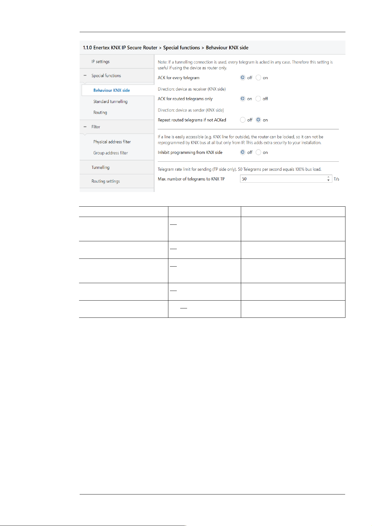
Figure 5: Behavior of the KNX side
Name Options Description
ACK for every telegram off/on The router acknowledges each
ACK for routed telegram only off/on The router only confirms the
Repeat routed telegrams if not
ACKed
Inhibit programming from TP
side
Max. number of telegrams to
KNX TP
Standard tunnel preferred IP
Enertex® devices offer the possibility for standard tunnel connections (before 2019) to assign
each of these tunnel connections to an IP address. In the analysis of group telegrams, this
makes it easier to assign the telegrams to the sender which "sits" behind the tunnel, as e.g.
Visualizations or smartphone apps.
Note:
This assignment can be resolved at any time by the ETS or a new so-called extended tunnel
connection (as of 2019).
telegram, even if it does not forward
this telegram (TP only)
telegrams that it forwards (TP only)
off/on The router repeats unconfirmed
individually addressed telegrams
(TP only)
off/on See parameter dialog
5 .. 50 See parameter dialog
Enertex® Bayern GmbH – Ebermannstädter Straße 8 - 91301 Forchheim - Deutschland - mail@enert ex.de
Page 10

1164-EnertexKNXIPSecureRouter_US-2.odt, 2019-03- 25 Seite 10 von 19
Figure 6: Preferred IP for Tunnelling
Name Options Description
Slow Connection off/on The tunnel connections over UDP
are controlled by default with a
connection timeout of 1 second.
This may be too short for
connections over the Internet.
UDP Connection Timeout 1 ,0 ... 8,0 sec Tunnel X should preferably be used
for communication with the
parametrized IP address.
Preferred IP for Tunnel X off/on
End device IP (IP-V4 Address)
Enertex® Bayern GmbH – Ebermannstädter Straße 8 - 91301 Forchheim - Deutschland - mail@enert ex.de
Page 11

Routing
1164-EnertexKNXIPSecureRouter_US-2.odt, 2019-03- 25 Seite 11 von 19
Figure 7: Routing
Name Options Description
Check of topology off/on See parameter dialog
Legacy routing off/on See parameter dialog
Physical address filter
Name Options Description
Physically addressed filter, block, route The physically addressed telegrams
Figure 8: Physical address filter
(e.g., actuator programming) may be
routed, blocked, or filtered via the
routing. This affects all
communication related to the device
address.
Block Broadcast Telegrams off/on Broadcast telegrams (e.g.,
Group address filter
searching for actuators in
programming state) can be routed or
blocked through the router.
Enertex® Bayern GmbH – Ebermannstädter Straße 8 - 91301 Forchheim - Deutschland - mail@enert ex.de
Page 12

Standard
1164-EnertexKNXIPSecureRouter_US-2.odt, 2019-03- 25 Seite 12 von 19
Figure 9: Standard Filter Group address
Name Options Description
IP=>KNX Direction: Telegrams from the IP
side to the KNX side
Main Group 0 to 13 filter, block, route Group
telegrams can be routed,
blocked or filtered via
the routing. Groups 14
Group telegrams can be routed,
blocked or filtered via the routing.
The groups 0 to 13 are summarized
here to a block.
and 15 are grouped
together to form a block.
Main Group 14 to 15 filter, block, route Group telegrams can be routed,
blocked or filtered via the routing.
Groups 14 and 15 are grouped
together to form a block.
Main Group 16 to 31 filter, block, route Group telegrams can be routed,
blocked or filtered via the routing.
The groups 16 and 31 are here
combined to form a block.
Extended Group Address
Filter
off/on In addition to the block-oriented
filtering of group address telegrams,
each group can also be separately
routed, blocked or filtered via the
routing. With this function, the
parameter dialog can be opened for
this purpose.
KNX=>IP Direction: Telegrams from the KNX
side to the IP side
Main Group 0 to 13 filter, block, route Group telegrams can be routed,
blocked or filtered via the routing.
The groups 0 to 13 are summarized
here to a block.
Enertex® Bayern GmbH – Ebermannstädter Straße 8 - 91301 Forchheim - Deutschland - mail@enert ex.de
Page 13

1164-EnertexKNXIPSecureRouter_US-2.odt, 2019-03- 25 Seite 13 von 19
Main Group 14 to 15 filter, block, route Group telegrams can be routed,
blocked or filtered via the routing.
Groups 14 and 15 are grouped
together to form a block.
Main Group 16 to 31 filter, block, route Group telegrams can be routed,
blocked or filtered via the routing.
The groups 16 and 31 are here
combined to form a block.
Extended Group Address
Filter
Extended Group Address Filter
For both directions, in addition to the block-oriented filtering of group address telegrams, each
group can also be individually routed, blocked or filtered via the routing. Therefore, there are the
links in the navigation bar when activated (see Figure 8 and Figure 9, respectively) „ext. filter
IP=>KNX“ and „ext. filter KNX=>IP“.
For each of these entries, there are 32 more group address filters that work independently of the
block-oriented filters. The settings of the 32 group address filters override those of the blockoriented filter.
off/on In addition to the block-oriented
filtering of group address telegrams,
each group can also be separately
routed, blocked or filtered via the
routing. With this function, the
parameter dialog can be opened for
this purpose.
Enertex® Bayern GmbH – Ebermannstädter Straße 8 - 91301 Forchheim - Deutschland - mail@enert ex.de
Page 14

1164-EnertexKNXIPSecureRouter_US-2.odt, 2019-03- 25 Seite 14 von 19
Figure 10: Extended Group Address Filter
Name Options Description
Main Group 00 inactive, filter, block,
forward
Group telegrams of this main group
can be routed, blocked or filtered via
the routing. If the filter is not active,
the behavior of the parameters of
Figure 8 and Figure 9, respectively.
Main Group NN
See above See above
NN= 1.. 31
Enertex® Bayern GmbH – Ebermannstädter Straße 8 - 91301 Forchheim - Deutschland - mail@enert ex.de
Page 15

Telnet
1164-EnertexKNXIPSecureRouter_US-2.odt, 2019-03- 25 Seite 15 von 19
Telnet can be used to request additional information from the IP router. Telnet access is factoryprotected with the password "knxsecure".
Once the router is in secure mode, the telnet interface is disabled.
Although it can be enabled for developer purposes prior to programming the secure mode, this is
a security risk.
help
ifconfig
ifconfig [help|dhcp|ip
|mask]
tpconfig
tpconfig [help|set]
lcconfig
systembc [0|1]
progmode [0|1]
apdu [55..248]
Displays all available commands
Displays network parameters
IP mode.......: DHCP
IP............: 192.168.33.142
Subnet mask...: 255.255.0.0
Gateway.......: 192.168.33.1
NTP server....: 192.53.103.108
Sys multicast.: 224.0.23.12
RT multicast..: 224.0.23.12
Hardware addr.: 00:50:c2:79:3f:ff
Sys multicast: Multicast address for System telegrams
RT multicast: Multicast address für routingt telegrams
Set network parameters via the telnet interface.
Expamples
Setting IP Addresse with DHCP:
ifconfig dhcp
Statically set the IP address to 192.168.1.2 (in this case, the gateway and mask should also be
adapted, see below)
ifconfig ip 192.168.1.2
Set the gateway to 192.168.1.1:
ifconfig gw 192.168.1.1
Set the mask to 255.255.255.0:
ifconfig mask 255.255.255.0
Show KNX parameters
KNX bus state.: up
KNX address...: 15.15.000
Serial number.: 00-a6-00-00-00-01
Set KNX parameters via the telnet interface.
Set the TP address to 1.1.0:
tpconfig set 1.1.0
Coupler type..: line coupler
IP -> KNX:
GA 0-13......: route
GA 14-15......: filter
GA 16-31......: block
Ph. addr......: filter
Broadcast.....: route
KNX -> IP:
GA 0-13......: route
GA 14-16......: filter
GA 16-31......: block
Ind.addr......: filter
Broadcast.....: route
Check IA rout.: disabled
Ind.Addr.tlg..: individually addressed telegrams are 3 times
repeated
Set certain bits in the system broadcasts so that IP routing is possible even on older devices
(e.g. Gira Homerserver). By default, this compatibility mode is turned on.
Wrong handling of bits in system broadcasts (necessary for e.g. Gira
Homeserver) is 1 (on)
Query or change programming mode (0 = off, 1 = on)
Read or configure the maximum length of the KNX TP telegrams. This may be necessary if
there is an incorrect implementation of a TP stack. In that case the ETS may try to use
telegrams with 248 bytes payload, but the TP device can not process (e.g. Zennio Z35i).
Default is 248 and should only be changed if necessary.
# apdu
maximal len of a KNX telegram 248.
Usage: apdu [55 .. 248]
Enertex® Bayern GmbH – Ebermannstädter Straße 8 - 91301 Forchheim - Deutschland - mail@enert ex.de
Page 16

1164-EnertexKNXIPSecureRouter_US-2.odt, 2019-03- 25 Seite 16 von 19
tpratemax [5..50]
stats
free [clear]
Read or configure maximum telegram rate (IP => TP); 50 T / s corresponds to 100% bus load.
# tpratemax
no limit, sending with maximum performance to TP.
Usage: tpratemax [5 .. 50]
Shows various statistics on device and bus status
uptime: 114 days, 2:19
KNX communication statistics:
TX to IP (all)..: 333729 (ca. 233 t/m)
TX to KNX.......: 23244 (ca. 16 t/m)
RX from KNX.....: 94559 (ca. 66 t/m)
Overflow to IP..: 0
Overflow to KNX.: 0
TX tunnel re-req: 260
TP bus voltage..: 28.95 V
TX TP rate......: 50 T/s (= 100 %)
Uptime: Runtime of the interface since last restart
TX to IP (all): Number of all telegrams sent on IP
TX to KNX: Number of all telegrams sent on KNX
RX from KNX: number of telegrams received from the KNX bus
Overflow to IP: Number of telegrams that could not be sent to IP
Overflow to KNX: Number of telegrams that could not be sent to the KNX bus
TX tunnel re-req: Number of telegrams that had to be repeated in the tunnel connections
TP bus voltage: Current bus voltage (at the time of calling stats)
TX TP rate: maximum telegram rate (TP)
Shows statistics about the memory usage
Used stack memory...: 14 %
Allocated memory....: 64 %
Unused memory.......: 35 %
TP-Tx buffer........: 0 %
TP-Tx buffer max....: 0 %
TP-Rx buffer max....: 0 %
Tunnel-T8 buffer max: 92 %
Used stack memory: Function stack utilization
Allocated memory: Allocated device memory
Unused memory: Unused device memory
TP-Tx buffer: Currently used TP send buffer
TP-Tx buffer max:Max. Utilization of TP send buffer (IP => TP) since system startup
TP-Rx buffer max:Max. Utilization TP receive buffer (IP <= TP) since system startup
Tunnel-XX (XX=1..8) buffer max:Max. Utilization of the tunneling buffer. Only tunnels whose
buffer was used at all will be displayed
Clear the buffer statistics:
free clear
Enertex® Bayern GmbH – Ebermannstädter Straße 8 - 91301 Forchheim - Deutschland - mail@enert ex.de
Page 17

1164-EnertexKNXIPSecureRouter_US-2.odt, 2019-03- 25 Seite 17 von 19
tunnel [1..8]
version
mask
display [0|1]
tunaddr 1..8 address
tunaddr reset
tunaddr setall
tunaddr help
tunmode [std/tpblk]
lock [0|1]
topology [0|1]
Tunneltime [1.0..8.0]
Shows active tunnel connections (without argument) or detailed information about the specified
tunnel connection (with argument 1..8)
# tunnel
Tunnels open: 1/8
1: 00.02.246, closed
2: 00.02.247, open (CCID: 82)
3: 00.02.248, closed
4: 00.02.249, closed
5: 00.02.250, closed
6: 00.02.251, closed
7: 00.02.252, closed
8: 00.02.253, closed
# tunnel 2
Tunnel 2..................: open (CCID 82)
KNX address...............: 00.02.247
HPAI control..............: 192.168.22.252:4808
HPAI data.................: 192.168.22.252:4808
Connect. type.............: TUNNEL_CONNECTION
Communication.............: UDP CONNECTION
TX tun req................: 23169
TX tun re-req.............: 0
RX tun req................: 821
RX tun re-req (identified): 0
RX tun req (wrong seq.)...: 0
Current tunnel buffer.....: 0 %
Connected since (UTC).....: 16:26:16 29-01-2019
CCID: Connection ID of the tunnel connection
KNX address: Tunnelling address
HPAI control: Control endpoint of the connection partner
HPAI data: Data endpoint of the connection partner
Connect. Type:Connection type tunnel or management connection
Communication: UDP or TCP Connection
TX tun req: Number of telegrams sent to the tunnel connection
TX tun re-req: Number of telegrams that had to be repeated in the tunnel connections
RX tun req: Number of telegrams received from the tunnel connections
RX tun re-req: Number of telegrams received twice by the tunnel connections
RX tun req (wrong seq.):number of frames received from the tunnel connections with wrong
sequence number
Current tunnel buffer: Utilization currently of the IP buffer of the tunnel
Connected since (UTC): Time since the tunnel connection has been established.
Firmware-Version
Mask-Version
Query or change the display mode (0 = standard, 1 = inverted)
KNX address of a tunnel read (tunaddr) or change, e.g. tunaddr 1 15.15.240, set all
tunnel addresses consecutively from a certain start address (tunaddr setall 15.15.15),
or reset the KNX addresses of all tunnels to factory settings (tunaddr reset)
# tunaddr
1: KNX address: 15.15.010
2: KNX address: 15.15.011
3: KNX address: 15.15.012
4: KNX address: 15.15.013
5: KNX address: 15.15.014
6: KNX address: 15.15.015
7: KNX address: 15.15.016
8: KNX address: 15.15.017
Read tunnel mode (without parameters) or set (tp or tpblk);
tunmode tpblock:IP => KNX If same backbone forward to line frame
KNX=> IP if same sub line send to backbone
Query lock status (without further parameters) or change (0 = off, 1 = on). Setting is identical to
programming lock TP page, Figure 5.
A router can prevent the forwarding of physically addressed telegrams by filtering, i. It is not
possible to reprogram devices across a line. This becomes interesting when using outdoor
lines.
However, e.g. if a KNX-USB interface is connected to an outdoor line directly to the bus, the
router itself could be re-programmed, so that it forwards the physically addressed telegrams.
With that, any access to the internal line is possible.
This can be prevented with this telnet function. If you set telnet "lock" to 1, the router can no
longer be programmed via the KNX line and corresponding activation of forwarding via KNX
TP is no longer possible.
Query or change "topology check" (0 = off, 1 = on). Setting is identical to "Topology check",
Figure 7
Subline Topology has been violated with 1.2.3
Last logged at 18:28:31 09-11-2018
Mainline Topology has been violated with 1.2.3
Last logged at 18:24:31 09-11-2018
Query or change timeout for tunnel connection (1.0 to 8.0). Setting is identical to "slow
connection", Figure 6
Enertex® Bayern GmbH – Ebermannstädter Straße 8 - 91301 Forchheim - Deutschland - mail@enert ex.de
Page 18

1164-EnertexKNXIPSecureRouter_US-2.odt, 2019-03- 25 Seite 18 von 19
tunudp
date
sntp [query|server IP]
sendack [0|1]
blockfilter [0|1]
routingcounter [0|1]
logmem
passwd oldpw newpw
passwd oldpw
passwd newpw
secure [0|1]
factory_reset
die
reboot
logout
Query or change the type of tunnel connection for the ETS (0 = default, 1 = UDP only).
Show date and time
Send request to the NTP server (sntp query) or set the IP of the NTP server (sntp
server 1.2.3.4)
Querying or changing every telegram (ACK). Setting is identical to the documentation to
Figure 5.
Disable all group address filters (i.e., forward all) regardless of the settings of the ETS. Query
or change (0 = off, 1 = on).
Query or change routing counter handling (0 = default, 1 = behavior before 2018). This setting
is identical to Legacy Routing Algorithm <2018, Figure 7
Event memory in the device. Suitable for the development of clients. Read out for support
requests.
Changes the current Telnet password (passwd), deletes the current password (old passwd) or
sets a new password if none is currently set (new passwd)
Display or change the behavior of the Telnet interface in secure mode (0 = disable, default, 1 =
enable)
Note: Although it can be enabled for developer purposes prior to programming the
secure mode, this is a security risk.
Reset to factory settings and reboot
Test hardware watchdog. Executes reset.
reboot
end Telnet-Session
Latest documentation and
Software
Under http://www.enertex.de/d-produkt.html you will find the current ETS database file as well as
the current product description.
Specification
Symbols
KNX (Powersupply) DC 21 ... 32 V SELV
Ethernet-Interface Rj45-connector 10M/100MBit Ethernet
Display Graphical OLED, 128x64
KNX Functions • KNXIP Secure Tunneling and Routing
Environment -5 ... +45° C
Installation • Only for use in dry interiors.
Outer dimensions 35,0 mm x 89,6 mm x 62,9 mm (L x B x H)
Must not be disposed of with household waste.
current consuimption < 20 mA
Programming LED (red), Bus Activity LED (yellow), Voltage LED (green flashing)
Network link (green), network activity (yellow)
• Up to 48 telegrams per second
• AES 128 encryption
• Asymmetric key exchange for tunnel connections
• UDP and TCP communication
• Up to 8 tunnel connections
• Up to 62 group address filters
• APDU 248, parameterizable between 55 and 248
• TP telegram rate limit
• TP bus voltage measurement (display telnet or display)
• Only for installation in distributor according to DIN 43880 on DIN rail
35mm according to EN 50022.
• Degree of protection IP20
Enertex® Bayern GmbH – Ebermannstädter Straße 8 - 91301 Forchheim - Deutschland - mail@enert ex.de
Page 19

Open Source Software
This product uses third-party software from the following authors:
Adam Dunkels <adam@sics.se>
Marc Boucher <marc@mbsi.ca> and David Haas <dhaas@alum.rpi.edu>
Guy Lancaster <lancasterg@acm.org>, Global Election Systems Inc.
Martin Husemann <martin@NetBSD.org>.
Van Jacobson (van@helios.ee.lbl.gov)
Paul Mackerras, paulus@cs.anu.edu.au,
Christiaan Simons <christiaan.simons@axon.tv>
Jani Monoses <jani@iv.ro>
Leon Woestenberg <leon.woestenberg@gmx.net>
LWIP
Quelle: https://savannah.nongnu.org/projects/lwip/
Copyright (c) 2001-2004 Swedish Institute of Computer Science.
All rights reserved.
Redistribution and use in source and binary forms, with or without modification,
are permitted provided that the following conditions are met:
1. Redistributions of source code must retain the above copyright notice,
this list of conditions and the following disclaimer.
2. Redistributions in binary form must reproduce the above copyright notice,
this list of conditions and the following disclaimer in the documentation
and/or other materials provided with the distribution.
3. The name of the author may not be used to endorse or promote products
derived from this software without specific prior written permission.
THIS SOFTWARE IS PROVIDED BY THE AUTHOR ``AS IS AND ANY EXPRESS OR IMPLIED
WARRANTIES, INCLUDING, BUT NOT LIMITED TO, THE IMPLIED WARRANTIES OF
MERCHANTABILITY AND FITNESS FOR A PARTICULAR PURPOSE ARE DISCLAIMED. IN NO EVENT
SHALL THE AUTHOR BE LIABLE FOR ANY DIRECT, INDIRECT, INCIDENTAL, SPECIAL,
EXEMPLARY, OR CONSEQUENTIAL DAMAGES (INCLUDING, BUT NOT LIMITED TO, PROCUREMENT
OF SUBSTITUTE GOODS OR SERVICES; LOSS OF USE, DATA, OR PROFITS; OR BUSINESS
INTERRUPTION) HOWEVER CAUSED AND ON ANY THEORY OF LIABILITY, WHETHER IN
CONTRACT, STRICT LIABILITY, OR TORT (INCLUDING NEGLIGENCE OR OTHERWISE) ARISING
IN ANY WAY OUT OF THE USE OF THIS SOFTWARE, EVEN IF ADVISED OF THE POSSIBILITY
OF SUCH DAMAGE.
1164-EnertexKNXIPSecureRouter_US-2.odt, 2019-03- 25 Seite 19 von 19
Enertex® Bayern GmbH – Ebermannstädter Straße 8 - 91301 Forchheim - Deutschland - mail@enert ex.de
 Loading...