

EnerSys SBS30, SBS15, SBS60, SBS40, SBS110 Series Manual
...
Publication No: EN-SBS-PG-001 February 2003

Introduction 2
Range Summary 3
Recombination Technology 4
Construction 5
Features and Benefits 6
Battery Sizing 7-8
Performance Data 9-14
Performance Information 15-16
Installation 17
Housings 18
Charging 19-21
Maintenance 22
Introduction
2
Contents
PowerSafe SBS standby power batteries
utilise advanced pure lead, thin plate
technology to achieve exceptionally high
performance, energy density, reliability
and a long, low maintenance service life
in a wide range of applications and
operating environments. The range
includes both top and front terminal
designs for easy installation and
maintenance on racks, shelves and in
cabinets.
PowerSafe SBS combine the benefits of
high performance and long life in a
cost effective battery solution for
tele-communications, UPS, electric
utillities and engine starting
applications.
PowerSafe SBS batteries are
manufactured in ISO 9001 certified
factories.
This manual describes the
PowerSafe SBS product range, physical
characteristics and electrical
performance, and contains the basic
information for the selection, storage,
installation, operation and maintenance
of
PowerSafe SBS batteries.
Enersys has earned an international
reputation for quality and reliability
based on more than 100 years
experience in the manufacture of
batteries, and is at the forefront of new
product design to meet customers
increasing power requirements.
PowerSafe SBS batteries are designed
using proven gas recombination
technology, which removes the need
for regular water addition.
The use of gas recombination
technology for lead acid batteries has
completely changed the concept of
standby power. This technology
provides the user with the freedom to
use lead acid batteries in a wide range
of applications. The minimal level of gas
production allows battery installation in
cabinets or on stands, in offices or near
main equipment, thus maximising space
utilisation and reducing battery
accommodation and maintenance costs.
Publication No: EN-SBS-PG-001 February 2003
www.enersysinc.com

3
Range Summary
Dimensions mm (inches)
Nominal C8 to C10 to
Voltage 1.75Vpc 1.80Vpc Terminal Weight
Model (V) @ 25°C (77°F) @ 20°C (68°F) Fastener
1
Length Width Height kg (lbs)
SBS8 12 7 7 M4 F 138 (5.4) 86 (3.4) 101 (4.0) 2.7 (5.9)
SBS15 12 14 14 M6 M 200 (7.9) 77 (3.0) 140 (5.5) 5.7 (12.5)
SBS30 12 26 26 M6 M 250 (9.8) 97 (3.8) 156 (6.1) 9.5 (20.9)
HB30 12 26 26 M6 M
2
250 (9.8) 97 (3.8) 156 (6.1) 9.6 (21.1)
SBS40 12 38 38 M6 M 250 (9.8) 97 (3.8) 206 (8.1) 12.7 (28.0)
SBS60 12 51 51 M6 M 220 (8.7) 121 (4.8) 260 (10.2) 18.5 (40.7)
SBS110 6 116 115 M8 M 200 (7.9) 208 (8.2) 239 (9.4)
3
21.2 (46.6)
SBS114 4 116 115 M8 M 200 (7.9) 208 (8.2) 239 (9.4)
3
15.7 (34.5)
SBS130 6 133 132 M8 M 200 (7.9) 208 (8.2) 239 (9.4)
3
22.7 (49.9)
SBS134 4 133 132 M8 M 200 (7.9) 208 (8.2) 239 (9.4)
3
26.8 (37.0)
SBS300 2 307 310 M8 M 200 (7.9) 208 (8.2) 239 (9.4)
3
21.7 (47.7)
SBS390 2 361 360 M8 M 200 (7.9) 208 (8.2) 239 (9.4)
3
23.2 (51.0)
SBSJ13 12 12 12 M6 F 178 (7.0) 87 (3.4) 132 (5.2) 5.7 (12.6)
SBSJ16 12 15 15 M6 F 186 (7.3) 79 (3.1) 171 (6.7) 6.7 (14.8)
SBSJ30 12 26 26 M6 F 178 (7.0) 168 (6.6) 127 (5.0) 11.8 (26.0)
SBSJ40 12 39 39 M6 F 201 (7.9) 171 (6.7) 173 (6.8) 17.4 (38.2)
SBSJ70 12 64 64 M6 F 328 (12.9) 166 (6.5) 175 (6.9) 28.8 (63.4)
SBSB8
4
12 31 31 M8 F 280 (11.0) 97 (3.8) 150 (5.9)
5
10.3 (22.7)
SBSB10
4
12 34 34 M8 F 280 (11.0) 97 (3.8) 175 (6.9)
5
12.8 (28.2)
SBSB14
4
12 62 62 M8 F 280 (11.0) 97 (3.8) 256 (10.1)
5
19.1 (42.0)
SBSC11
4
12 91 92 M8 F 395 (15.6) 105 (4.1) 264 (10.4) 28.0 (61.6)
Monobloc Specifications
Notes:
1 M = male stud, F = female thread
2 supplied with wiring harness
3 dimension includes top cover
4 SBSB8, B10, B14, and C11 are available with terminals on the top face or on the front face.
For front terminals add ‘FT Adapter’ to the model number
5 SBSB8, B10 and B14 are available with a venting manifold, with a spigot at the front or back.
The manifold increases monobloc height by 9mm.
Publication No: EN-SBS-PG-001 February 2003
www.enersysinc.com
4
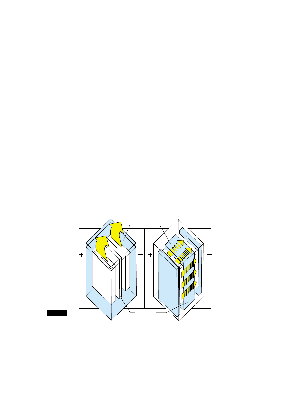
Recombination Technology
How gas recombination works
When a charge current flows through a fully charged conventional
lead acid cell, electrolysis of water occurs to produce hydrogen from
the negative electrode and oxygen from the positive electrode. This
means that water is lost from the cell and regular topping up is
needed.
However, evolution of oxygen gas and hydrogen gas does not occur
simultaneously, because the efficiency of recharge of the positive
electrode is not as good as the negative electrode. This means that
oxygen is evolved from the positive plate before hydrogen is
evolved from the negative plate.
At the same time that oxygen is evolved from the positive electrode,
a substantial amount of highly active spongy lead exists on the
negative electrode before it commences hydrogen evolution.
Therefore, provided oxygen can be transported to the negative
electrode, conditions are ideal for a rapid reaction between lead and
oxygen:
ie. This oxygen is electrochemically reduced on the negative
electrode according to the following scheme,
2e-+ 2H+ +
1/
2
O
2
➝ H
2
O
and the final product is water.
The current flowing through the negative electrode drives this
reaction instead of hydrogen generation which would occur in a
flooded cell.
This process is called gas recombination. If this process was 100%
efficient no water would be lost from the cell. By careful design of
the constituents within the cell, gas recombination up to 99% is
achieved.
Principle of the Oxygen Reduction Cycle
Electrolyte
Separator
H
2
O
2
SBS
Oxygen evolved
from positive
plate transfers
to negative and
recombines to
form water.
CONVENTIONAL
CELL
Oxygen and
hydrogen escape
to the
atmosphere
Recombination efficiency
Recombination efficiency is determined under specific conditions by
measuring the volume of hydrogen emitted from the battery and
converting this into its ampere hour equivalent. This equivalent
value is then subtracted from the total ampere hours taken by the
battery during the test period, and the remainder is the battery’s
recombination efficiency and is usually expressed as a percentage.
As recombination is never 100%, some hydrogen gas is emitted from
SBS cells and batteries through the self-regulating valve. The volume
of gas emitted is very small and for all practical purposes may
be ignored.
Figure 1
Publication No: EN-SBS-PG-001 February 2003
www.enersysinc.com
5
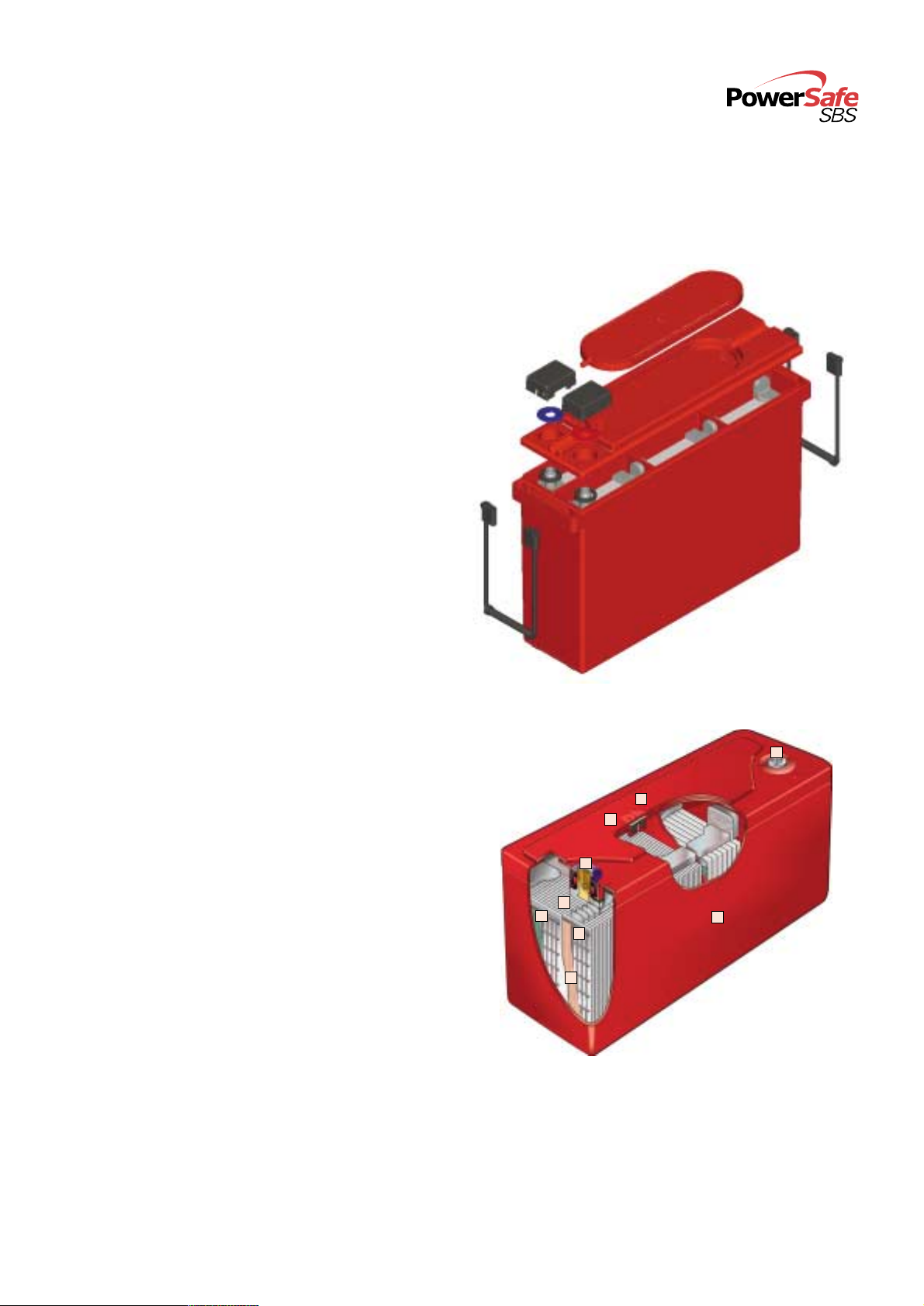
Construction
1 Terminal Posts
High conductivity post for high rate discharge.
2 Pillar Seal
Compressed rubber grommet for superior integrity.
3 Container and Lid
Heat-sealed for maximum strength. SBS cases are
made of ABS and SBS J are made of Noryl.
Both materials are flame retardant (UL94 V-0).
4 One Way Valve
Ensures no oxygen can enter the cell. Optional
remote venting systems are available. Vent adapters
and a neoprene tubing system transport gases
outside the battery compartment. This is only a
safety measure because, under normal operating
conditions, gas emission is virtually negligible.
5 Pure Lead Plates
Advanced thin grid technology and high purity
materials for high performance, efficient charging
and long life.
6 Negative Plates
Active material is balanced against the positive for
optimum performance and recombination
efficiency.
7 Flame Arrestor
The valve retaining disc also functions as a flame
Arrestor to prevent ingress of a spark or flame.
8 Separators
Separator material is resilient to scuffs and tears
to minimise risk of internal shorts caused by a
damaged separator.
9 Electrolyte
Medical grade dilute sulphuric acid is absorbed
into separator material.
2
7
8
5
9
4
1
3
6
Publication No: EN-SBS-PG-001 February 2003
www.enersysinc.com
6
Features and Benefits
Design Life
■ High purity materials give SBS batteries a long float life.
On constant voltage float charge systems the design life
expectancy is 10+ years at 25°C/77°F and 15+ years at
20°C/68°F.
Energy Density
■ The advanced thin plate pure lead technology promotes
exceptionally efficient utilisation of the active materials.
SBS energy density is typically 12 to 30 % higher than
conventional lead calcium VRLA batteries.
Operating Temperature
■ The recommended operating temperature range for
optimum life and performance is 20°C/68°F to 25°C/77°F.
■ However, SBS can be operated in the temperature range
-40°C/-40°F to 50°C/122°F, and by using the optional
metal jacket the maximum operating temperature of the
SBS J types is increased to 80°C/176°F.
■ Operation at higher or lower temperature will effect
battery life or performance respectively:
Lower capacity Optimum life Shorter life
and performance
Transportation
■ SBS products are classified as “nonspillable wet electric
storage batteries” and may be shipped by air or ground
transportation without restriction.
■ The batteries, their shipping container and external
packaging must be labelled “nonspillable” or “nonspillable
battery”.
■ SBS batteries are in compliance with:
USA 49 Code of Federal Regulations section DOT 173.159
ICAO/IATA Packaging Instruction 806 and Special
Provision A67
IMDG UN No 2800 Class 8 Exempt when securely
packaged and protected against short circuts.
Orientation
The batteries can be installed in any orientation except
upside down (vents on the bottom).
Terminal Position
■ The SBS range comprises of both top and front terminal
models, and JIS and unique SBS container sizes for
maximum battery layout flexibility.
Low Gas Emission and Remote venting
■ Under normal operating conditions, gas emission is
virtually negligible. On SBS15-60, SBS J and front terminal
models optional venting systems are available to vent gas
outside the battery compartment. The remote venting
system allows batteries to be installed in applications
where there is little ventilation.
-40°C/-40°F to 20°C/68°F to 26°C/78°F to
19°C/66°F 25°C/77°F 50°C/122°F
Publication No: EN-SBS-PG-001 February 2003
www.enersysinc.com
7
Battery capacity is affected by the discharge rate, end
voltage, temperature and age.
Battery sizing calculations should include factors for
temperature and loss of capacity over life. A battery usually
is determined to have reached end of life when its capacity
has fallen to 80% of its rated capacity.
Strings of the same SBS batteries can be connected in
parallel to obtain higher capacities.
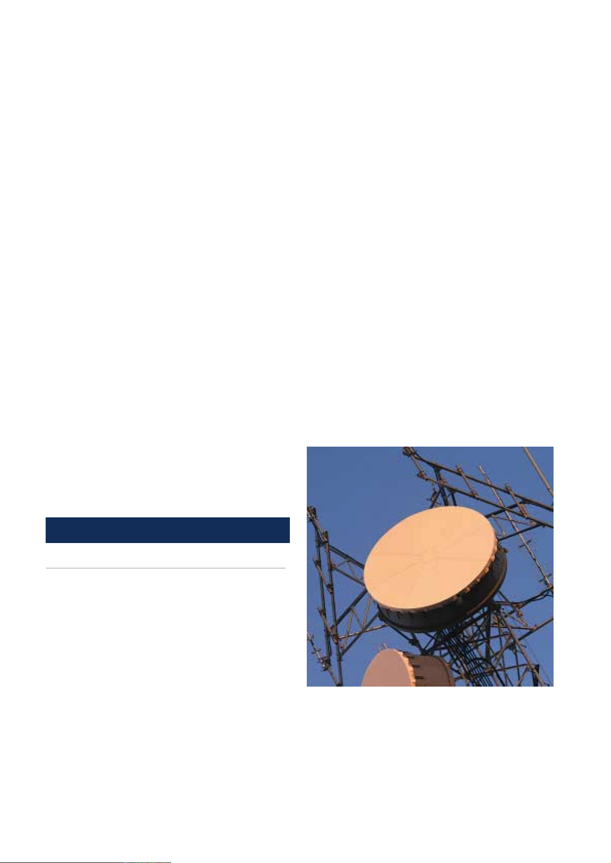
Telecom Applications
In general, telecom applications are a constant power or
constant current load for a specified period, to a specified
end voltage. The appropriate battery model can be selected
by referring to the Discharge Tables.
EXAMPLE 1
The following information is needed:
■ Nominal system voltage
■ Minimum system voltage
■ Load (constant current or constant power)
■ Backup time
■ Temperature range
A nominal 48V system requires a constant current of 9 Amps
for 4 hours to a minimum of 42V at a minimum operating
temperature of 20°C/68°F.
Step 1. Number of cells = nominal system voltage divided
by nominal cell voltage:
48V/ 2V = 24 cells
Step 2. Cell end voltage = minimum system voltage divided
by the number of cells:
42V/ 24 cells = 1.75 volts per cell
Step 3. Correct load for temperature and ageing:
Temperature factor = 1/Factor from Temperature
Correction Chart = 1/0.978 = 1.022
Ageing factor = 100/80 = 1.25
9 amps x temperature factor x ageing factor =
9 amps x 1.022 x 1.25 = 11.5 Amps
Step 4. Refer to the constant current discharge table for an
end voltage of 1.75 Vpc, and in the 4 hour column
find the model that will provide the load current.
In this example an SBS60 will provide 11.7 amps/
4 Hrs/1.75Vpc SBS60 is a 12V six cell monobloc,
so 4 blocs are required for a 48V battery.
UPS Applications
In general, UPS systems are rated in kVA, (kilo Volt
Amperes). This is a multiplication of the output voltage in
Kilo Volts and output current in amperes. The kVA rating is
always an AC rating. The kVA rating may be converted to kW
by simply multiplying the kVA by the Power Factor (PF).
kW Rating of UPS = (kVA of UPS) x (PF of UPS)
kW Rating of UPS Battery = kVA x PF
Inverter Efficiency
EXAMPLE 2
This first example covers a basic sizing procedure with no
power factor or efficiency involvement. This procedure
details only the fundamental steps required.
In an example such as this the following information is
needed as a minimum requirement:
(i) system kilowatts
(ii) required autonomy (run time)
(iii) minimum DC voltage
(iv) maximum DC voltage
If the load is given in kVA, then the PF and inverter efficiency
values must also be known.
Therefore, for a UPS requiring the following autonomy,
Battery kW Rating: 10
Battery nominal voltage: 120
Battery end voltage: 1.67 Vpc
Battery run time: 10 minutes
Battery Sizing
Publication No: EN-SBS-PG-001 February 2003
www.enersysinc.com

8
Step 1. Number of cells needed per string
= 120 (nom.volt) /2 (nominal cell voltage)
= 60 cells
Step 2. Watts per cell required to support the load
= 10,000 (Watts) /60 (cells)
= 166.67 Watts per cell
Step 3. Refer to the constant power discharge tables for an
end voltage of 1.67 Vpc, and in the 10 minute
column find the model that can support a load of
166.67 Watts per cell.
SBS40 will provide 205 Wpc for 10 minutes.
Step 4. Calculate the number of blocs required to make up
the battery string. The number of blocs
= System Nominal Voltage/Bloc Nominal Voltage
= 120V/12V = 10 blocs.
Therefore 10 SBS40 blocs are required to make up
the battery string
EXAMPLE 3
This example is slightly more complex in that it takes into
account both the power factor and the system efficiency.
UPS kVA rating: 12.0
Inverter power factor: 0.80
Inverter efficiency: 85%
Battery nominal voltage: 120
Battery end-voltage: 1.67 Vpc
Battery run time:15 minutes
Step 1. Total power required from
battery = kVA x PF
Inverter Efficiency
= 12.000(kVA)x0.80(PF)
0.85 (Inv.eff)
= 11.294 kW
Step 2. Watts per cell required to support the load
= Total power required from battery
no. of cells
= 11.294 (kW)
60 (cells)
= 188.2 Watts per cell
Step 3. Refer to the constant power discharge tables for an
end voltage of 1.67 Vpc, and in the 15 minute
column find the model that can support a load of
188.2 Watts per cell.
SBS60 will provide 206 Wpc for 15 minutes.
Step 4. Calculate the number of blocs required to make up
the battery string. The number of blocs
= System Nominal Voltage/Bloc Nominal Voltage
= 120V/12V = 10 blocs.
Therefore 10 SBS60 blocs are required to make up
the battery string
With both of these examples, by reference to the discharge
tables, it is possible to use a parallel string system with
smaller SBS models.
These are basic examples. For split duty regimes and other
more complex sizings, contact our sales department.
Battery Sizing
Publication No: EN-SBS-PG-001 February 2003
www.enersysinc.com
 Loading...