

Page 1
Installation, Operations
and Maintenance
Instructions
Publication No: EN-VX-IOM-001 February 03
Page 2
2
Important information 2
Care for your safety 2
Unpacking 2
Storage 3
Installation 3
Cell strings connected in
parallel 3
Charging 4
Discharging 4
Technical specifications of bloc 6
Typical assembly drawing 6
Battery record sheet 7
Important information
Please read this manual immediately on
receipt of the battery before commencing
unpacking and installing. Failure to comply
with these instructions will render any
warranties null and void.
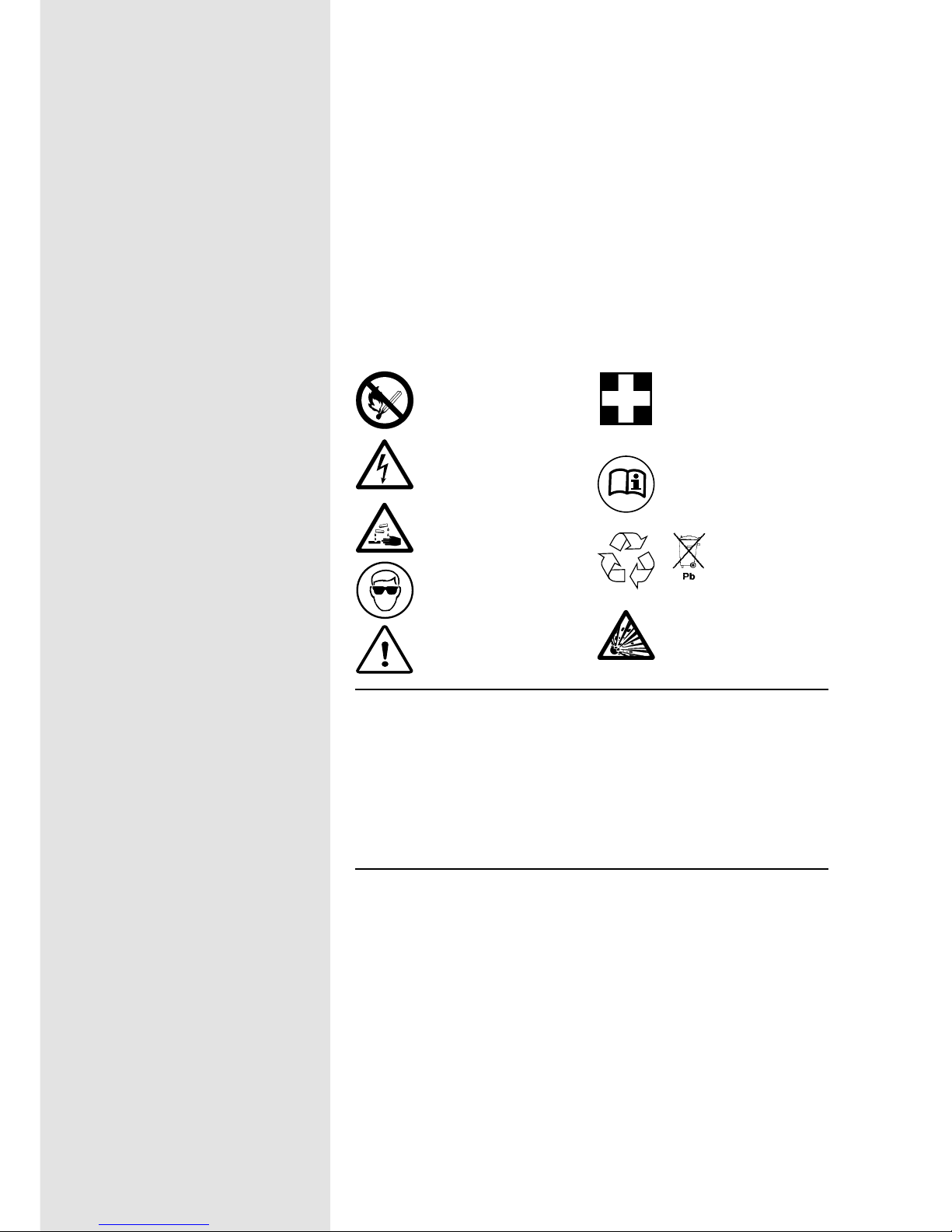
Care for your safety
No smoking, no naked flames,
no sparks
Electrolyte is corrosive
Electrical hazard
Shield eyes
Clean all acid splash in eyes or
on skin with plenty of clean
water. Then seek medical help.
Acid on clothing is to be
washed with water.
Danger
Read instructions
Risk of explosion or fire. Avoid
any short circuit. Metallic parts
under voltage on the battery, do
not place tools or items on top of
the battery.
Re-cycle scrap
batteries.
Contains lead
Unpacking
It is advisable to unpack the monoblocs
and accessories before commencing
assembly and erection and not to unpack
and erect monobloc by monobloc.
All monobloc/units should be handled
carefully as the plastic container can be
damaged or broken if dropped. Under no
circumstances should the batteries be
lifted by their terminal pillars.
All items should be carefully checked
against the accompanying advice notes to
ascertain if any are missing or damaged.
In this event contact your Enersys
representative.
Handling
PowerSafe VX batteries are
supplied in a fully charged
state and must be unpacked
carefully to avoid very high
short-circuit currents between
terminals of opposite polarity.
Keep flames away
In case of accidental
overcharge a flammable gas
may be emitted from the
safety vent.
Discharge any possible static
electricity from clothes by
touching an earth connected
part.
Tools
Use tools with insulated
handles.
Do not place or drop metal
objects on the battery.
Remove rings, wristwatch and
articles of clothing with metal
parts that may come into
contact with the battery
terminals.
Publication No: EN-VX-IOM-001 February 03
www.enersysinc.com
Page 3

3
A rigid plastic insulating cover is provided which protects the unit
terminals. These are factory fitted and there is no need to remove
them until access to the terminals is required.
Storage
Store the batteries in a dry, clean and preferably cool location.
As the batteries are supplied charged it is advised not to store
batteries without a refreshing charge for more than:
6 months at 20°C
3 months at 30°C
6 weeks at 40°C
3 weeks at 50°C
The refreshing charge needs to be at 2.27-2.30Vpc at 20°C for 48 to
96 hours. A current limit is not essential, but for optimum charge
efficiency the current output of the charger can be limited to 10%
of the 3 hour capacity rating. The need for a refreshing charge
can also be determined by measuring the open circuit voltage of
the stored battery. Refreshing charge is advised if the voltage
drops below 2.10Vpc. Failure to observe these conditions may
result in greatly reduced capacity and service life.
Temperature
Avoid placing the battery in a hot environment or in front of a
window. The battery will give the best performance and service
life when working at a temperature between 20°C and 25°C.
Operating temperatures should not exceed +45°C or fall below 30°C.
Ventilation
Under normal conditions gas release is very low and natural
ventilation is sufficient for cooling purposes and inadvertent
overcharge, enabling PowerSafe VX batteries to be used safely in
offices and with main equipment.
However care must be taken to ensure adequate ventilation when
placed in cabinets. Batteries must not be placed in sealed
cabinets.
Installation
Install batteries in a clean and dry area. PowerSafe VX products
release minimal amounts of gas during normal operation (gas
recombination efficiency ≥ 95%). Batteries must be installed in
accordance with national standards
(for instance EN 50272-2), otherwise in accordance with the
manufacturer’s instructions.
Please note that each monobloc is supplied complete with a
fastener set, i.e. nut, spring washer and plain washer. These are
fitted to the threaded stud of each terminal pillar prior to despatch
from the factory.
Enersys battery racks or cabinets are recommended when
installing the monoblocs. Assemble the rack according to
instructions. Place the battery blocs on the rack at their correct
cell centres (as indicated on the connection drawing) and arrange
the positive and the negative terminals for connection according
to the wiring diagram.
Connection of monoblocs
When all monoblocs have been placed on the stands/in the
cabinets, connect them together by means of the connecting straps
and fastener set, in sequence, pillar, connecting strap, plain washer,
spring washer and nut.
Tighten the fastener set nut(s) to a level of fastening torque of 5 ±0.5
Nm. Never use a standard spanner, use insulated tools only.
A loose connector can cause problems in charger adjustment,
erratic battery performance, possible damage to the battery
and/or personal injury.
Single solid sleeved copper strap connector type SUB5176 is used to
connect units located on the same tier of the stand (or on the same
shelf of a cabinet). A single flexible insulated cable connector is
used for inter-tier (or inter-shelf) connection which is provided when
the stand is supplied by Enersys.
Putting the terminal cover back
Insulating terminal covers have been designed to be fitted on
completion of the connecting up sequence of the battery. Where
inter-tier flexible insulated cable connectors are used, it will be
necessary to remove the corner of the cover by simply snapping it
off.
Publication No: EN-VX-IOM-001 February 03
www.enersysinc.com
Page 4

4
Cell strings connected in parallel
Using constant voltage chargers and ensuring that the
connections made between the charger and the batteries have
the same electrical resistance, no special arrangements have to
be made for batteries in parallel.
Although no special circuit arrangements are required, where the
parallel connection is made at the charger or distribution board, to
avoid out of step conditions, the bus bar run length and the area of
cross section should be designed so that the circuit resistance
value for each of the strings is equal within limits ± 5%.
Charging
Float voltage
The recommended float charge voltage is 2.28 volts per cell at
20°C.
Following a commission charge and after 6 months continuous
charge at the recommended float voltage, individual cell voltages
will stabilise within ±4.5% of the mean applied voltage.
However, immediately following commissioning and for the initial 6
months of continuous float charge, individual cell voltage values
outside the above tolerance may be observed without adverse
effect. There is no relationship between a cell’s float voltage and
its discharge capacity. Cells are perfectly capable of giving their
discharge capacity even when outside the ±4.5% range.
After 6 months service, should any individual cell or monobloc
show a continuing reduction or increase in voltage outside the
above limits over 3 successive monthly periods, Enersys should be
contacted for advice.
When the average ambient temperature deviates more than ±5ºC
from the reference temperature (20°C), it is necessary to adjust
the float voltage as follows:
Temperature Float voltage range per cell
0°C 2.33-2.36V
10°C 2.30-2.33V
20°C 2.27-2.30V
25°C 2.25-2.28V
30°C 2.24-2.27V
35°C 2.22-2.25V
40°C 2.21-2.24V
45°C 2.19-2.22V
50°C 2.18-2.21V
If the charger does not permit an adjustment of float voltage in
relation to the temperature, it is possible to set a float voltage
value according to the temperature ranges as indicated in the last
table of this publication.
Charging current
A discharged VRLA battery will accept a high recharge current,
but for those seeking a more economical charging system a
current limit of 0.08 C10 or 0.1 C3 (A) is adequate.
Fast recharge
Increasing the charge voltage to 2.40Vpc with a current limited to
0.1 C
10 or 0.125 C3 (A) can reduce recharge times. Fast charge
should be stopped after approximately 10 to 15 hours. In order to
achieve a normal service life, this charge regime must not be used
more than once per month.
Float charge ripple
Excessive ripple on the D.C. supply across a battery has the effect
of reducing life and performance.
It is therefore recommended that voltage regulation across the
system, including the load but without the battery connected,
under steady state conditions, shall be better than ±1% between
5% and 100% load.
State of charge
The battery state of charge can be determined approximately by
measuring the open circuit voltage after the battery has been at
rest for a minimum of 24 hours at 20°C.
Voltage State of charge
2.14Vpc 100%
2.10Vpc 80%
2.07Vpc 60%
2.04Vpc 40%
2.00Vpc 20%
Open circuit voltage variation with temperature is 2.5mV per 10°C.
Discharging
PowerSafe VX batteries must not be left in a discharged condition
after supplying the load but must immediately be returned to float
recharge mode.
Failure to observe these conditions may result in greatly reduced
service life.
Publication No: EN-VX-IOM-001 February 03
www.enersysinc.com
Page 5

5
Accidental deep discharging
For optimum operation the minimum voltage of the system should
be related to the duty as follows:
Duty Minimum end voltage
5 min ≤ t ≤ 1h 1.65V
1h ≤ t ≤ 5h 1.70V
5h ≤ t ≤ 8h 1.75V
8h ≤ t ≤ 20h 1.80V
In order to protect the battery it is advisable to have system
monitoring and low voltage cut-out.
Deep discharge will produce a premature deterioration of the
battery and a noticeable reduction in the life expectancy of the
battery.
The effect of temperature
- on capacity
Correction factors for capacity, according to the temperature, are
as follows:
- on life
Operation of valve regulated batteries at temperatures higher than
20°C will reduce life expectancy. Life is reduced by 50% for every
10°C rise in temperature.
Maintenance/Checks
PowerSafe VX are maintenance free, sealed, lead acid batteries
and need no water addition.
The containers and lids shall be kept dry and free from dust.
Cleaning must be carried out with a damp cotton cloth only. Check
monthly that total voltage at battery terminals is (N x 2.28 V) for a
temperature at 20°C. (N = the number of cells in the battery). Take
annual readings of the voltages of cells making up the battery.
Keep a logbook to record values, power outages, discharge tests,
etc.
An autonomy test is recommended once a year.
Technical data when charging with a constant voltage
If the charger does not permit an adjustment of the float voltage in
relation to the temperature, it is possible to set a float voltage
value and a recharging voltage value according to the
temperature ranges indicated in the table below:
Temperature Float Voltage Recharging Voltage
0°C to 10°C 2.34Vpc 2.45Vpc
10°C to 20°C 2.31Vpc 2.40Vpc
20°C to 30°C 2.28Vpc 2.35Vpc
30°C to 40°C 2.25Vpc 2.30Vpc
40°C to 50°C 2.22Vpc 2.25Vpc
Discharge 0°C 5°C 10°C 15°C 20°C 25°C 30°C 35°C 40°C 45°C 50°C
Time
5 mins to 0.80 0.86 0.91 0.96 1 1.04 1.06 1.09 1.1 1.12 1.13
59 mins
1h to 24h 0.86 0.90 0.94 0.97 1 1.03 1.05 1.06 1.07 1.08 1.09
Publication No: EN-VX-IOM-001 February 03
www.enersysinc.com
Page 6

6
3
2
1
4
Type Length Width Height Cell Weight
Centres (kg)
8VX100F 384 125 228 135 32
12VX100F 384 125 228 135 48
Technical specifications of bloc
All dimensions in millimetres
Item No. Description Cat No.
1 Fastener set M6 2 Inter-unit connector SUB5176
3 Inter-tier connector (35 mm
2
max.) -
4 Insulating terminal cover SPH0571B
Typical connection assembly
Typical assembly drawing
Publication No: EN-VX-IOM-001 February 03
www.enersysinc.com
Page 7

7
Works Order No: Customer Ref:
Installed At: Battery Type:
No. of Monoblocs: Date Installed:
Battery Float Voltage: V Ambient Temperature: °C
Battery Charging Current: A Average Vpc:
Comments:
Engineer in Charge: Date of Service:
Volts
per
cell
Volts
per
Monobloc
Volts
per
cell
Volts
per
Monobloc
Volts
per
cell
Volts
per
Monobloc
Volts
per
cell
Volts
per
Monobloc
Volts
per
cell
Volts
per
Monobloc
Volts
per
cell
Volts
per
Monobloc
1
2
3
4
5
6
7
8
9
10
11
12
13
14
15
16
17
18
19
20
21
22
23
24
25
26
27
28
29
30
31
32
33
34
35
36
37
38
39
40
41
42
43
44
45
46
47
48
49
50
51
52
53
54
55
56
57
58
59
60
61
62
63
64
65
66
67
68
69
70
71
72
73
74
75
76
77
78
79
80
81
82
83
84
85
86
87
88
89
90
91
92
93
94
95
96
97
98
99
100
101
102
103
104
105
106
107
108
109
110
111
112
113
114
115
116
117
118
119
120
121
122
123
124
125
126
127
128
129
130
131
132
133
134
135
136
137
138
139
140
141
142
143
144
145
146
147
148
149
150
151
152
153
154
155
156
157
158
159
160
161
162
163
164
165
166
167
168
169
170
171
172
173
174
175
176
177
178
179
180
181
182
183
184
185
186
187
188
189
190
191
192
193
194
195
196
197
198
Battery record sheet
Publication No: EN-VX-IOM-001 February 03
www.enersysinc.com
Page 8

Publication No: EN-VX-IOM-001 February 03 - Subject to revisions without prior notice
Global Headquarters
P.O. Box 14145 Reading,
PA 196212-4145
USA
Tel: +1-610-208-1991
+1-800-538-3627
Fax:+1-610-372-8613
EnerSys EMEA
Houtweg 26
1140 Brussels
Belgium
Tel: +32 (0)2 247 94 47
Fax:+32 (0)2 247 94 49
EnerSys Asia
No. 49, Yanshan Road
Shekou, Shenzhen
518066, China
Tel: +86-755-2689 3639
Fax:+86-755-2689 8013
Contact:
 Loading...