

Page 1

Installation, Operations
and Maintenance
Instructions
Consignes d’installation,
d’exploitation et de
maintenance
Gebrauchsanweisung
und
Bedienungsanleitung
Normas de instalación,
utilización y
mantenimiento
RESERVE
POWER
Page 2
DELIVERY AND STORAGE
Inspect for signs of damage or missing
components.
Store the battery in a dry, clean and prefe-
rably cool and frost-free location. Do not
expose the cells to direct sunlight as dama-
ge to the container and cover may occur.
As the batteries are supplied charged, sto-
rage time is limited. In order to easily char-
ge the batteries after prolonged storage, it
is advised not to store it more than
6 months at 20°C
4 months at 30°C
2 months at 40°C
A refreshing charge shall be performed
after this time or if the open circuit voltage
is below 2.07 Vpc.
Failure to observe these conditions may
result in greatly reduced capacity and ser-
vice life.
The refreshing charge shall be carried out
according to clause a) of the commissio-
ning charge paragraph below. Alternatively
the cells can be float-charged at 2.25 Vpc
during storage.
INSTALLATION
The electrical protective measures and the
accommodation and ventilation of the bat-
tery installation must be in accordance with
the applicable rules and regulations.
Specifically EN 50272-2 applies.
The battery should be installed in a clean,
dry area. It will not emit corrosive gases in
normal operation and can be installed
together with other electrical equipment.
Under normal conditions the gas release is
negligible and natural ventilation is suffi-
cient for cooling purposes and inadvertent
overcharge, enabling OPzV batteries to be
used safely in offices or within equipment.
However care must be taken to ensure
adequate ventilation when placed in
cabinets. They must not be placed in sealed
cabinets without ventilation openings at
the top and bottom.Avoid placing the
battery in a warm place or in direct sun-
light. Approved battery racks are recom-
mended for proper installation. Place the
cells on the rack and arrange the positive
and the negative terminals for connection
according the wiring diagram.
Horizontal Installation
Do not install the cells in such a way that
the box-lid bond is resting on a runner.
Ensure that the internal plates are vertical.
Check that all contact surfaces are clean. If
required clean with a brass brush. Tighten
the terminal screws, taking care to use the
correct torque loading (Tab. 1). To avoid
damage to the plastic materials, do not use
grease. Fit the covers supplied for protec-
tion against inadvertent contact.
Tab. 1: Torque loadings for terminal screws
Type Terminal screwTorque
OPzV M10 23 – 25 Nm
Carefully follow the polarity sequence to
avoid short circuiting cell groups. A loose
connector can make adjusting the charger
difficult, create erratic performance and
possible damage to the battery and/or
even personal injury. Finally, with the char-
ger switched off, the battery fuses remo-
ved and the load disconnected, connect
the battery to the D.C. power supply.
Ensure that the polarity is correct - positi-
ve terminal of the battery to the positive
terminal of the charger. Switch on the
charger and charge according to the com-
missioning charge paragraph below. The
first charge must be monitored to ensure
that the limits are not exceeded and that
no unacceptable temperatures occur.
Cells or monoblocs in parallel strings
OPzV cells monoblocs may be connected
in parallel to give higher current
capability. In the case of parallel connec-
ted strings, use batteries of the same
capacity, design and age only with a maxi-
mum of 4 parallel strings. The resistance
of the cables in each string must be the
same, e.g. same cross-section, same
length. Connect the battery strings in
parallel at the charger terminals.
Handling
OPzV batteries are supplied in a fully charged
state and must be unpacked carefully to avoid
short-circuit between terminals of opposite
polarity. The cells are heavy and must be lifted
with appropriate equipment.
Keep Flames Away
In the case of an accidental overcharge, a flammable gas may be emitted from the safety valve.
Discharge any possible static electricity
from clothes by touching an earth-connected
part.
Tools
Use tools with insulated handles.
Do not place or drop metal objects onto the
battery. Remove rings, wristwatch and metal articles of clothing that might come into contact
with the battery terminals.
Warranty
Any of the following actions will invalidate the warrranty - Non-adherence to the Installation, Operating and Maintenance instructions.
Repairs carried out with non-approved spare parts. Application of additives to the electrolyte. Unauthorised interference with the battery.
PowerSafe OPzV
Installation, operating
and maintenance instructions
ENGLISH
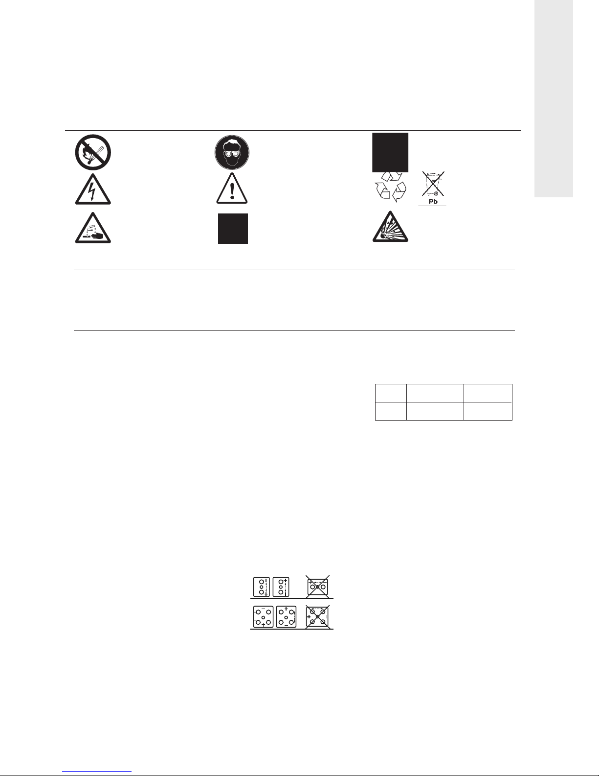
No smoking no naked
flames, no sparks
Electrical hazard
Electrolyte is corrosive,
in case of broken
containers/lids
Shield eyes
Danger
Clean all acid splash in eyes or
on skin with lot of clear water.
T
hen visit a doctor.
Acid on clothing is to be washed
with water.
+
Note operating
instructions
Recycle scrap
batteries.
Contains lead
Warning: Risk of fire, explosion, or
burns. Do not disassemble, heat
above 60ºC, or incinerate. Avoid
any short circuit. Metallic parts
under voltage on the battery, do not place tools
or items on top of the battery
DELIVERY AND STORAGE
Inspect for signs of damage or missing
components.
Store the battery in a dry, clean and
preferably cool and frost-free location. Do not
expose the cells to direct sunlight as damage
to the container and cover may occur. As the
batteries are supplied charged, storage time is
limited. In order to easily charge the batteries
after prolonged storage, it is advised not to
store it more than
6 months at 20°C
4 months at 30°C
2 months at 40°C
A refreshing charge shall be performed after
this time or if the open circuit voltage is below
2.07 Vpc.
Failure to observe these conditions may result
in greatly reduced capacity and service life.
The refreshing charge shall be carried out
according to clause a) of the commissioning
charge paragraph below. Alternatively the cells
can be float-charged at 2.25 Vpc during
storage.
INSTALLATION
The electrical protective measures and the
accommodation and ventilation of the
battery installation must be in accordance with
the applicable rules and regulations.
Specifically EN 50272-2 applies.
Do not use terminal posts to lift or handle
cells.
The battery should be installed in a clean, dry
area. It will not emit corrosive gases in normal
operation and can be installed together with
other electrical equipment. Under normal
conditions the gas release is negligible and
natural ventilation is sufficient for cooling
purposes and inadvertent overcharge,
enabling OPzV batteries to be used safely in
offices or within equipment. However care
must be taken to ensure adequate ventilation
when placed in cabinets. They must not be
placed in sealed cabinets without ventilation
openings at the top and bottom. Avoid placing
the battery in a warm place or in direct
sunlight. Approved battery racks are
recommended for proper installation. Place
the cells on the rack and arrange the positive
and the negative terminals for connection
according the wiring diagram.
Horizontal Installation
Do not use terminal posts to lift or handle
cells.
Do not install the cells in such a way that the
box-lid bond is resting on a runner. Always
ensure that the arrow on the lid of each unit is
pointing in vertical orientation.
Do not invert cells (vents upside down) or
allow the front of the cells to be positioned
lower than the base of the cell as it might
block the safety valve and damage pillars.
Check that all contact surfaces are clean. If
required clean with a brass brush. Tighten the
terminal screws, taking care to use the correct
torque loading (Tab. 1). To avoid damage to
the plastic materials, do not use grease. Fit the
covers supplied for protection against
inadvertent contact.
Tab. 1: Torque loadings for terminal screws
Type Terminal screw Torque
OPzV M10 23 – 25 Nm
Carefully follow the polarity sequence to avoid
short circuiting cell groups. A loose connector
can make adjusting the charger difficult,
create erratic performance and possible
damage to the battery and/or even personal
injury. Finally, with the charger switched off,
the battery fuses removed and the load
disconnected, connect the battery to the D.C.
power supply.
Ensure that the polarity is correct positive terminal of the battery to the positive
terminal of the charger. Switch on the charger
and charge according to the commissioning
charge paragraph below. The first charge must
be monitored to ensure that the limits are not
exceeded and that no unacceptable
temperatures occur.
Cells or monoblocs in parallel strings
OPzV cells monoblocs may be connected in
parallel to give higher current capability. In the
case of parallel connected strings, use
batteries of the same capacity, design and age
only with a maximum of 4 parallel strings. The
resistance of the cables in each string must be
the same, e.g. same cross-section, same length.
Connect the battery strings in parallel at the
charger terminals
1
Page 3
C
OMMISSIONING CHARGE
When commissioning a new battery (first
charge), follow procedure a) or b).
Procedure a) is recommended.
a
) IU method (boost charge):
A
t a raised voltage of 2.33 – 2.40 Vpc. The
charging time will be 12 to 24 hours depending on the initial charge condition. The current must be limited to 4 x I
1
0
.
Boost charging must be switched off or switched over to float charging as soon as the
fully charged state is reached.
b
) Float charge:
With a voltage of 2.25 Vpc. Full capacity will
b
e obtained after a longer period of 4 to 6
weeks depending on state of charge.
STANDBY OPERATION /FLOAT
CHARGE
Float Voltage
The recommended float / charge voltage
is 2.25 V per cell at 20°C (tolerance 2.23 –
2.25 Vpc). The charger voltage amounts to
2.25 Vpc x no. of cells. If the average ambient
temperature deviates more than ± 10°C
from the reference temperature of 20°C, it is
recommended to adjust the float voltage to
the following temperature compensation
curve:
Temperature Float voltage
-10 °C 2,37 Vpc
0 °C 2,33 Vpc
10 °C 2,29 Vpc
20 °C 2,25 Vpc
30 °C 2,23 Vpc
40 °C 2,21 Vpc
In case that the average temperature
deviates less than ±5°C, no temperature
compensation has to be applied.
The recommended float charge voltage is
2.25 volts per cell at 20°C. Following a
commission charge and after 6 months
continuous charge at the recommended
float voltage, individual cell voltages will
stabilise within ±4.5% of the mean applied
voltage.
However, immediately following commissioning and for the initial 6 months of
continuous float charge, individual cell
voltage values outside the above tolerance
may be observed without adverse efect.
There is no relationship between a cell’s float
voltage and its discharge capacity. Cells are
prefectly capable of giving their discharge
capacity even when outside the ±4.5% range.
After 6 months service, should any individual
cell show a continuing reduction or increase
in voltage outside the above limits over
3 successive monthly periods, our sales
department should be contacted for advice.
Charging Current
Limitation of the charging current is not
required under float charge condition at
2.25 Vpc. At higher charge voltages the
charge current shall be limited to 4 x I
10
.
B
oost Charge
To reduce the recharge time the battery may
be recharged at 2.33 – 2.40 V per cell with a
c
urrent limited to 4 x I
10
. Fast charging must
be switched over to float charging when the
f
ully charged state is reached.
Ripple Current
In the standby operation mode the effective
value of the A.C. ripple current must not
e
xceed 5 A/100Ah C10, otherwise reduced
operational life must be expected.
TEMPERATURE
The recommended operating temperature
range is -10°C to +45°C. The battery will give
best performance and service life when working in the temperature range of +10°C to
+30°C. Higher temperatures reduce the operational life. Lower temperatures reduce the
available capacity. Temporary peak temperatures shall not exceed –30°C and +55°C.
Consideration must be given to depth of discharge (low temperatures) and ventilation
(high temperatures). All technical data relates
to the rated temperature of +20°C. Do not
expose cells to direct sunlight.
DISCHARGING
End of Discharge Voltage
The battery must not be discharged more
than the capacity specified in the performance tables. Deeper discharges may damage the
battery and shorten its operational life. As a
general rule the end of discharge voltage
shall be limited to the values listed below:
Discharge time
1h < t < 5h 1.70 Vpc
5h < t < 8h 1.75 Vpc
8h < t < 24h 1.80 Vpc
Individual cell voltages may fall below U
E
by
not more than 0.2 Vpc. A low voltage disconnect is recommended to prevent deep
discharge. Special attention should be given
to small loads that are not automatically disconnected at the end of discharge.
Discharged Cells and monoblocs
OPzV batteries must not be left in a discharged
condition after supplying the load but must be
immediately returned to recharge mode. Failure
to observe these conditions may result in greatly
reduced service life and unreliability.
Accidental Deep Discharge
Following accidental deep discharge, the battery must be recharged at 2.25 Vpc followed by
an equalizing charge. As the internal resistance
is high at first, the initial charge current is low.
Important notice:
Each deep discharge is abusive, and could
affect the life expectancy of the battery.
TESTING
Capacity tests are to be carried out in accor-
dance with EN 60896-2. Check that the bat-
tery is fully charged. Before testing new bat-
teries it must be ensured that a sufficient
commissioning charge has been applied.
Temperature correction factor
The temperature has an effect on the battery
capacity. The following table shows the correction factors for temperatures other than
the reference temperature of 20°C.
RECHARGE
After a discharge the battery can be recharged
at the operating voltage (float charge voltage).
Depending on the depth of discharge this may
t
ake up to 3 days. To reduce the charging time
the recharging can be carried out with a boost
charge voltage of 2.33 to 2.40 Vpc (fast charge). The recharging times are dependent on
the depth of discharge and on the charging
current available. Generally, 10 to 20 hours
duration can be expected at charging currents
between 5A and 40A per 100Ah C
10
. Fast charging must be switched over to float charging
when the fully charged state is reached.
Equalising charge
Under exceptional circumstances only, e.g.
after deep discharges or after repeated
inadequate recharging, an equalising charge
shall be carried out according to clause a) of
the commissioning charge paragraph or with
the following IUI characteristic:
Charge at increased voltage of 2.33 – 2.40
Vpc, then continue with a constant current of
1.5 A per 100 Ah C
10
during which individual
cell voltages can be allowed to rise to 2.60 –
2.65 Vpc maximum. The charging must be
monitored. The charging time at constant
current shall be 5 to 10 hours.
MAINTENANCE/CHECKS
OPzV batteries are maintenance free, sealed,
lead acid batteries and do not have to be topped up with water or electrolyte. The containers and lids should be kept dry and free
from dust. Cleaning must be undertaken with
a damp cotton cloth without man-made fibres or addition of cleaning agents. Avoid static discharges generated during cleaning.
Every 6 months, check the total voltage at the
battery terminals, the cell voltages of pilot
cells and the temperature. Once a year, in
addition to the above, take readings of individual cell voltages. Keep a logbook in which
the measured values can be noted as well as
power cuts, discharge tests, etc.
Do not
attempt to open the safety valve. Opening
could cause lasting damage to the battery
and is prohibited.
SPECIAL APPLICATIONS
Whenever OPzV batteries are to be used
for special applications such as repeated
cycling or under extreme ambient conditions please contact your SALES OFFICE.
For further information please visit our
website: www.enersys-emea.com
D
ischargeTemperature in °C
T
ime -100+10 +20 +30 +40
5
-12 hours 0.60 0.78 0.90 1.00 1.05 1.07
1-4 hours 0.55 0.74 0.88 1.00 1.06 1.08
End voltage
2
Capacity tests are to be carried out in accordance with EN 60896-21/22. Check that the
battery is fully charged. Before testing new
batteries it must be ensured that a sufficient
commissioning charge has been applied.
Page 4
FRANÇAIS
3
PowerSafe OPzV
Consignes d’installation,
d’exploitation et de maintenance
Manipulation
Le s batte rie s OPzV sont e xpé diées c har gée s ; il faut
les déballer avec précaution pour éviter tout
courant de court-circuit entre bornes de polarités
opposées.
Les éléments sont lourds et doivent être levés avec
des systèmes de levage appropriés.
Eviter toute étincelle
En cas de surcharge accidentelle, un gaz inflammable
peut s’échapper de la valve de sécurité. Se
“décharger” régulièrement à la terre de toute
électricité statique en touchant une partie métallique
Outillage
Utiliser des outils dont le manche est isolé. Ne pas
placer ou laisser tomber des objets métalliques sur la
batterie.
Oter bagues, montre et pièces d’habillement
comportant des parties métalliques qui pourraient
entrer en contact avec les bornes de la batterie.
Ne pas fumer
Ni flammes nues
Ni étincelles
D
anger électrique
L’electrolyte est corrosif.
Attention aux couvercles
et bacs cassés
Porter des lunettes
de protection
D
anger
Nettoyer toute projection d’acide sur
la peau ou dans les yeux à l’eau claire.
Consulter un médecin. Les vêtements
contaminés sont à laver avec de l’eau.
+
Se conformer
à la notice d’emploi
R
ecycler les
composants
batterie. Contient
d
u plomb
Attention : Risque d'incendie,
d’explosion ou de brûlures. Ne pas
démonter, chauffer au-delà de 60ºC
ou jeter au feu. Eviter tout courtcircuit. Pièces métalliques sous
tension sur la batterie. Ne pas déposer
d’objets ou outils sur la batterie
RECEPTION ET STOCKAGE
Contrôler tout signe de dégradation ou
toute pièce manquante dans le colisage.
Stocker la batterie dans un endroit sec,
propre et de préférence frais et à l’abri du
gel. Ne pas exposer les éléments
directement à la lumière du soleil, pouvant
entraîner des dommages sur les bacs et
couvercles.
Comme les batteries sont expédiées
chargées, le temps de stockage est limité.
Afin de recharger facilement les batteries
après une période prolongée, il est conseillé
de ne pas dépasser un temps de stockage
sans recharge de :
6 mois à 20°C
4 mois à 30°C
2 mois à 40°C
On effectuera alors une recharge après
cette période ou si la tension de circuit
ouvert est inférieure à 2.07 V/élément.
Le non-respect de ces consignes portera
préjudice à la capacité et la durée de vie de
la batterie.
La recharge doit être réalisée selon le
paragraphe a) du chapitre Charge de mise
en service. Autrement, les éléments
peuvent être chargés en floating à 2.25
V/élément pendant le stockage.
INSTALLATION
Les mesures de protection électrique,
l’emplacement et la ventilation de
l’installation de la batterie doivent être
conformes aux normes et réglements en
vigueur. La norme EN 50272-2 s’applique
tout particulièrement.
La batterie doit être installée dans un
endroit sec et propre. Ne dégageant pas de
gaz corrosif en fonctionnement normal,
elle peut être installée près de tout autre
matériel électrique.
Dans des conditions normales, le
dégagement gazeux est très faible et une
ventilation naturelle est suffisante pour
tout refroidissement et surcharge acci-
dentelle, permettant aux batteries OPzV
d’être utilisées en toute sécurité autant
dans des bureaux que dans les ateliers.
Cependant, il est nécessaire d’assurer une
aération adéquate pour les batteries
montées en armoires, elles ne doivent pas
être installées dans des armoires fermées
sans ouies d’aération en haut et en bas de
l’armoire.
Eviter de placer la batterie dans un endroit
chaud ou derrière une fenêtre exposée au
soleil. Les chantiers pour batteries sont
recommandés pour une installation
appropriée. Placer les éléments sur le
chantier et se référer au plan pour la
position correcte des polarités.
Installation horizontale
Ne pas installer les éléments de telle façon
que la liaison bac/couvercle soit placée sur
un longeron. S’assurer que les plaques
soient verticales.
Contrôler que toutes les surfaces de contact
sont propres. Si nécessaire, nettoyer avec
une brosse laiton. Serrer les écrous en
prenant soin d’utiliser le couple de serrage
adéquat (Tab. 1). Pour éviter toute
détérioration de la matière plastique ne pas
utiliser de graisse. Placer les capots de
protection contre le contact direct.
Tab. 1 : Couple de serrage des boulons
d’interconnexion
Type Vis Serrage
OPzV M10 23 – 25 Nm
Suivre la polarité pour éviter les courts-
circuits. Une connexion mal serrée peut
entraîner des problèmes pour le réglage du
chargeur, un fonctionnement hétérogène
de la batterie et porter préjudice à la
batterie et/ou au personnel.
Enfin connecter la batterie à l’alimentation
en courant continu, avec le chargeur coupé
les fusibles batteries retirés et la charge
déconnectée.
S’assurer que la polarité est correcte, borne
positive de la batterie à la borne positive du
chargeur.Connecter le chargeur et la charge
en se référant au chapitre Charge de mise
en service. La première charge doit être
surveillée afin de ne pas dépasser les limites
et de ne pas atteindre des températures
inacceptables.
Montage des éléments en parallèle
Les éléments OPzV peuvent être connectés
en parallèle pour fournir une capacité plus
élevée. Pour ce type de montage, utiliser
uniquement des batteries de même
capacité, conception et âge avec un
maximum de 4 branches en parallèle pour
des raisons pratiques. La résistance des
câbles dans chaque branche doit être
la même, c’est-à-dire même section,
même longueur. Connecter les branches
en parallèle aux bornes terminales.
Garantie
Le non-respect des consignes d’installation, d’exploitation et de maintenance, des réparations avec des pièces détachées non homologuées, une utilisation non conforme avec
les consignes, l’addition de produits divers à l’électrolyte et l’interférence non autorisée avec la batterie invalident toute réclamation au titre de la garantie.
RECEPTION ET STOCKAGE
Contrôler tout signe de dégradation ou toute
pi
èce manquante dans le colisage. Stocker la
batterie dans un endroit sec, propre et de
préférence frais et
à l’abri du gel. Ne pas
exposer les éléments directement
à la lumière
du soleil, pouvant
entraîner des dommages
sur les bacs et couvercles.
Comme les batteries sont expédiées chargées,
le temps de stockage est limité.
Afin de recharger facilement les batteries
apr
ès une période prolongée, il est conseillé
de ne pas dépasser un temps de stockage sans
recharge de :
6 mois
à 20°C
4 mois
à 30°C
2 mois
à 40°C
On effectuera alors une recharge apr
ès cette
période ou si la tension de circuit ouvert est
inférieure
à 2.07 V/élément.
Le non-respect de ces consignes portera
préjudice
à la capacité et la durée de vie de
la batterie.
La recharge doit
être réalisée selon le
paragraphe a) du chapitre Charge de mise en
service. Autrement, les éléments peuvent tre
chargés en floating
à 2.25 V/élément pendant
le stockage.
INSTALLATION
Les mesures de protection électrique,
l’emplacement et la ventilation de l’installation
de la batterie doivent
être conformes aux
normes et réglements en vigueur. La norme EN
50272-2 s’applique tout particuli
èrement.
Ne pas soulever ou manipuler les éléments par
les bornes.
La batterie doit
être installée dans un endroit
sec et propre. Ne dégageant pas de gaz
corrosif en fonctionnement normal, elle peut
être installée près de tout autre matériel
électrique.
Dans des conditions normales, le dégagement
gazeux est tr
ès faible et une ventilation
naturelle est suffisante pour tout
refroidissement et surcharge accidentelle,
permettant aux batteries OPzV d’
être utilisées
en toute sécurité autant dans des bureaux que
dans les ateliers.
Cependant, il est nécessaire d’assurer une
aération adéquate pour les batteries montées
en armoires, elles ne doivent pas
être
installées dans des armoires fermées sans
ouies d’aération en haut et en bas de
l’armoire.
Eviter de placer la batterie dans un endroit
chaud ou derri
ère une fenêtre exposée au
soleil. Les chantiers pour batteries sont
recommandés pour une installation
appropriée. Placer les éléments sur le chantier
et se référer au plan pour la position correcte
des polarités.
Installation horizontale
Ne pas soulever ou manipuler les éléments par
les bornes. Ne pas installer les éléments de
telle fa
çon que la liaison bac/couvercle soit
placée sur un longeron.
S'assurer que la fl
èche présente sur les
couvercles soit toujours verticale.
Ne pas inverser les éléments (syst
ème de
dégazage
à l'envers). A aucun moment le haut
des éléments ne doit
être positionné plus bas
que la base des éléments car ceci pourrait
boucher les valves de securité et endommager
les bornes. Contrôler que toutes les surfaces
de contact sont propres. Si nécessaire,
nettoyer avec une brosse laiton. Serrer les
écrous en prenant soin d’utiliser le couple de
serrage adéquat (Tab. 1). Pour éviter toute
détérioration de la mati
ère plastique ne pas
utiliser de graisse. Placer les capots de
protection contre le contact direct.
Tab. 1 : Couple de serrage des boulons
d’interconnexion
Type Vis Serrage
OPzV M10 23 – 25 Nm
Suivre la polarité pour éviter les courtscircuits. Une connexion mal serrée peut
entraîner des problèmes pour le réglage du
chargeur, un fonctionnement hétérog
è ne de
la batterie et porter préjudice
à la batterie
et/ou au personnel.
Enfin connecter la batterie
à l’alimentation en
courant continu, avec le chargeur coupé les
fusibles batteries retirés et la charge
déconnectée.
S’assurer que la polarité est correcte, borne
positive de la batterie
à la borne positive du
chargeur. Connecter le chargeur et la charge
en se référant au chapitre Charge de mise en
service. La premi
ère charge doit être surveillée
afin de ne pas dépasser les limites et de ne pas
atteindre des températures inacceptables.
Montage des éléments en parall
èle
Les éléments OPzV peuvent
être connectés en
parall
èle pour fournir une capacité plus
élevée. Pour ce type de montage, utiliser
uniquement des batteries de m
ême capacité,
conception et
âge avec un maximum de 4
branches en parall
èle pour des raisons
pratiques. La résistance des c
âbles dans
chaque branche doit
être la même, c’est-à-
dire m
ême section, même longueur.
Connecter les branches en parall
èle aux
bornes terminales.
3
Page 5

CHARGE DE MISE EN SERVICE
Lors de la mise en service d’une batterie
neuve (première charge), la procédure peut
être la suivante (procédure a) recommandée):
a) courbe IU (charge rapide) :
à tension augmentée de 2.33 – 2.40 V/ élément.
Le temps de charge sera de 12 à
24 heures en fonction des conditions de
charge initiale. Le courant sera limité à 4xI
1
0
La charge rapide peut être arrêtée ou
transformée en charge de floating quand
l’état de charge est atteint.
b) charge de floating :
avec une tension de 2.25 V/élément.
La pleine capacité sera atteinte après
une longue péroide de 4 à 6 semaines en
fonction de l’état de charge.
APPLICATION STATIONNAIRE/
TENSION DE FLOATING
Tension de floating
La tension de floating/charge recommandée est 2.25 V par élément à 20°C
(tolérance 2.23 – 2.25 V/élément).
La tension du chargeur est de 2.25 V/
élément x nombre d’éléments. Quand la
température moyenne ambiante varie de
± 10°C par rapport à la température de
référence de 20°C, il est recommandé de
régler la tension de floating comme suit:
TempératureTension de floating
-10 °C 2,37 V/élément
0 °C 2,33 V/élément
10 °C 2,29 V/élément
20 °C 2,25 V/élément
30 °C 2,23 V/élément
40 °C 2,21 V/élément
On peut toutefois renoncer à un réglage, si
les variations de température de fonctionnement moyenne sont inférieures à +/- 5°C
par rapport à la température nominale.
La tension de floating recommandée est de
2.25 volts par élément à 20°C. Suite à la
charge de mise en service et après 6 mois à
la tension de floating recommandée, les
tensions individuelles des éléments se
stabiliseront dans une plage de ±4.5% par
rapport à la tension moyenne de la batterie.
Cependant, immédiatement après la mise
en service et pendant les 6 premiers mois
en tension de floating continue, il se peut
que l’on observe des valeurs de tension
individuelle par élément en dehors des
limites ci-dessus, sans causer d’effet
défavorable. Il n’y a pas de rapport entre
la tension de floating d’un élément et sa
capacité de décharge. Les éléments sont
parfaitement capables de fournir la
capacité demandée même lorsqu’ils sont
en dehors de la plage de ±4.5%.
Après 6 mois de service, dans le cas où la tension d’un élément serait en dehors des limites
ci-dessus pendant plus de 3 mois successifs, il
faudrait alors contacter le service commercial.
Courant de charge
La limitation du courant de charge des
batteries n’est pas nécessaire pour une charge
de floating inférieure à 2.25 V/élément.
Pour des tensions de charge plus élevées le
courant de charge sera limité à 0.4 x I
1
0
Recharge rapide
Pour réduire le temps de recharge, la
batterie peut être rechargée à 2.33 – 2.40 V
par élément avec un courant limité à
0.4 x I
1
0
. La recharge rapide peut passer en
charge de floating quand la batterie a
atteint son plein état de charge.
Courant ondulatoire
En application stationnaire la valeur effective
du courant ondulatoire alternatif ne doit pas
dépasser 5A/100Ah C
10
, entraînant sinon
une réduction de la durée de vie.
TEMPERATURE
La température recommandée d’exploitation est -10°C à +45°C. La batterie offrira
les meilleures performances et durée de vie
en exploitation de +10°C à +30°C. Des
températures plus élevées réduisent la durée
de vie. Des températures inférieures
réduisent la capacité. Des pointes de
température temporaires ne peuvent
dépasser –30°C et +55°C en tenant compte
de la profondeur de décharge (basses
températures) et de la ventilation (températures élevées). Toutes les données techniques
se réfèrent à la température de +20°C.
Ne pas exposer les éléments au soleil direct.
DECHARGE
Tension de fin de décharge
La batterie ne doit pas être déchargée plus
profondément que la capacité spécifiée dans
les tableaux de performances. Des décharges
plus profondes peuvent porter préjudice à la
batterie et réduire sa durée de vie. En règle
générale, la tension de fin de décharge doit
être limitée aux valeurs ci-dessous:
Durée décharge
1h < t < 5h 1.70 V/élement
5h < t < 8h 1.75 V/élement
8h < t < 24h 1.80 V/élement
Les tensions individuelles ne doivent jamais
être inférieures de plus de 0,2 V/élément par
rapport à la tension finale. Une coupure à
faible tension est recommandée pour éviter
la décharge profonde. Faire attention aux
petits équipements qui ne sont pas automatiquement déconnectés à la fin de la décharge.
Eléments déchargés
Les batteries OPzV ne doivent pas rester
déchargées après avoir fourni une charge
mais doivent immédiatement subir une
recharge. Le non respect de ces consignes
peut porter préjudice à la durée de vie et à
la fiabilité de la batterie.
Décharge profonde accidentelle
La batterie doit être rechargée à 2.25V/élément
suivi d’une charge d’égalisation. Comme la
résistance interne est élevée au départ, le
courant de charge initial est faible.
Remarque importante:
Chaque décharge profonde est abusive et
aura des incidences sur la durée de vie.
TESTS
Des tests de capacité peuvent être
effectués, dans ce cas selon la norme
EN 60896-2. Vérifier que la batterie est
pleinement chargée. Avant de tester les
nouvelles batteries, s’assurer qu’une charge
de mise en service suffisante a été réalisée.
Facteur de correction de la température
La température a un effet sur la capacité de
la batterie. Le tableau suivant donne le
facteur de correction pour une température
de référence de 20°C.
RECHARGE
Après une décharge la batterie peut être
rechargée à la tension d’exploitation (tension
de charge de floating). En fonction de la
profondeur de décharge ceci peut aller jusque
3 jours. Afin de réduire le temps de charge, la
recharge peut être effectuée avec une tension
de charge rapide de 2.33 à 2.40 V/élément. Les
temps de recharge dépendent de la
profondeur de décharge et du courant de
charge disponible; en règle générale ils vont de
10 à 20 heures pour des courants de charge
entre 5A et 40A pour 100Ah C
1
0
.
La charge rapide doit passer en charge de
floating quand la pleine charge est atteinte.
Charge d’égalisation
Dans des circonstances exceptionnelles uniquement, c’est-à-dire, après des décharges profondes
ou après des recharges répétées inappropriées,
une charge d’égalisation peut être opérée selon
le paragraphe a) du chapitre Charge de mise en
service ou avec la courbe IU suivante :
Charge à tension augmentée 2.33 –
2.40 V/élément,puis poursuite avec un courant
constant de 1.5 A pour 100 Ah C
10
pendant
lequel les tensions de chaque élément peuvent
atteindre 2.60 – 2.65 V/élément maximum. La
charge doit être surveillée. Le temps de charge
à courant constant doit être de 5 à 10 heures.
MAINTENANCE/CONTROLES
Les éléments OPzV sont des batteries plomb
acide sans entretien, étanches et n’ont pas
besoin de remise en eau. Les bacs et
couvercles doivent être toujours secs et
exempts de poussière. Nettoyer exclusivement avec un chiffon en coton humide
sans fibres synthétiques ni addition d’agents
de nettoyage. Evi ter la charge électrostatique.
Tous les 6 mois, vérifier la tension totale aux
bornes de la batterie, et les tensions unitaires
des éléments pilotes et la température. Une
fois par an, effectuer un relevé de tension des
éléments. Tenir un cahier de bord dans lequel
seront notées les valeurs mesurées ainsi que
les coupures secteur, les tests de décharge, etc.
Ne pas ouvrir la valve. L’ouverture cau serait la
dégradation irréversible de la batterie et est
interdite.
APPLICATIONS SPECIALES
Si la OPzV doit être utilisée dans des
applications spéciales comme du cyclage
répété ou dans des conditions d’environnement extrêmes, veuillez contacter votre
SERVICE COMMERCIAL.
Pour plus d’information, consulter notre site
web www.enersys-emea.com
D
urée de Température en °C
décharge -100+10 +20 +30 +40
5
-12 heures 0.60 0.78 0.90 1.00 1.05 1.07
1
-4 heures 0.55 0.74 0.88 1.00 1.06 1.08
Tension nale
4
Des tests de capacité peuvent être
effectu
é s, dans ce cas selon la norme EN
60896-21/22. V
é rifier que la batterie est
pleinement charg
é e. Avant de tester les
nouvelles batteries, s’assurer qu’une charge
de mise en service suffisante a
é té réalisée.
Page 6

PowerSafe OPzV
Gebrauchsanweisung
und Bedienungsanleitung
ANLIEFERUNG UND LAGERUNG
Die Batterien und das Zubehör sind bei
Anlieferung auf einwandfreien Zustand und
Vollständigkeit zu prüfen. Die Batterien sind an
einem trockenen, kühlen, aber frostfreien Ort
zu lagern. Sie dürfen keinem direkten Sonnen-
licht ausgesetzt sein, da sonst Schäden an
Gefäß und Deckel auftreten können.
Die Batterien sind ohne Ladung nur begrenzt
lagerfähig. Ist die Batterie nicht auf Erhal-
tungsladung, sind periodisch nach folgenden
Zeitabständen Nachladungen durchzuführen:
6 Monate bei 20°C
4 Monate bei 30°C
2 Monate bei 40°C
Eine Nachladung ist auch dann erforderlich,
wenn die Ruhespannung unter 2,07 V/Zelle
liegt.Bei Nichtbeachtung der Nachladeinter-
valle kann die Batterie dauerhaft geschädigt
werden, d.h., Kapazität und Gebrauchsdauer
sind stark reduziert.
Die Nachladung hat nach Punkt a), Kapitel
Inbetriebsetzung, zu erfolgen. Alternativ
können die Zellen dauerhaft unter Erhal-
tungsladung mit 2,25 V/Zelle gelagert werden.
AUFSTELLUNG
Die elektrischen Schutzmaßnahmen, die
Unterbringung und die Belüftung der
Batterieanlage müssen den geltenden
Vorschriften und Regeln entsprechen,
insbesondere gilt EN 50272-2. OPzV Batterien
geben unter normalen Betriebsbedingungen
keine korrosiven Gase ab. Sie können
daher unter Beachtung des vorgeschriebenen
Luftabstandes zusammen mit elektrischen
Geräten betrieben werden. Die Aufstellung
sollte nicht an Orten mit hoher oder räumlich
ungleichmäßiger Wärmebelastung erfolgen.
Direktes Sonnenlicht (zum Beispiel an
Fenstern) ist zu vermeiden. Für die Aufstellung
werden Gestelle empfohlen. Zellen gemäß
Aufstellungsplan aufstellen und mit
Verbindern schaltungsrichtig verbinden.
Polarität beachten, um Kurzschlüsse zu
vermeiden.
Horziontale Aufstellung
Die Verbindungsnaht zwischen Gefäß und
Deckel darf nicht auf dem Gestell aufliegen.
Die Zellen sind so zu orientieren, daß die
Elektroden vertikal stehen:
Die Kontaktflächen an den Polen und an den
Verbindern müssen sauber sein, eventuell mit
Messingdrahtbürste reinigen. Es darf kein Fett
verwendet werden, da dies unter Umständen
den Kunststoff schädigt. Polschrauben unter
Beachtung des Anzugsdrehmoments (Tab.1)
anziehen. Für den Berührungsschutz
mitgelieferte Abdeckungen anbringen.
Tab. 1: Anzugsdrehmonent
Typ Polschraube Anzugsdrehmoment
OPzV M10 23 – 25 Nm
Ein loser Verbinder kann zu einer falschen
Einstellung des Ladegerätes führen, beein-
trächtigt die Batterieleistung und kann
erhebliche Schäden an Batterie oder an Perso-
nen verursachen. Batterie polaritätsrichtig
(positiven Pol der Batterie an positive
Anschlußklemme) bei ausgeschaltetem
Ladegerät, entfernten Batterie-sicherungen
und abgetrennten Verbrauchern an die Gleich-
stromversorgung anschließen. Ladegerät
einschalten und gemäß Kapitel Inbetriebset-
zung laden. Die erste Ladung ist zu überwachen,
damit keine Überschreitung von Grenzwerten
oder unzulässigen Temperaturen auftritt.
Parallelschaltung
OPzV Zellen Blockbatterien können parallel
geschaltet werden, um höhere Kapazitäten
zu erzielen. Bei Parallelschaltungen wird
empfohlen, nur Batterien gleicher Kapazität,
gleicher Bauart und gleichen Alters in maximal
4 parallelen Strängen einzusetzen. Die Wider-
standswerte der Leitungen im jeweiligen Strang
müssen möglichst gleich sein (z.B. gleicher
Querschnitt, gleiche Länge). Die P arallelschaltung
erfolgt an den Endpolen der Batteriestränge.
INBETRIEBSETZUNG
Die Inbetriebsetzung einer neuen Batterie
(erste Ladung) kann wie folgt durchgeführt
werden (Methode a empfohlen):
a) IU Kennlinie (Starkladung):
mit erhöhter Spannung von 2,33 –
2,40V/Zelle. Die Ladezeit beträgt je nach
Anfangsladezustand 12 bis 24 Stunden. Der
Ladestrom sollte 4 x I
10
nicht überschreiten.
Nach Erreichen des Volladezustandes ist
abzuschalten oder auf Erhaltungsladen
umzuschalten.
DEUTSCH
Vorsichtshinweise
Berührbare Metallteile der Batterie führen
i
mmer Spannung und sind elektrisch aktive
T
eile. Kurzschluß vermeiden. Nur isolierte
W
erkzeuge verwenden. Bei der Arbeit keine
m
etallischen Gegenstände tragen. Die beim
L
aden entstehenden Gase sind explosiv.
Elektrostatische Aufladung, insbesondere von
Kleidung, vermeiden. Die nach EN 50272-2
festgelegten Schutzmaßnahmen sind
anzuwenden.
B
ei Nichtbeachtung der Gebrauchsanweisung,
R
eparatur mit nicht originalen Ersatzteilen, nicht
b
estimmungsgemäßem Gebrauch, Anwendung von
Zusätzen zum Elektrolyt und eigenmächtigen
Eingriffen erlischt der Gewährleistungsanspruch
Rücknahme und Entsorgung gebrauchter Batterien nach der Batterieverordnung (BattV)
G
ebrauchte Batterien mit dem Recycling-Zeichen (Pb) enthalten wiederverwertbares Wirtschaftsgut.
Gemäß der Kennzeichung mit der durchgestrichenen Mülltonne dürfen diese Batterien nicht dem
Hausmüll beigegeben werden. Die Rücknahme und Verwertung sind gemäß §8 BattV mit dem
Hersteller oder Vertreiber zu vereinbaren und entsprechend sicherzustellen
Rauchen verboten! Von
offenen Flammen und
F
unken fernhalten, da
E
xplosions- und Brandgefahr
Gefährliche Spannung
(bei Spannungen >60Vdc)
E
lektrolyt ist stark ätzend. Im normalen
Betrieb ist Berührung mit dem
Elektrolyten ausgeschlossen. Bei
Z
erstörung der Gehäuse ist der
f
reiwerdende gebundene Elektrolyt
g
enauso ätzend wie flüssiger
Bei Arbeiten an Batterien Schutzbrille
und Schutz- kleidung tragen,
Unfallverhütungsvorschriften
beachten
Vorsicht Blockbatterien / Zellen
haben großes Gewicht ! Auf sichere
Aufstellung achten ! Nur geeignete
Transporteinrichtung verwenden
- Säurespitzer i m Auge oder auf der Haut mit
viel klarem Wasser aus-bzw. abspülen.
- Danach unverzüglich einen Arzt aufsuchen
- Mit Säure verunreinigte Kleidung mit
Wasser auswachen
+
Gebrauchsanweisung lesen
und in der Nähe der Batterie
anbringen
Warnung: Gefahr von Brand, Explosion
oder Verbrennungen. Nicht zerlegen
oder verbrennen bei einer Hitzeüber
60°C. Kurzschlüsse vermeiden! Metallteile
der Batterie stehen immer unter
Spannung, deshalb keine Gegenstände
oder Werkzeuge auf der Batterie ablegen
ANLIEFERUNG UND LAGERUNG
Die Batterien und das Zubehör sind bei
Anlieferung auf einwandfreien Zustand und
Vollständigkeit zu prufen. Die Batterien sind an
einem trockenen, ku hlen, aber frostfreien Ort
zu lagern. Sie du rfen keinem direkten
Sonnenlicht ausgesetzt sein, da sonst Schäden an
Gefäß und Deckel auftreten können.
Die Batterien sind ohne Ladung nur begrenzt
lagerfähig. Ist die Batterie nicht auf
Erhaltungsladung, sind periodisch nach folgenden
Zeitabständen Nachladungen durchzufu hren:
6 Monate bei 20°C
4 Monate bei 30°C
2 Monate bei 40°C
Eine Nachladung ist auch dann erforderlich, wenn
die Ruhespannung unter 2,07 V/Zelle liegt. Bei
Nichtbeachtung der Nachladeintervalle kann die
Batterie dauerhaft geschädigt werden, d.h.,
Kapazität und Gebrauchsdauer sind stark
reduziert. Die Nachladung hat nach Punkt a),
Kapitel Inbetriebsetzung, zu erfolgen. Alternativ
können die Zellen dauerhaft unter
Erhaltungsladung mit 2,25 V/Zelle gelagert
werden.
AUFSTELLUNG
Die Anschlusspole keinesfalls zum Transport bzw.
Anheben der Zellen verwenden!
Die elektrischen Schutzmaßnahmen, die
Unterbringung und die Belu ftung der
Batterieanlage mu ssen den geltenden
Vorschriften und Regeln entsprechen,
insbesondere gilt EN 50272-2. OPzV Batterien
geben unter normalen Betriebsbedingungen
keine korrosiven Gase ab. Sie können daher unter
Beachtung des vorgeschriebenen Luftabstandes
zusammen mit elektrischen Geräten betrieben
werden. Die Aufstellung
sollte nicht an Orten mit hoher oder räumlich
ungleichmäßiger Wärmebelastung erfolgen.
Direktes Sonnenlicht (zum Beispiel an Fenstern)
ist zu vermeiden. Fu r die Aufstellung werden
Gestelle empfohlen. Zellen gemäß
Aufstellungsplan aufstellen und mit Verbindern
schaltungsrichtig verbinden. Polarität beachten,
um Kurzschlusse zu vermeiden.
Horziontale Aufstellung
Die Anschlusspole keinesfalls zum Transport
bzw. Anheben der Zellen verwenden!
Die Verbindungsnaht zwischen Gefäß und Deckel
darf nicht auf dem Gestell aufliegen.
Achten Sie darauf, dass der Pfeil auf dem Deckel
jeder Zelle immer in vertikale Ausrichtung zeigt.
Die Kontaktflächen an den Polen und an den
Die Zellen keinesfalls umdrehen (Ventil nach
unten). Weiter ist darauf zu achten, dass die
Zellen bei waagerechter Montage hinten nie
höher liegen als vorne, da ansonsten das
Sicherheitsventil blockiert und die Pole
beschädigt werden könnten.
Verbindern mu ssen sauber sein, eventuell mit
Messingdrahtbu rste reinigen. Es darf kein Fett
verwendet werden, da dies unter Umständen den
Kunststoff schädigt. Polschrauben unter
Beachtung des Anzugsdrehmoments (Tab.1)
anziehen. Fu r den Beru hrungsschutz mitgelieferte
Abdeckungen anbringen.
Tab. 1: Anzugsdrehmonent
Typ Polschraube Anzugsdrehmoment
OPzV M10 23 – 25 Nm
Ein loser Verbinder kann zu einer falschen
Einstellung des Ladegerätes fu hren,
beeinträchtigt die Batterieleistung und kann
erhebliche Schäden an Batterie oder an Personen
verursachen. Batterie polaritätsrichtig (positiven
Pol der Batterie an positive Anschlußklemme) bei
ausgeschaltetem Ladegerät, entfernten Batteriesicherungen und abgetrennten Verbrauchern an
die Gleichstromversorgung
anschließen. Ladegerät einschalten und gemäß
Kapitel Inbetriebsetzung laden. Die erste Ladung
ist zu u berwachen, damit keine Überschreitung
von Grenzwerten oder unzulässigen
Temperaturen auftritt.
Parallelschaltung
OPzV Zellen Blockbatterien können parallel
geschaltet werden, um höhere Kapazitäten zu
erzielen. Bei Parallelschaltungen wird empfohlen,
nur Batterien gleicher Kapazität, gleicher Bauart
und gleichen Alters in maximal 4 parallelen
Strängen einzusetzen. Die Widerstandswerte der
Leitungen im jeweiligen Strang mu ssen möglichst
gleich sein (z.B. gleicher Querschnitt, gleiche
Länge). Die Parallelschaltung erfolgt an den
Endpolen der Batteriestränge.
INBETRIEBSETZUNG
Die Inbetriebsetzung einer neuen Batterie (erste
Ladung) kann wie folgt durchgefuhrt werden
(Methode a empfohlen):
a) IU Kennlinie (Starkladung):
mit erhöhter Spannung von 2,33 –
2,40V/Zelle. Die Ladezeit beträgt je nach
Anfangsladezustand 12 bis 24 Stunden. Der
Ladestrom sollte 4 x I10 nicht u berschreiten.
Nach Erreichen des Volladezustandes ist
abzuschalten oder auf Erhaltungsladen
umzuschalten.
5
Page 7

b) Erhaltungsladung:
mit einer Spannung von 2,25 V/Zelle. Die
volle Kapazität wird erst nach längerer
Ladezeit von 4 bis 6 Wochen erreicht.
BEREITSCHAFTSPARALLELBETRIEB / ERHALTUNGSLADEN
Erhaltungsladespannung
Die Erhaltungsladespannung im Bereitschaftsparallelbetrieb beträgt je Zelle 2,25
V/Zelle bei 20°C (Toleranz: 2,23 bis 2,25
V/Zelle) Die Ladegerätespannung muß 2,25 V
x Zellenzahl betragen (Toleranz ±1%).
W
eicht die durchschnittliche Betriebstemperatur um mehr als ± 10°C von der Nenntemperatur 20°C ab, ist die Erhaltungsladespannung gemäß folgender Kurve anzupassen:
Temperatur Erhaltungsladespannung
-10 °C 2,37 V/Zelle
0 °C 2,33 V/Zelle
10 °C 2,29 V/Zelle
20 °C 2,25 V/Zelle
30 °C 2,23 V/Zelle
40 °C 2,21 V/Zelle
Es kann jedoch auf eine Anpassung verzichtet werden, wenn die durchschnittliche
Betriebstemperatur um weniger als ± 5°C
von der Nenntemperatur 20°C abweicht.
Die empfohlene Erhaltungsladespannung
beträgt 2,25 Volt pro Zelle bei 20°C. Nach der
Inbetriebsetzungsladung sowie weiteren
6 M onat en b ei d er e mpfo hlene n
Erhaltungsladespannung stabilisieren sich die
Einzelspannungen der Zellen in einem Bereich
von ±4,5% der mittleren Spannung der Zelle.
Direkt nach der Inbetriebsetzung und
während der ersten 6 Monate im
Bereitschaftsparallelbetrieb, ist es möglich,
daß Spannungswerte einzelner Zellen ausserhalb des oben aufgeführten Toleranzbes sind,
ohne nachteilige Folgen. Es gibt in dieser
Zeit keinen Zusammenhang zwischen der
Erhaltungsladespannung einer Zelle und ihrer
Entladungskapazität. Dies heißt, die Zellen
sind fähig, die geforderte Kapazität zu liefern,
auch wenn sie ausserhalb des Bereichs von
±4,5% liegen. Tritt jedoch nach 6 Monaten im
Betriebszeit eine Abweichung der Spannung
einer Zelle ausserhalb der oben genannten
Grenzen über mehr als 3 fogende Monate
auf, ist die Verkaufsabteilung zu kontaktieren.
Ladeströme
Die Ladeströme sind bei Erhaltungsladebetrieb mit 2,25 V/Zelle nicht begrenzt. Bei
höheren Spannungen ist der Ladestrom auf
4 x I
10
zu begrenzen
Starkladung
Zur Verkürzung der Wiederaufladezeit kann
die Batterie mit 2,33 – 2, 40 V/Zelle geladen
weden. Der Ladestrom ist auf 4 x I
10
zu begrenzen. Nach Erreichen des Volladezustandes ist
auf Erhaltungsladen umzuschalten.
Überlagerter Wechselstrom
Im Bereitschaftsparallelbetrieb darf der
Effektivwert des überlagerten Wechselstromes 5 A je 100 Ah Nennkapazität nicht
überschreiten, da sonst mit verminderter
Gebrauchsdauer gerechnet werden muß.
T
EMPERATUR
Der empfohlene Betriebsbereich beträgt
-10°C bis +45°C. Die beste Leistung bezüglich
Kapazität und Gebrauchsdauer wird zwischen
+10°C bis +30°C erzielt. Höhere Temperaturen verkürzen die Brauchbarkeitsdauer,
niedrigere Temperaturen verringern die
verfügbare Kapazität. Temporär sind maximal
–30°C bzw. +55°C zulässig. Die Entladetiefe
(bei niedrigen Temperaturen) bzw. der
Lüftungsbedarf (bei hohen Temperaturen) ist
z
u beachten. Alle technischen Daten beziehen
sich auf die Nenntemperatur von +20°C. Zelle
nicht dem direkten Sonnenlicht aussetzen.
ENTLADEN
Entladeschlußspannung
Beim Entladen darf nicht mehr als die im Bauartprospekt angegebene Kapazität entladen
werden. Darüber hinausgehende Entladungen
sind Tiefentladungen, welche der Batterie
schaden und die Brauchbarkeitsdauer
verkürzen. Anhaltswerte für die zulässigen
Entladeschlußspannungen gibt folgende Tabelle:
Entladezeit
Entladeschlußspannung
1h < t < 5h 1.70 V/Zelle
5h < t < 8h 1.75 V/Zelle
8h < t < 24h 1.80 V/Zelle
Ein geeigneter Tiefentladeschutz wird
empfohlen. Kritisch sind kleine Entladeströme, die am Entladeende nicht automatisch abgeschaltet werden.
Entladene Zellen
Nach Entladungen, auch Teilentladungen,
sind OPzV Batterien sofort aufzuladen.
Standzeiten im entladenen Zustand führen
zu erheblich reduzierter Gebrauchsdauer
und Zuverlässigkeit.
Tiefentladung
Ist eine Batterie irrtümlich tiefentladen
worden, ist zuerst mit 2,25 V/Zelle zu laden,
anschließend muß eine im Kapitel Ausgleichsladung beschriebene Ladung
durchgeführt werden. Wegen des erhöhten
Innenwiderstandes ist zu Beginn der
Ladestrom gering.
Hinweis:
JedeTiefentladung stellt einen unzulässigen
Betriebszustand dar und kann die
Gebrauchsdauer erniedrigen.
PRÜFUNGEN
Die Prüfung der Kapazität ist unter Beach-
tung von DIN EN 60896 T2 durchzuführen.
Vor der Prüfung neuer Batterien ist
sicherzustellen, daß eine ausreichende
Inbetriebsetzung vorgenommen wurde und
die Batterien vollgeladen sind.
Temperaturkorrekturfaktoren
Die Temperatur hat einen Einfluß auf die
erzielbare Kapazität. Folgende Temperaturkoeffizienten sind zu berücksichtigen,
die Bezugstemperatur ist 20°C.
W
IEDERAUFLADUNG
Nach einer Entladung kann die Batterie
anlagenbedingt bei der Betriebsspannung
(Erhaltungsladespannung) wiederaufgeladen werden. In Abhängigkeit von der
Entladetiefe kann die Aufladung bis zu 3
Tagen dauern.
Zur Verkürzung der Ladezeit kann die
Wiederaufladung auch mit einer Starkl
adestufe bei erhöhter Spannung von 2,33
bis 2,40V/Zelle erfolgen. Die Wiederaufladezeit ist abhängig vom Entladegrad und
vom zur Verfügung stehenden Ladestrom.
Sie beträgt in der Regel 10 - 20 h bei
Ladeströmen zwischen 5A und 40A je 100 A h
Nennkapazität C
10
. Nach Erreichen des
Volladezustandes ist auf Erhaltungsladen
umzuschalten.
Ausgleichsladung
Nach Tiefentladungen oder nach ungenügenden Wiederaufladungen ist eine Ausgleichsladung notwendig. Sie kann entweder
gemäß Punkt a), Kapitel Inbetriebsetzung,
erfolgen oder mit nachfolgender IUIKennlinie:
Ladung bei erhöhter Spannung von
2,33 – 2,40 V/Zelle, gefolgt von einer
Konstantstrom-Stufe mit 1,5 A je 100 Ah C
1
0
über 5 bis 10 Stunden. In dieser Stufe
können die Zellspannungen bis auf
2,60 – 2,65 V/Zelle steigen. Die Ladung mit
konstantem Strom muß überwacht werden.
WARTUNG UND KONTROLLE
OPzV sind wartungsfreie, verschlossene
Bleibatterien un d erfordern kei n
Wa sse rna chf üll en üb er die gesamte
Gebrauchsdauer. Batterien sauber halten,
um Kriechströme und damit verbundene
Brandgefahr zu vermeiden. Kunststoffteile,
insbesondere die Zellengefäße, dürfen nur
mit sauberem Wasser ohne Re ini gungszusätze gesäubert werden. Elektrostatische Aufladung sind zu vermeiden,
ke ine Kun ststo fftüc her zur Reinig ung
verwenden. Alle 6 Monate sind Batteriespannung, S pannung ein iger Zel len
(Pilotzellen) und die Temperatur einiger
Zellen zu messen. Jährlich sind die Spannungen aller Zellen zu messen. Die Meßwerte
sowie besondere Ereignisse wie zum Beispiel
Entladeprüfungen sind in einem Inspektionsheft aufzuzeichnen. Niemals das Ventil
entfernen. Dies kann dauerhaften Schaden
an der Zelle verursachen und ist daher nicht
statthaft.
SONDERANWENDUNGEN
Bei besonderen Anwendungen wie zum
Beispiel Zyklenbetrieb oder Einsatz bei
extremen Temperaturen ist die Betriebsweise im Einzelfall mit dem Hersteller abzustimmen.
Weitere Informationen finden Sie auf
unserer Internetseite:
www.enersys-emea.com
Entladezeit Temperatur in °C
(Stunden) -100+10 +20 +30 +40
5-12 0.60 0.78 0.90 1.00 1.05 1.07
1-4 0.55 0.74 0.88 1.00 1.06 1.08
6
Die Prufung der Kapazitat ist unter Beachtung von DIN EN 60896 21/22 durchzufu hren.
Vor der Pru fung neuer Batterien ist
sicherzustellen, daß eine ausreichende
Inbetriebsetzung vorgenommen wurde und
die Batterien vollgeladen sind.
Page 8

RECEPCION Y ALMACENAJE
Controlar toda señal de deterioro o ausencia
de una pieza en el paquete. Almacenar la
batería en un lugar seco, limpio y
preferentemente fresco y protegido de las
heladas. No exponer los elementos
directamente a la luz del sol, ya que ello
puede ocasionar daños en las tapas y
recipientes.
Como las baterías se entregan cargadas, el
tiempo de almacenaje es limitado. A fin de
recargar fácilmente las baterías tras un
período prolongado, se aconseja no superar
un tiempo de almacenaje sin recarga de:
6 mesesa 20 ºC
4 mesesa 30ºC
2 mesesa 40ºC
Se realizará entonces una recarga tras este
período o si la tensión del circuito abierto es
inferior a 2,07 V/elemento. El no seguir estas
normas perjudicará la capacidad de la
batería y acortará su vida. La recarga deberá
realizarse según el párrafo a) del apartado
“Carga de puesta en servicio”. De otro
modo, los elementos pueden ser cargados
en flotación a 2,25 V/elemento durante el
almacenaje.
INSTALACIÓN
Las medidas de protección eléctrica, la
ubicación y la ventilación de la instalación de
la batería serán conformes a las normas y
reglamentos en vigor. Se aplicará
especialmente la norma EN 50272-2.
La batería debe instalarse en un lugar seco y
limpio. Al no desprender gas corrosivo en
funcionamiento normal, puede ser instalada
cerca de cualquier otro material eléctrico.
En condiciones normales, el desprendimiento
gaseoso es muy bajo y una ventilación
natural es suficiente para toda refrigeración
y sobrecarga accidental, permitiendo a las
baterías OPzV ser utilizadas con completa
seguridad tanto en oficinas como en talleres.
Sin embargo, es necesario asegurar una
ventilación adecuada para las baterías
montadas en armarios, las cuales no deberán
ser instaladas dentro de armarios cerrados
sin aberturas de ventilación en las partes
superior e inferior del armario. Evitar colocar
la batería en un lugar caliente o detrás de
una ventana expuesta al sol. Para una
instalación apropiada se recomiendan las
estanterías para baterías. Colocar los
elementos de la batería sobre la estantería y
remitirse al plano para la posición correcta
de las polaridades.
Instalación horizontal
No instalar los elementos de tal forma que la
unión recipiente/tapa esté colocada sobre
un larguero. Asegurarse de que las placas
estén verticales. Comprobar que todas las
superficies de contacto están limpias. Si es
necesario, limpiarlas con un cepillo de latón.
Apretar las tuercas utilizando el par de
apriete adecuado (Tabla 1). Para evitar el
deterioro de la materia plástica, no utilizar
grasa. Colocar las fundas de protección
contra el contacto directo.
Tabla 1: Par de apriete de los bulones de
interconexión.
Tipo Tornillo Apriete
OPzV M10 23 – 25 Nm
Seguir la polaridad para evitar cortocircuitos
de los grupos de elementos. Una conexión
mal apretada puede ocasionar problemas
para el reglaje del cargador, un
funcionamiento heterogéneo de la batería y
perjudicar a la batería y/o al personal.
Conectar finalmente la batería a la
alimentación en corriente continua, con el
cargador parado, los fusibles de las baterías
retirados y la carga desconectada.
Asegurarse de que la polaridad es correcta,
borna positiva de la batería a borna positiva
del cargador. Conectar el cargador y la carga
remitiéndose al apartado “Carga de puesta
en servicio”. Deberá vigilarse la primera
carga a fin de no superar los límites y no
alcanzar temperaturas inaceptables.
Montaje de los elementos en paralelo
Los elementos OPzV pueden conectarse en
paralelo para proporcionar una capacidad
más elevada. Para este tipo de montaje,
utilizar únicamente baterías de la misma
capacidad, tecnología y antigüedad con un
máximo de 4 ramas en paralelo por razones
prácticas. La resistencia de los cables en cada
rama debe ser la misma, es decir, misma
sección, misma longitud. Conectar las ramas
en paralelo a las bornas terminales.
Precauciones
Las baterías OPzV se expiden ya cargadas; se deberán
desembalar con precaución para evitar corrientes de
cortocircuito entre bornas de polaridades opuestas.
Los elementos son pesados y deberán ser levantados
con sistemas de elevación apropiados.
Evitar las chispas
En caso de sobrecarga accidental, un gas inflamable
puede escaparse por la válvula de seguridad.
Descargar regularmente a tierra toda electricidad
estática tocando una parte metálica.
Utensilios
Utilizar utensilios con mangos aislantes. No colocar o
dejar caer objetos metálicos sobre la batería.
Retirar sortijas, reloj y piezas de ropa con partes
metálicas que pudieran entrar en contacto con las
bornas de la batería.
PowerSafe OPzV
Normas de instalación,
utilización y mantenimiento
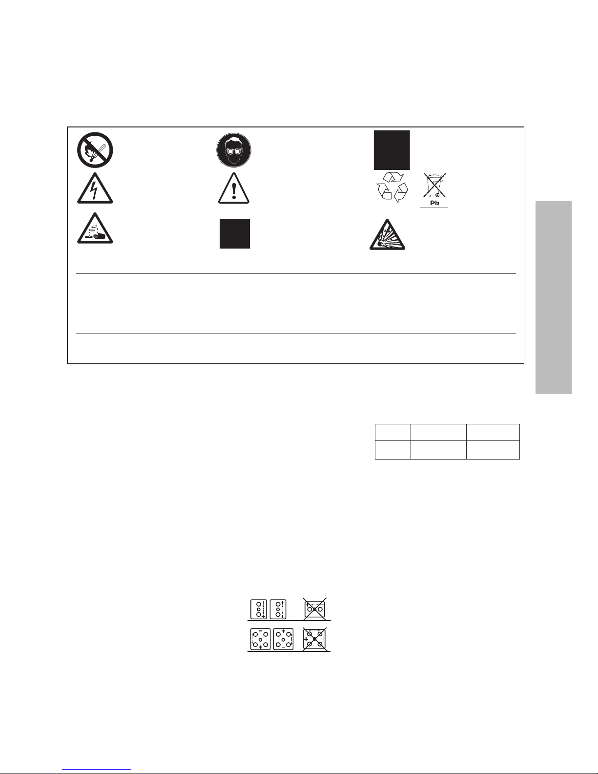
No fumar
Ni llamas vivas
ni chispas
Peligro
d
e electrocución
El electrolito es corrosivo.
Atención a las tapas
y recipientes rotos.
Llevar gafas
de seguridad
Peligro
Aclarar con abundante agua
c
ualquier proyección de ácido
sobre la piel o a los ojos.
Consultar a un médico. La ropa
con ácido debe lavarse con agua.
+
Seguir las instrucciones
de uso
Reciclar los
componentes
de la batería.
C
ontiene plomo.
Aviso : Riesgo de fuego, explosión
o
incendio. No se debe desmontar,
ni calentar por encima de 60ºC,
ni incinerar. Evitar cortocircuitos.
ESPAÑOL
7
Garantía
El no respetar las normas de instalación, utilización y mantenimiento, reparaciones llevadas a cabo con piezas de repuesto no homologadas, una utilización no conforme a las
normas, la adición de productos diversos al electrolito y la interferencia no autorizada con la batería invalidan toda reclamación en concepto de garantía.
Las partes metálicas de la batería tienen tensión.
No dejar herramientas ni ningún tipo de objeto
sobre la batería
RECEPCION Y ALMACENAJE
Controlar toda seal de deterioro o ausencia
de una pieza en el paquete. Almacenar la
batería en un lugar seco, limpio y
preferentemente fresco y protegido de las
heladas. No exponer los elementos
directamente a la luz del sol, ya que ello puede
ocasionar daos en las tapas y recipientes.
Como las baterías se entregan cargadas, el
tiempo de almacenaje es limitado. A fin de
recargar fácilmente las baterías tras un
período prolongado, se aconseja no superar
un tiempo de almacenaje sin recarga de:
6 meses a 20 C
4 meses a 30C
2 meses a 40C
Se realizará entonces una recarga tras este
período o si la tensión del circuito abierto es
inferior a 2,07 V/elemento. El no seguir estas
normas perjudicará la capacidad de la batería
y acortará su vida. La recarga deberá realizarse
según el párrafo a) del apartado “Carga de
puesta en servicio”. De otro modo, los
elementos pueden ser cargados en flotación a
2,25 V/elemento durante el almacenaje.
INSTALACIÓN
No utilice las bornas de conexión para levantar
o manipular los elementos.
Las medidas de protección eléctrica, la
ubicación y la ventilación de la instalación de
la batería serán conformes a las normas y
reglamentos en vigor. Se aplicará
especialmente la norma EN 50272-2. La batería
debe instalarse en un lugar seco y limpio. Al
no desprender gas corrosivo en
funcionamiento normal, puede ser instalada
cerca de cualquier otro material eléctrico. En
condiciones normales, el desprendimiento
gaseoso es muy bajo y una ventilación natural
es suficiente para toda refrigeración y
sobrecarga accidental, permitiendo a las
baterías OPzV ser utilizadas con completa
seguridad tanto en oficinas como en talleres.
Sin embargo, es necesario asegurar una
ventilación adecuada para las baterías
montadas en armarios, las cuales no deberán
ser instaladas dentro de armarios cerrados sin
aberturas de ventilación en las partes superior
e inferior del armario. Evitar colocar la batería
en un lugar caliente o detrás deuna ventana
expuesta al sol. Para una instalación apropiada
se recomiendan las estanterías para baterías.
Colocar los elementos de la batería sobre la
estantería y remitirse al plano para la posición
correcta de las polaridades.
Instalación horizontal
No utilice las bornas de conexión para levantar
o manipular los elementos.
No instalar los elementos de tal forma que la
unión recipiente/tapa esté colocada sobre un
larguero.
Asegúrese siempre de que la flecha en
la tapa de cada elemento seala en la orientación
vertical.
Comprobar que todas las superficies
de contacto están limpias.
Si es necesario, limpiarlas con un cepillo de
latón.
No invierta la posición de los elementos
(conductos de ventilación boca abajo). No
colocarlos de modo que la parte frontal esté mas
baja que la base del elemento ya que se daaría
la válvula de seguridad y podríamos causar daos
irreparables.
Apretar las tuercas utilizando el
par de apriete adecuado (Tabla 1). Para evitar
el deterioro de la materia plástica, no utilizar
grasa. Colocar las fundas de protección contra
el contacto directo.
Tabla 1: Par de apriete de los bulones de
interconexión.
Tipo Tornillo Apriete
OPzV M10 23 – 25 Nm
Seguir la polaridad para evitar cortocircuitosde
los grupos de elementos. Una conexión mal
apretada puede ocasionar problemas para el
reglaje del cargador, un funcionamiento
heterogéneo de la batería y perjudicar a la
batería y/o al personal. Conectar finalmente la
batería a la alimentación en corriente
continua, con el cargador parado, los fusibles
de las baterías retirados y la carga
desconectada. Asegurarse de que la polaridad
es correcta, borna positiva de la batería a
borna positiva del cargador. Conectar el
cargador y la carga remitiéndose al apartado
“Carga de puesta en servicio”. Deberá vigilarse
la primera carga a fin de no superar los límites
y no alcanzar temperaturas inaceptables.
Montaje de los elementos en paralelo
Los elementos OPzV pueden conectarse en
paralelo para proporcionar una capacidad más
elevada. Para este tipo de montaje, utilizar
únicamente baterías de la misma capacidad,
tecnología y antigu edad con un máximo de 4
ramas en paralelo por razones prácticas. La
resistencia de los cables en cada rama debe
ser la misma, es decir, misma sección, misma
longitud. Conectar las ramas en paralelo a las
bornas terminales.
7
Page 9

CARGA DE PUESTA
E
N SERVICIO
Durante la puesta en servicio de una batería
nueva (primera carga), el procedimiento
puede ser el siguiente (procedimiento a)
recomendado):
a) curva IU (carga rápida):
a
tensión aumentada de 2.33 – 2.40 V/elemento.
El tiempo de carga será de 12 a 24 horas en
función de las condiciones de carga inicial.
L
a corriente se limitar á a 4xI
1
0
. L
a carga rápida
puede ser interrumpida o transformada en
carga de flotación cuando se alcance el
estado de carga.
b) carga de flotación:
con una tensión de 2,25 V/elemento. Se
alcanzará la plena capacidad tras un largo
p
eríodo de 4 a 6 semanas en función del
estado de carga.
APLICACION
ESTACIONARIA/TENSION
DE FLOTACION
Tensión de flotación
La tensión de flotación/carga recomendada
es de 2,25 V por elemento a 20ºC
(tolerancia 2,23 – 2,25 V/elemento). La
tensión del cargador es de 2,25 V/elemento
x número de elementos. Cuando la
temperatura media ambiente varíe ± 10ºC
con respecto a la temperatura de
referencia de 20ºC, se recomienda ajustar la
tensión de flotación tal y como sigue:
TemperaturaTensión de flotación
-10 °C 2,37 V/elemento
0 °C 2,33 V/elemento
10 °C 2,29 V/elemento
20 °C 2,25 V/elemento
30 °C 2,23 V/elemento
40 °C 2,21 V/elemento
El ajustamiento no es necesario cuando
la temperatura media de explotación
varie menos que ± 5°C con respecto a
la temperatura de referencia de 20°C.
La tensión de flotación recomendada
es de 2,25 voltios por elemento a 20ºC.
A continuación de la carga de puesta en
servicio y después de 6 meses a la tensión
de flotación recomendada, las tensiones
individuales de los elementos se estabilizarán en una cota de ±4,5% respecto a la
tensión media de la batería. Sin embargo,
inmediatamente después de la puesta en
servicio y durante los 6 primeros meses en
tensión de flotación continua, puede que
se observen valores de tensión individual
por elemento fuera de los límites arriba
mencionados, sin causar efecto desfavorable. No hay relación entre la tensión de
flotación de un elemento y su capacidad
de descarga. Los elementos son perfectamente capaces de suministrar la capacidad
demandada incluso cuando se encuentren
fuera de la cota ±4,5%. Después de 6
meses de servicio, en caso de que la tensión de un elemento estuviera fuera de los
límites anteriormente mencionados
durante más de 3 meses sucesivos, se
debería contactar entonces con el servicio
comercial.
Corriente de carga
La limitación de la corriente de carga de las
baterías no es necesaria para una carga de
flotación inferior a 2,25 V/elemento. Para
tensiones de carga más elevadas, la corriente
de carga se limitará a 0,4 x I
1
0
R
ecarga rápida
P
ara reducir el tiempo de recarga, se puede
recargar la batería a 2,33 - 2,40 V por
elemento con una corriente limitada a 0,4 x
I
1
0
.
La recarga rápida puede pasar a carga
de flotación cuando la batería haya
alcanzado su pleno estado de carga.
Corriente pulsante
E
n aplicación estacionaria, el valor efectivo de
la corriente pulsante alternativa no deberá
superar 5A/100 Ah C
10
, pues de lo contrario
se reducirá la duración de la vida de la batería.
TEMPERATURA
La temperatura recomendada de explotación
está entre -10ºC y +45ºC. La batería ofrecerá
el mejor servicio entre
+1 0°C y +30°C. Temperaturas más elevadas
reducen la duración de su vida. Temperaturas
inferiores reducen la capacidad. Las
temperaturas limites temporales de
funcionamiento no deberán sobrepasar los
–30°C y +55°C condiderando la profundidad de
descarga (bajas temperaturas) y la ventilación
(altas temperaturas). Todos los datos técnicos
se refieren a la temperatura de +20°C. No
exponer los elementos directamente al sol.
DESCARGA
Tensión de fin de descarga
La batería no deberá descargarse más
profundamente que la capacidad
especificada en las tablas de prestaciones.
Descargas más profundas pueden
perjudicar a la batería y acortar su vida. Po r
regla general, la tensión de fin de descarga
debe limitarse a los valores siguientes:
Duración
de la descargaTensión final
1h < t < 5h 1,70 V/elemento
5h < t < 8h 1,75 V/elemento
8h < t < 24h 1,80 V/elemento
Las tensiones individuales no deberán
nunca ser inferiores en más de
0,2 V/elemento respecto a la tensión final.
Se recomienda aplicar un equipo de control
de tensión mínima para evitar la descarga
profunda. Prestar atención a los pequeños
equipos que no se desconectan
automáticamente al final de la descarga.
Elementos descargados
Las baterías OPzV no deben quedar
descargadas después de haber suministrado
una carga, sino que deben ser
inmediatamente recargadas. El no seguir
estas normas puede perjudicar a la vida y
fiabilidad de la batería.
Descarga profunda accidental
La batería debe recargarse a 2,25 V/elemento
seguido de una carga de igualación. Como
al principio la resistencia interna es elevada,
la corriente de carga inicial es baja.
Nota importante:
Toda descarga profunda es abusiva y repercutirá en la duración de la vida de la batería.
TESTS
Se deberán efectuar tests de capacidad según
la norma EN 60896-2. Verificar que la batería
e
stá plenamente cargada. Antes de ensayar
las nuevas baterías, asegurarse de que se ha
efectuado una carga de puesta en servicio
s
uficiente.
Factor de corrección de la temperatura
La temperatura afecta a la capacidad de la
batería. La siguiente tabla muestra el factor
de corrección para una temperatura de
r
eferencia de 20°C.
RECARGA
Después de una descarga, la batería puede ser
recargada a la tensión de explotación (tensión
de carga de flotación). En función de la
profundidad de descarga, esto puede durar
hasta 3 días. A fin de reducir el tiempo de
carga, la recarga se puede efectuar con una
tensión de carga rápida de 2,33 a 2,40
V/elemento. Los tiempos de recarga
dependen de la profundidad de descarga y d e
la corriente de carga disponible; por regla
general, son de 10 a 20 horas para corrientes
de carga entre 5A y 40A por 100Ah C
1
0
. La
carga rápida debe pasar a carga de flotación
cuando se alcance la plena carga.
Carga de igualación
En circunstancias excepcionales únicamente,
es decir, después de descargas profundas o
después de reiteradas recargas inapropiadas,
se podrá llevar a cabo una carga de igualación
según el párrafo a) del apartado “Carga de
puesta en servicio” o con la si guiente curva IU:
Carga a tensión aumentada de 2,33 –
2,40 V/elemento, continuada después con
una corriente constante de 1,5 A por
100 Ah C
10
durante la cual las tensiones de
cada elemento pueden alcanzar 2,60 –
2,65 V/elemento máximo. La carga debe
ser vigilada. El tiempo de carga con corriente
constante deberá ser de 5 a 10 horas.
MANTENIMIENTO
/CONTROLES
Los elementos OPzV son baterías de plomo
ácido sin mantenimiento, estancas y no
necesitan adición de agua.
Las tapas y recipientes deben estar siempre
secos y sin polvo. Limpiar exclusivamente con
un trapo de algodón húmedo sin fibras
sintéticas ni adición de agentes de limpieza.
Evitar la carga electroestática.
Cada 6 meses, verificar la tensión total en las
bornas de la batería, y las tensiones unitarias
de los elementos p iloto y la temperatura. Una
vez al año, efectuar una lectura de la tensión
de los elementos. Llevar un cuaderno de
mantenimiento en el que se anoten los
valores tomados así como los cortes de
electricidad, los tests de descarga, etc.
No abrir la válvula. Su abertura provocaría
el deterioro irreversible de la batería y está
prohibida.
APLICACIONES ESPECIALES
Si la OPzV ha de ser utilizada en aplicaciones
especiales como de ciclaje repetido o en
condiciones ambientales extremas, contacten
con su SERVICIO COMERCIAL.
Para más información, consulten nuestra
página web www.enersys-emea.com
8
D
uración temperatura en °C
d
e descarga -100+10 +20 +30 +40
5-12 horas 0.60 0.78 0.90 1.00 1.05 1.07
1-4 horas 0.55 0.74 0.88 1.00 1.06 1.08
8
Se deberán efectuar tests de capacidad segú n
la norma EN 60896-21/22. Verificar que la
batería está plenamente cargada. Antes de
ensayar las nuevas baterías, asegurarse de que
se ha efectuado una carga de puesta en
s
ervicio suficiente.
Page 10

Notes :
Page 11

Page 12

Publication No. EN-zV-OM-004 - Ref DCE1010M/06-2013 - Subject to revisions without prior notice. E.&O.E.
www.enersys-emea.com
Contact:
EnerSys Asia
152 Beach Road
Gateway East Building
Level 11
189721 Singapore
Tel: +65 6508 1780
© 2013 EnerSys®. All rights reserved.
Trademarks and logos are the property of
EnerSys
®
and its affiliates unless otherwise noted.
EnerSys EMEA
EH Europe GmbH
Löwenstrasse 32
8001 Zurich
Switzerland
EnerSys
2366 Bernville Road
Reading, PA 19605
USA
Tel: +1-610-208-1991
+1-800-538-3627
Fax: +1-610-372-8613
 Loading...