

Page 1
BATTERY
TM
RESERVE
POWER
APPLICATION MANUAL
Genesis®NP and NPX
Series
Page 2
TM
Genesis®NP & NPX Battery Series Application Manual
Table of contents
Introduction 2
Technical Features 3
Applications 4
Battery Construction 4
Today’s Genesis®NP Battety series is
the culmination of more than ten
decades of battery manufacturing
experience. High energy density,
leak proof construction, excellent
performance in either float or
cyclic applications and long
service life combine to make the
Genesis NP Series the most
reliable and versatile maintenance
free rechargeable sealed lead acid
batteries available.
General Specifications NP Series 5
Range Summary Layout Terminal Configurations 6
Battery Capacity Selection Charts 7
Discharge 7-9
Discharge Characteristics
Temperature Characteristics
Over-Discharge (Deep Discharge)
Storage, Self-Discharge, and Shelf Life 9
Self-Discharge
Shelf Life
Recharging Stored Batteries
Ohmic Readings 9
Charging 10-13
Constant Current Charging
Two Step Constant Voltage Charging
Charging Voltage
Initial Charge Current Limit
Refresh Charging
Temperature Compensation
Charging Efficiency
Solar Powered Charging
2 www.enersys.com
Service Life of Genesis®NP Batteries 13
Cyclic Service Life
Float Service Life
Tips & Precautions 14
Glossary 14-15
Limited Warranty 16
Publication No: US-NP-AM-003 • January 2011
Page 3

Technical Features Benefit
TM
Construction
Electrolyte Suspension System
Gas Generation
Maintenance Free Operation
Low Pressure Valve Regulated System
The construction and sealing techniques of the Genesis NP
battery guarantees leakproof operation in any position
except inverted, with no adverse effect to capacity or
service life.
All Genesis®NP batteries utilize an electrolyte suspension
system consisting of a high porosity, glass fiber material
which in conjunction with plates, totally absorb and
contain the electrolyte. No silica gels or any other
contaminants are used.
Genesis NP batteries incorporate a built-in design that
controls gas generation and induces recombination of
more than 99% of gases generated during float usage.
There is no need to check specific gravity of the electrolyte
or add water to Genesis NP batteries during float service
life. In fact, there is no provision for this type of
maintenance.
All Genesis NP batteries are equipped with safety release
valves, designed to operate between 2 and 5 psi and
automatically reseal. Hence, there is never an excessive
accumulation of gas within the battery.
Heavy Duty Grids
Cyclic Service Life
Float Service Life
Self Discharge - Shelf Life
Operating Temperature
Deep Discharge Recovery
www.enersys.com
Heavy duty lead calcium tin alloy grids provide an extra
margin of performance and service life in either float or
cyclic applications, even after repeated over discharges.
More than 1000 discharge/recharge cycles can be realized
from Genesis NP batteries, dependent on the average
depth of discharge.
Genesis NP Series batteries have an expected life span of
3 to 5 years in float service applications.
The self discharge rate of the Genesis NP series at room
temperature is approximately 3% of rated capacity per
month.
Genesis NP Batteries may be operated over a broad range
of ambient temperatures.
Genesis NP batteries recover their capacities even after
repeated deep discharges.
Publication No: US-NP-AM-003 • January 2011 3
Page 4
Applications
NP7-12 12V, 7.0Ah
SEALED RECHARGEABLE LEAD-ACID BATTERY
CAUTION:
• DO NOT SHORT OR PUT IN FIRE. MAY EXPLODE OR LEAK.
• USE APPROVED CHARGING METHODS.
• SHORT CIRCUIT PROTECTION REQUIRED DURING TRANSPORTATION.
• DO NOT CHARGE IN A SEALED CONTAINER.
• BATTERYPOSTS, TERMINALS, AND RELATED ACCESSORIES CONTAIN LEAD
AND LEAD COMPOUNDS, CHEMICALS KNOWN TO THE STATEOF CALIFORNIA
TO CAUSE CANCER AND REPRODUCTIVE HARM. BATTERIES ALSO CONTAIN OTHER
CHEMICALS KNOWN TO THE STATEOF CALIFORNIA TO CAUSE CANCER.
WASH HANDS AFTER HANDLING.
READING, PA 19612MADE IN VIETNAM
ENERSYS
NON-SPILLABLE
www.enersys.com
MH16464
NP712GNV
A partial list of common applications include:
Burglar and Fire Alarm
Office Machines
Cash Registers
Solar Power Devices
Telecommunications
Uninterruptable Power Supply (UPS) Equipment
Emergency Lighting
Computers
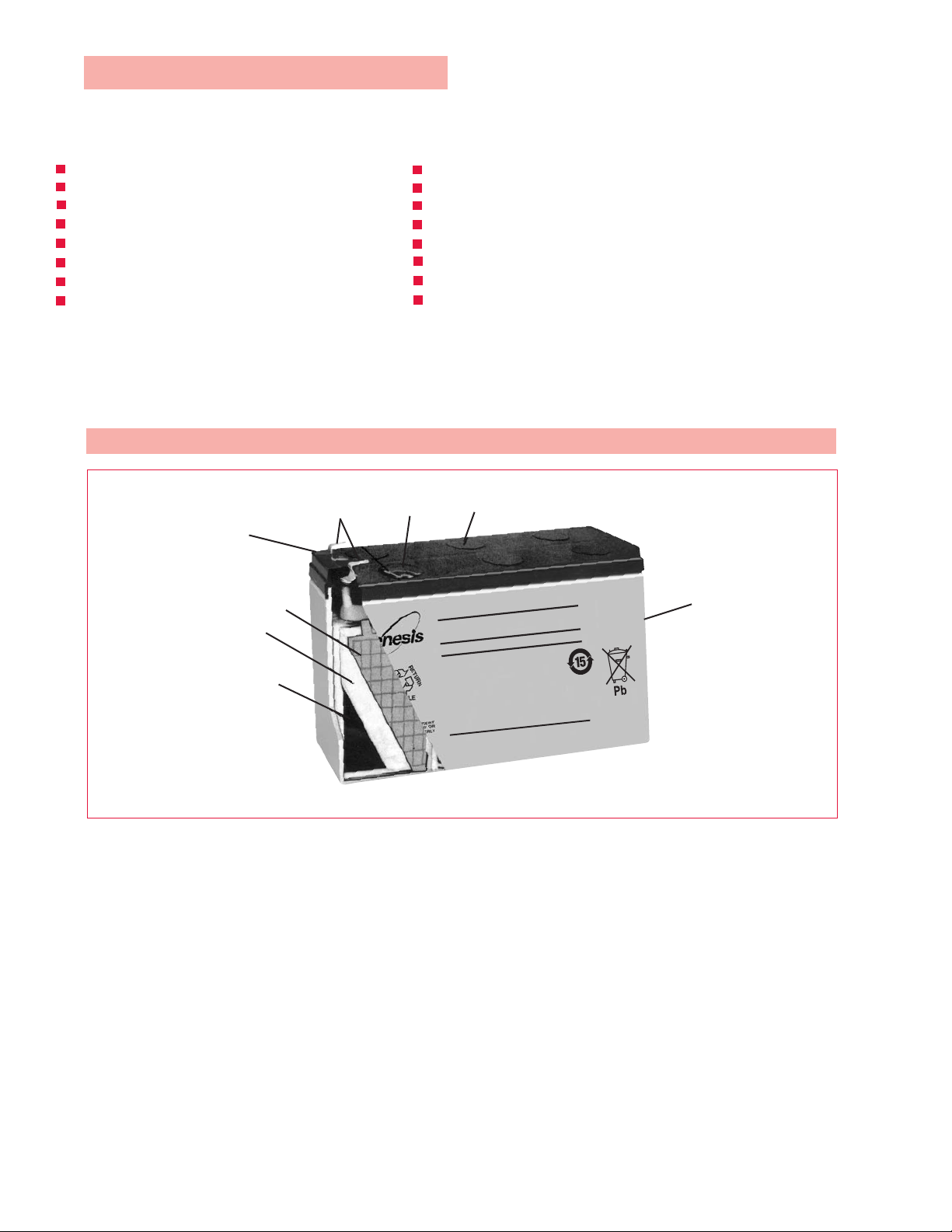
Genesis NP Battery Construction
Terminal
Sealant
Negative Plate
Absorbant
Glass
Mat
Positive Plate
Relief Valve
Audio and Video Equipment
Portable Lights
Electric Wheelchairs
Test Equipment
Geophysical Equipment
Power Tools
Surveillance Systems
Dispensing Machines
Lid
Container
NOTE:
Not recommended for use in medical equipment or devices
Not recommended for use in inverted “vents down” position
4 www.enersys.com
Publication No: US-NP-AM-003 • January 2011
Page 5

General Specifications Genesis®NP Battery Series
GENESIS®NP BATTERY SERIES
Battery
Type FR Type* Volts Capacity Length Width Incl. Terminals Layout Terminals
NP1-6 NP1-6FR 1.0 51.0 2.01 42.0 1.65 57.0 2.24 0.28 0.61 5A
NP1.2-6 NP1.2-6FR 1.2 97.0 3.82 25.0 0.98 56.0 2.20 0.30 0.67 1A
NP2.8-6 NP2.8-6FR 2.8 67.0 2.64 33.0 1.30 105.0 4.13 0.59 1.30 5 A/C
NP3-6 NP3-6FR 3.0 134.0 5.28 33.0 1.30 67.0 2.64 0.69 1.53 1A
NP3.2-6 NP3.2-6FR 3.2 66.0 2.60 33.0 1.30 104.0 4.09 0.59 1.30 5A
NP3.8-6 NP3.8-6FR 3.8 66.0 2.60 33.0 1.30 125.0 4.92 0.75 1.65 1A
NP4-6 NP4-6FR 6 4.0 70.0 2.76 47.0 1.85 105.0 4.15 0.80 1.76 5 A/C
NP4.5-6 NP4.5-6FR 4.5 70.0 2.76 47.0 1.85 105.0 4.15 0.86 1.90 5 A/C
NP5-6 NP5-6FR 5.0 70.0 2.76 47.0 1.85 105.0 4.15 0.95 2.10 5 A/C
NP7-6 NP7-6FR 7.0 151.0 5.95 33.0 1.30 100.0 3.94 1.28 2.83 1 A/C
NP8.5-6 NP8.5-6FR 8.5 98.0 3.86 56.0 2.20 118.0 4.65 1.60 3.53 9 A/C
NP10-6 NP10-6FR 10.0 151.0 5.95 50.0 1.97 101.0 3.98 1.99 4.38 1 A/C
NP12-6 NP12-6FR 12.0 151.0 5.95 50.0 1.97 101.0 3.98 2.04 4.48 1 A/C
NP0.8-12 NP0.8-12FR 0.8 96.0 3.78 25.0 0.98 61.0 2.42 0.37 0.82 7 H/I
NP1.2-12 NP1.2-12FR 1.2 97.0 3.82 48.0 1.89 56.0 2.20 0.57 1.25 3A
NP2-12 NP2-12FR 2.0 150.0 5.91 20.0 0.79 89.0 3.50 0.70 1.54 8B
NP2-12-C NP2-12-CFR 2.0 182.0 7.17 24.0 0.93 61.0 2.40 0.73 1.61 6L
NP2.3-12 NP2.3-12FR 2.3 178.0 7.01 35.0 1.38 67.0 2.64 1.02 2.15 1A
NP2.6-12 NP2.6-12FR 2.6 134.0 5.28 67.0 2.64 66.0 2.60 1.36 3.00 3A
NP2.9-12 NP2.9-12FR 2.9 79.0 3.11 56.0 2.20 105.0 4.13 1.24 2.73 1 A/C
NP3-12 NP3-12FR 3.0 132.0 5.20 33.0 1.30 105.0 4.13 1.18 2.60 1 A/C
NP3.4-12 NP3.4-12FR 3.4 134.0 5.28 67.0 2.64 67.0 2.64 1.39 3.06 3 A/C
NP4-12 NP4-12FR 4.0 90.0 3.54 70.0 2.76 107.0 4.21 1.70 3.74 1 A/C
NP4.5-12 NP4.5-12FR 4.5 90.0 3.54 70.0 2.76 107.0 4.21 1.76 3.88 1 A/C
NP5-12 NP5-12FR 5.0 90.0 3.54 70.0 2.76 107.0 4.21 1.81 4.00 1 A/C
NP7-12 NP7-12FR 7.0 151.0 5.95 65.0 2.56 100.0 3.94 2.59 5.72 4 A/C
NP12-12 NP12-12FR 12 12.0 151.0 5.95 98.0 3.86 100.0 3.94 4.06 8.95 4C
NP18-12 NP18-12FR 17.2 181.0 7.13 76.0 3.00 167.0 6.57 6.17 13.60 2 D/E
NP24-12 NP24-12FR 24.0 166.0 6.54 175.0 6.89 125.0 4.92 9.07 20.00 2 C/D/E
NP33-12 NP33-12FR 33.0 197.0 7.76 131.0 5.16 158.0* 6.22* 11.79 26.00 1 E/F
NP-35-12 NP-35-12FR 35.0 198.0 7.80 132.0 5.20 170.0 6.69 12.61 27.80 1F
NP38-12 NP38-12B 38.0 197.0 7.76 165.0 6.50 172.0 6.77 14.59 32.16 2 F/G
NP55-12 NP55-12FR 56.3 229.0 9.02 138.0 5.43 207.0
NP65-12 NP65-12FR 65.0 350.0 13.78 166.0 6.54 174.0 6.85 23.63 52.10 2 F/G
NP75-12 NP75-12FR 77.5 259.0 10.20 169.0 6.65 208.0
NP90-12 NP90-12FR 90.0 304.0 11.97 168.0 6.61 229.0 9.02
NP100-12 NP100-12FR 100.0 329.0 12.95 174.0 6.85 214.0
NP120-12 NP120-12FR 120.0 407.0 16.02 173.0 6.81 235.0 9.25 38.41 84.68 1 J/G
NP150-12 NP150-12FR 150.0 483.0 19.02 170.0 6.69 241.0 9.49 47.13 103.90 1 J/G
NP200-12 NP200-12FR 200.0 520.0 20.47 260.0 10.24 208.0 8.19 73.00 160.93 3 K/G
Nominal Overall Height
(20 hr rate - Ah)
mm. (in.) mm (in.) mm. (in.) kgs. (lbs.)
†
†
†
Weight
8.15†18.01 39.70 1 M/E
8.19†26.50 58.42 1 M/G
†
31.18 68.74 1 M/G
8.43†32.94 72.62 1 J/G
DATASAFE®NPX BATTERY SERIES
Battery W/Cell to 1.67 Nominal Overall Height
Type FR Type* Volts End Voltage Capacity Length Width Incl. Terminals Layout Terminals
NPX-35-6 NPX-35-6FR 35W/Cell 8 151.0 5.95 33.0 1.30 100.0 3.94 1.43 3.15 1 A/C
NPX-50 NPX-50FR 50W/Cell 13 151.0 5.95 50.0 1.97 100.0 3.94 2.09 4.60 1 A/C
NPX-25 NPX-25FR 23W/Cell 5 90.0 3.54 70.0 2.75 107.0 4.21 1.95 4.30 1 A/C
NPX-35 NPX-35FR 35W/Cell 8 151.0 5.95 65.0 2.56 100.0 3.94 2.75 6.06 4 A/C
NPX-80 NPX-80FR 80W/Cell 20 181.0 7.13 76.0 2.39 167.0 6.57 6.35 14.0 2 D/E
NPX-100 NPX-100FR 95W/Cell 28 166.0 6.54 125.0 4.92 175.0 6.89 9.70 21.38 2 D/E
NPX-135 NPX-135FR 135W/Cell 33 197.0 7.76 131.0 5.16 158.0†6.22 11.94 26.32 1 E/F
NPX-150 NPX-150FR 150W/Cell 40 197.0 7.76 165.0 6.50 172.0 6.77 14.29 31.50 2 F/G
FOOTNOTES:
* FR: UL94-VO, Flame Retardant Case and Cover (Oxygen index: 28)
† Height is to top cover. Overall height, including terminal is dependent on terminal configuration.
Recognized by UL File No. MH16464
NOTE: All dimensions are +/- 0.08 inches (2mm); Weights are +/- 5%
www.enersys.com
6
12
(15 Min Rate)
Weight
(20hr rate - aH) mm. (in.) mm (in.) mm. (in.) kgs. (lbs.)
TORQUE SPECIFICATIONS:
M5 Bolt: 26.6 lbf.in (3Nm) +/- 5%
M6 Bolt: 44.31 lbf.in (5Nm) +/- 5%
M5 receptacle: 35.4 lbf.in (4Nm) +/- 5%
M6 receptacle: 65 lbf.in (6.8Nm) +/- 5%
Publication No: US-NP-AM-003 • January 2011 5
Page 6

Range Summary
• LAYOUT
• TERMINAL
Faston Tab: 187
M5Threaded Receptacle
Tyco. 1-480318-0
INCH = MM INCH = MM
Faston Tab: 187
INCH = MM
M6 Bolt Fastened Terminal
INCH = MM
M8 Bolt Fastened Terminal
INCH = MM
INCH = MM
Faston Tab: 250
M6 Threaded Receptacle
M10 Bolt Fastened Terminal
INCH = MM
INCH = MM
INCH = MM
M5 Bolt Fastened Terminal
INCH = MM
JST No. VHR-2N
INCH = MM
“Camcorder” Terminal
M8 “Universal” Bolt Fastened Terminal
Terminal Continuous 1Hr. 1 Min.
Faston tab 187 16 24 48
Faston tab 250 25 38 75
Wire Lead 0.5mm^2 7 20 30
All Bolt or Receptacle 6CA
Maximum Permissable Current (Amps)
Charging
•
Standby use: Apply constant voltage charging at 2.275 volts
per cell (or 2.25–2.30VPC).
•
Cyclic use: Apply constant voltage charging at 2.40-2.50 VPC.
Initial charging current should be set at less than 0.25CA.
•
Top charge: Product in storage (ambient temperature 25°C/77°F)
requires a top charge every six months. Apply constant voltage at
2.40 volts per cell, initial charging current should be set at
less than 0.1CA for 15 to 20 hours.
Discharge
•
Stop operation when voltage has reached the minimum
permissible voltage. Recharge immediately.
•
Do not operate above 6CA or more current continuously.
6 www.enersys.com
Storage
•
Always store battery in a fully charged condition.
•
If battery is to be stored for a long period, apply a recovery
top-charge every 6 months.
•
Store batteries in a dry and cool location.
Temperature
•
Keep within ambient temperatures of –150C to +500C for both
charging and discharging.
Incorporating battery into equipment
•
Install battery in a well ventilated compartment.
•
Avoid installing battery near heated units such as a transformer.
•
House the battery in the lowest section of the equipment
enclosure or rack to prevent unnecessary battery temperature
rise.
Others
•
Avoid terminal short circuit.
•
Avoid exposure of the ABS container and cover material to PVC-based
rubber mats or spacers
•
DO NOT expose to open flame
•
WARNING - Avoid exposure of the battery to any type of
oil, solvent, detergent, petroleum-based solvent or ammonia
solution. These materials could potentially cause permanent
damage to the battery jar and cover and will void the warranty.
.
Publication No: US-NP-AM-003 • January 2011
Page 7

DISCHARGE CURRENT
MINUTES
HOURS
AT 25ºC (77ºF)
Battery Capacity Selection
Discharge
Figure 1 may be used to determine battery size (expressed in
Ampere Hours of capacity), for a specific application. To
determine the capacity of the battery, establish the discharge
current for the length of discharge time required. The point
where the current and time lines intersect is the minimum
capacity battery needed for the application. It is recommended
you also refer to Figures 3 before making your final decision.
Figure 2 is the high rate capacity selection chart for Genesis
NPX series batteries. These batteries are typically used for UPS
constant power applications under 30 minutes.
Figure 1. 20-Hour Rate Capacity Selection Chart
Discharge Characteristics
The curves shown in Figure 1, and the discharge rates shown
in Table 3 illustrate the typical discharge characteristics of
Genesis NP batteries at an ambient temperature of 25˚C
(77˚F). The symbol “C” expresses the nominal capacity of the
Genesis NP battery, measured at a 20 hour discharge rate.
®
Please refer to General Specifications to determine the
nominal capacity rating of the specific model.
The industry standard for designating the nominal capacity of
a sealed lead acid battery involves a discharge test for a given
number of hours to a final pre-set end voltage. The average
current value multiplied by the hours of discharge time
determines the capacity rating of that particular battery.
Since manufacturers vary in their rating standards, it is
always a good practice to question the rating standard.
Table 1 shows how the rated nominal capacity
decreases when the discharge load is higher than the 20
hour rate. This table should be consulted when selecting
a battery for a high discharge application.
The discharge rates depicted in Figure 2 and Table 2
reference watts per cell of the DataSafe
®
NPX series of
batteries. These batteries are designed for Uninterruptable
Power Supply (UPS) applications where high rate discharge
performance (under 30 minutes) is typical. To determine the
battery kilowatt rating required for a UPS system, refer to the
following formula: KVA rating of UPS x Power Factor (Pf)
÷ inverter efficientcy = Total Battery Kilowatts (KWB)
Temperature characteristics
At higher temperatures, the electrical capacity that can be
taken out of a battery increases. At lower temperatures, the
electrical capacity that can be taken out of a battery
decreases. Figure 4 shows the temperature effects in relation
to battery capacity.
Discharge Constant Power Watts/Cell
Figure 2. High Rate Discharge Capacity Selection Chart
Figure 4. Temperature Effects in Relation to Battery Capacity
Figure 3. Discharge Characteristic Curves: Genesis®NP Batteries
www.enersys.com
Publication No: US-NP-AM-003 • January 2011 7
Page 8

Discharge Capacity
20 Hr 10 Hr 5 Hr 3 Hr 1 Hr
NP0.8-12
0.8 0.8 0.74 0.68 0.62 0.48
NP1-6 1.0 1.0 0.93 0.85 0.78 0.60
NP1.2-6,NP1.2-12 1.2 1.2 1.1 1.0 0.9 0.7
NP2-12 2.0 2.0 1.9 1.7 1.6 1.2
NP2.3-12 2.3 2.3 2.2 2.0 1.8 1.4
NP2.6-12 2.6 2.6 2.4 2.2 2.0 1.6
NP2.8-6 2.8 2.8 2.6 2.4 2.2 1.7
NP2.9-12 2.9 2.9 2.7 2.5 2.3 1.7
NP3-6,NP3-12 3.0 3.0 2.8 2.6 2.3 1.8
NP3.2-6 3.2 3.2 3.0 2.7 2.5 1.9
NP3.4-12 3.4 3.4 3.2 2.9 2.7 2.0
NP3.8-6 3.8 3.8 3.5 3.2 3.0 2.3
NP4-6,NP4-12 4.0 4.0 3.7 3.4 3.1 2.4
NP4.5-6,NP4.5-12 4.5 4.5 4.2 3.8 3.5 2.7
NP5-6,NP5-12 5.0 5.0 4.6 4.3 3.8 3.0
NP7-6,NP7-12 7.0 7.0 6.5 6.0 5.4 4.2
NP8.5-6 8.5 8.5 7.9 7.2 6.6 5.1
NP10-6 10.0 10.0 9.3 8.5 7.7 6.0
NP12-6,NP12-12 12.0 12.0 11.2 10.2 9.2 7.2
NP18-12 17.2 17.2 16.0 14.6 13.2 10.3
NP24-12 24.0 24.0 22.3 20.4 18.5 14.4
NP33-12 33.0 33.0 30.7 28.1 25.7 19.8
NP35-12 35.0 35.0 32.6 29.8 27.3 21.0
NP38-12 38.0 38.0 35.0 32.3 29.3 22.8
NP55-12 55.0 55.0 49.5 46.8 42.9 33.0
NP65-12 65.0 65.0 60.5 55.3 50.1 39.0
NP75-12 75.0 75.0 69.8 63.8 58.5 45.0
NP90-12 90.0 90.0 83.7 76.5 70.2 54.0
NP100-12 100.0 100.0 93.0 85.0 78.0 60.0
NP120-12 120.0 120.0 111.6 102.0 93.6 72.0
NP150-12 150.0 150.0 139.5 127.5 117.0 90.0
NP200-12 200.0 200.0 186.0 170.0 156.0 120.0
20 Hr.
Cap.
(Ah)
(Ah)
0.05CA to 1.75 V/C 0.093CA to 1.75 V/C 0.17CA to 1.70 V/C 0.26CA to 1.67 V/C 0.60CA to 1.60 V/C
Type
Genesis
®
NP Battery
5 Min 10 Min 15 Min 20 Min 30 Min
NPX-25 47.0 31.0 23.0 18.8 13.8
NPX-35/NPX-35-6 68.0 44.0 35.0 28.0 21.5
NPX-50 94.0 67.0 50.0 39.0 30.0
NPX-80 155.0 104.0 80.0 65.0 42.0
NPX-100 185.0 125.0 95.0 75.0 55.0
NPX-150 285.0 200.0 150.0 120.0 90.0
Type
Genesis
®
NP Battery
0.05C 0.1C 0.2C 0.4C 0.6C 1C 2C 3C
NP0.8-12
0.8 A 0.04 0.08 0.16 0.32 0.48 0.8 1.6 2.4
NP1-6 1.0 0.05 0.10 0.20 0.40 0.60 1.0 2.0 3.0
NP1.2-12,NP1.2-6 1.2 0.06 0.12 0.24 0.48 0.72 1.2 2.4 3.6
NP2-12 2.0 0.10 0.20 0.40 0.80 1.20 2.0 4.0 6.0
NP2.3-12 2.3 0.12 0.23 0.46 0.92 1.38 2.3 4.6 6.9
NP2.6-12 2.6 0.13 0.26 0.52 1.04 1.56 2.6 5.2 7.8
NP2.8-6 2.8 0.14 0.28 0.56 1.12 1.68 2.8 5.6 8.4
NP2.9-12 2.9 0.15 0.29 0.58 1.16 1.74 2.9 5.8 8.7
NP3-6,NP3-12 3.0 0.15 0.30 0.60 1.20 1.80 3.0 6.0 9.0
NP3.2-6 3.2 0.16 0.32 0.64 1.28 1.92 3.2 6.4 9.6
NP3.4-12 3.4 0.17 0.34 0.68 1.36 2.04 3.4 6.8 10.2
NP3.8-6 3.8 0.19 0.38 0.76 1.52 2.28 3.8 7.6 11.4
NP4-6,NP4-12 4.0 0.20 0.40 0.80 1.60 2.40 4.0 8.0 12.0
NP4.5-6,NP4.5-12 4.5 0.23 0.45 0.90 1.80 2.70 4.5 9.0 13.5
NP5-6,NP5-12 5.0 0.25 0.50 1.00 2.00 3.00 5.0 10.0 15.0
NP7-6,NP7-12 7.0 0.35 0.70 1.40 2.80 4.20 7.0 14.0 21.0
NP8.5-6 8.5 0.43 0.85 1.70 3.40 5.10 8.5 17.0 25.5
NP10-6 10.0 0.50 1.00 2.00 4.00 6.00 10.0 20.0 30.0
NP12-6,NP12-12 12.0 0.60 1.20 2.40 4.80 7.20 12.0 24.0 36.0
NP18-12 17.2 0.86 1.72 3.44 6.88 10.32 17.2 34.4 51.6
NP24-12 24.0 1.20 2.40 4.80 9.60 14.40 24.0 48.0 72.0
NP33-12 33.0 1.65 3.30 6.60 13.20 19.80 33.0 66.0 99.0
NP35-12 35.0 1.75 3.50 7.00 14.00 21.00 35.0 70.0 105.0
NP38-12 38.0 1.90 3.80 7.60 15.20 22.80 38.0 76.0 114.0
NP55-12 55.0 2.75 5.50 11.00 22.00 33.00 55.0 110.0 165.0
NP65-12 65.0 3.25 6.50 13.00 26.00 39.00 65.0 130.0 195.0
NP75-12 75.0 3.75 7.50 15.00 30.00 45.00 75.0 150.0 225.0
NP90-12 90.0 4.50 9.00 18.00 36.00 54.00 90.0 180.0 270.0
NP100-12 100.0 5.00 10.00 20.00 40.00 60.00 100.0 200.0 300.0
NP120-12 120.0 6.00 12.00 24.00 48.00 72.00 120.0 240.0 360.0
NP150-12 150.0 7.50 15.00 30.00 60.00 90.00 150.0 300.0 450.0
NP200-12 200.0 10.00 20.00 40.00 80.00 120.00 200.0 400.0 600.0
20 Hr.
Cap.
(A)
Discharge Current (A)
Type
Genesis
®
NP Battery
Table 1. Discharge Current at Stipulated Discharge Rates
Table 2. NPX Watts Per Cell to 1.67 End Voltage
Table 3. Discharge Capacity at Various Discharge Rates
8 www.enersys.com
Publication No: US-NP-AM-003 • January 2011
Page 9

Over-Discharge (Deep Discharge)
The dotted line in Figure 3 indicates the lowest
recommended voltage under load, or cut-off voltage, at
various discharge rates. In general, lead acid batteries are
damaged in terms of capacity and service life if discharged
below the recommended cut-off voltages. It is generally
recognized that all lead calcium alloy grid batteries are subject
to over-discharge damage. For example, if a lead acid battery
were discharged to zero and left in either open or closed
circuit for a long period of time, severe sulfation and shorting
would occur, thus raising the internal resistance abnormally
high. In such an extreme case, the battery may not accept a
charge.
®
Genesis
NP Series batteries however, have been designed to
withstand such occasional over discharge. While it is not
recommended, Genesis NP batteries can recover their full
capacity under normal charging conditions, even when they
have been subjected to extreme over discharge.
Final discharge voltage is as shown in Table 4.
Table 4. Final Discharge Voltage
Discharge Current Final Discharge (V/Cell)
0.1C or below, or Intermittent discharge 1.75
0.17C or current close to it 1.70
0.26C or current close to it 1.67
0.6C or current close to it 1.60
From 0.6C to 3C 1.45
Current in excess of 3C 1.30
at temperatures higher than the ranges recommended, will
have no adverse effect on storage time or service life.
However, if such use continues for more than one month, the
storage time must be determined according to the new
ambient temperature.
Table 5 below shows the normal storage time or shelf life at
various ambient temperatures. Figure 6 shows open circuit
voltage vs. state of charge.
Table 5. Shelf Life at Various Temperatures
Temperature
00C ( 320F) to 200C ( 680F)
210C ( 700F) to 300C ( 860F)
310C ( 880F) to 400C (1040F)
410C (1060F) to 500C (1220F)
Shelf Life
12 months
9 months
5 months
2.5 months
When considering discharge currents exceeding 6C, consult
with an EnerSys Application Engineer.
Storage, Self-Discharge and Shelf Life
Self-Discharge
The self-discharge rate of Genesis NP batteries is approximately 3% per month when the storage temperature is
maintained at 20
with storage temperature and the remaining capacity. The
relationship between storage times at various temperatures
and remaining capacity is shown in Figure 5.
REMAINING CAPACITY
Figure 5. Self Discharge Characteristics
Shelf Life
In general, when lead acid batteries of any type are stored in a
discharged condition for extended periods of time, lead
sulfate is formed on the negative plates of the batteries. This
phenomenon is referred to as “sulfation”. Since the lead
sulfate acts as an insulator, it has a direct detrimental effect
on charge acceptance. The more advanced the sulfation, the
lower the charge acceptance. “Brief storage”, ie., a few days,
www.enersys.com
Figure 6. Open Circuit Voltage vs. State of Charge
Recharging Stored Batteries
In general, to optimize performance and service life, it is
recommended that Genesis NP batteries which are to be
stored for extended periods of time be given a supplementary
charge, commonly referred to as a “refresh charge”,
periodically. Please refer to the recommendations listed
under REFRESH CHARGING in this manual.
0
C (680F). The self-discharge rate will vary
(%)
200C
STORAGE TIME (MONTHS)
Ohmic Readings
Instruments exist from various manufacturing companies to
determine internal Ohmic measurements of cells such as
internal impedance and conductance that could be used to
assess the health of VRLA batteries. The internal impedance
(resistance) of a battery is lowest when the battery is in a fully
charged state. The internal impedance increases gradually
during discharge. Conductance is the inverse of impedance
which is measured in MHOS, also known as Siemens. The
internal Ohmic measurements of a battery consists of a
number of factors, including, but not limited to, the
temperature and state of charge of the battery, the physical
connection resistances, the ionic conductivity of the
electrolyte, and the activity of electrochemical processes
occurring at the plate surfaces. It should be understood that
neither conductance nor impedance are perfect predictors of
battery capacity.
The correct way to use ohmic readings is as a trending tool
over time to detect potentially weak or troublesome cells of a
VRLA battery string in float service. For ohmic measures that
are trended over time, insight can be provided into the
expected life of a cell. The user should establish a baseline
value for each block at the time of installation. Throughout
the battery's life, the ohmic readings should be compared
against this baseline. The most accurate health indicator is to
establish a baseline for each individual block at the time of
installation and periodically monitor ohmic readings.
Publication No: US-NP-AM-003 • January 2011
9
Page 10

Charging
Proper charging is one of the most important factors to
consider when using maintenance free sealed lead-acid
batteries. Battery performance and service life will be directly
affected by the efficiency of the charger selected. The two
charging methods are:
Constant Current Charging
Two Step Constant-Voltage Charging
Constant Current Charging
This charging method is not often utilized for sealed lead- acid
batteries, but is an effective method for charging a multiple
number of batteries at one time, and/or as an equalizing
charge to correct variances in capacity between batteries in a
group. Caution should be exercised when charging by
constant current. If the charge is continued at the same rate
for an extended period of time after the battery has reached a
fully charged state, severe overcharge may occur, resulting in
damage to the battery.
Two Step Constant Voltage Charging
Two step constant voltage charging is the recommended
method for charging a sealed lead-acid battery in a short
period of time, and maintaining the battery in a fully charged
standby or float condition,thereafter. Figure 7 illustrates the
characteristics of a two step constant voltage charger.
Figure 7. Charging Characteristics of a Two Step Constant-Voltage
The characteristics shown in Figure 7 are those of a constant
voltage, constant current charger. In the initial charging
stage, the battery is charged by constant current. The
charging voltage rises, as the charge continues, until it
reaches 2.45 volts per cell, at which point the charging mode
automatically changes to constant voltage charging. During
the constant current charging stage (A-B) the charging current
which has decreased to point B is sensed, and the charging
voltage is switched to the float level of 2.3 volts per cell from
the recovery level of 2.45 volts per cell. The switch to
constant voltage trickle charging occurs after the battery has
recovered approximately 80% of the rated capacity over a
given period of time. This charging method is one of the most
efficient. The recharge time is minimized during the initial
charging stage while the battery is protected from overcharge
by the system switching over to float charge at the switching
point B.
Charger
10 www.enersys.com
Publication No: US-NP-AM-003 • January 2011
Page 11

Charging Voltage
The charging voltage should be regulated according to the
type of service in which the battery will be used. Generally,
the following voltages are used at 25˚C (77˚F).
For standby (float) use . . . . . . . 2.25 to 2.30 volts per cell
For cyclic use . . . . . . . . . . . . . 2.35 to 2.45 volts per cell
In a constant voltage charging system, a large amount of
current will flow during the initial stage of charging, and
decrease as the charging progresses. When charging at 2.30
volts per cell, charging current at the final stage of charging
will drop to as little as 0.002CA.
Refresh Charging
Since any battery loses capacity through self-discharge, it is
recommended that “refresh charging” be applied to any battery which has been stored for a long period of time, prior to
putting the battery into service. Excepting conditions in which
storage temperatures have been abnormally high, refresh
charging is recommended within the following
parameters:
Battery Age Refresh Charging Recommendations
Charging voltage should be regulated in relation to the
ambient temperature. When the temperature is higher, the
charging voltage should be lower. When the temperature is
lower, the charging voltage should be higher. For specific
recommendations, please refer to the section on Temperature
Compensation. Similarly, capacity (measured in amperehours) attainable over time will vary in direct relation to the
ambient temperature. The capacity in a given period of time
will be larger at higher temperatures, and smaller at lower
temperatures.
Initial Charge Current Limit
A discharged battery will accept a high charging current at the
initial stage of charging. High charging current can cause
abnormal internal heating which may damage the battery.
Therefore, it is recommended that the charging current be
normally limited to 0.25CA. However, in standby use, Genesis
NP batteries are designed so that even if the charging current
is higher than the recommended limit, they will not accept
more than 2CA, and the charging current will be reduced to a
relatively small value in a very brief period of time. Therefore,
in standby use, no current limit is required.
It is recommended that a current limiting function be provided
in the charger in order to prevent charger failure due to overheating of the transformer, or other damage resulting from
mishandling, i.e., short circuiting or reversing polarity.
Within 6 months
after manufacture
Within 12 months
after manufacture
4 to 6 hours at constant current of 0.1CA, or 15 to 20
hours at constant voltage of 2.40 volts per cell.
8 to 10 hours at constant current of 0.1CA, or 20 to 24
hours at constant voltage of 2.40 volts per cell.
Genesis NP batteries must not be allowed to self-discharge to
less than 2.08 volts per cell on open circuit. To recover deeply
discharged batteries, charge them for 24 hours using a
constant voltage charger set at 2.40 volts per cell at 25˚C
(77˚F) with a maximum current of 0.15C. A 16-hour recovery
charge is possible by setting the charge voltage at 2.45 volts
per cell and a maximum current of 0.25C.
In view of the above, consideration should be given to the fact
®
that if the charging method used is constant voltage in which
the charger employs current sensing for either state of charge
indication or for reducing voltage (a two step charger), during
the initial stage of charging an over-discharged battery the
charger may give a false “full charge” indication, or may
initiate charge at a float voltage.
Temperature Compensation
As temperature rises, electrochemical activity in a battery
increases. Similarly, as temperature falls, electrochemical
activity decreases. Therefore, conversely, as temperature
rises, charging voltage should be reduced to prevent
overcharge, and increased as temperature falls to avoid
undercharge. In general, to assure optimum service life, use
of a temperature compensated charger is recommended.
The recommended compensation factor for Genesis NP
batteries is -3mV/
use). Figure 8 shows the relationship between temperatures
and charging voltages in both cyclic and
standby applications.
0
C/Cell (stand by) and -4mV/0C/Cell (cyclic
www.enersys.com
Publication No: US-NP-AM-003 • January 2011 11
Page 12

Solar Powered Charging
A battery is an indispensable component of any solar
powered system designed for demand-energy use. Since
solar cells have inherent constant voltage characteristics,
Genesis NP batteries can be charged directly from the solar
array using a simple diode regulated circuit as shown in
Figure 10.
In designing a solar system, consideration should be given to
the fact that, in addition to normal periods of darkness,
weather conditions may be such that solar energy is limited,
or virtually unavailable for long periods of time. In extreme
cases, a system may have to operate for 10 to 20 days with
little or no power available for charging. Therefore, when
selecting the correct battery for a solar application, the
capacity should be determined based upon maximum load
conditions for the maximum period of time the system may
be expected to be without adequate solar input.
Figure 8. Relationship Between Charging Voltage and Temperature
In actual use in indoor applications (50C to 400C or 410F to
1040F), it is not necessary to provide the charger with a
temperature compensation function, but it is desirable to set
the voltage at the value shown in Figure 8 which
corresponds most closely to the average ambient temperature
of the battery during service.
Any temperature compensation sensor must sense only the
temperature of the battery. Therefore, consideration should
be given to isolating the battery and temperature sensor from
other heat generating components of a system.
Charging Efficiency
The charging efficiency varies depending upon the state of
charge of the battery, temperature, and charging rate. As
shown in Figure 9, Genesis®NP batteries exhibit very high
charging efficiency, even when charged at low charging rates.
It is interesting to note that the charging efficiency of Genesis
NP sealed lead-acid batteries is superior to that of other
batteries at relatively low charge rates
.
In many instances the battery capacity will be 10 to 50 times
greater than the maximum output of the solar panels. Under
these circumstances, the maximum output of the solar array
should be dedicated to charging the battery with no loadsharing or intervening control devices of any kind.
Naturally, in cases where the output of the solar array exceeds
the capacity of the battery, and weather conditions are such
that the potential for overcharging the battery exists,
appropriate regulated charging circuitry between the solar
panels and the battery is recommended
.
Figure 9. Charging Efficiency
12 www.enersys.com
Figure 10. Block Diagram of a Solar System
Remote site, or other outdoor applications for solar systems
are commonplace. When designing a solar system for this
class of application, a great deal of consideration must be
given to environmental conditions. For example, enclosures
which may be used to house batteries and other equipment
may be subject to extremely high internal temperatures when
exposed to direct sunlight. Under those conditions, insulating
the enclosure and/or treating the surface of the enclosure with
a highly reflective, heat resistive material is recommended.In
general, when designing a solar system, consultation with the
solar panel manufacturer and battery manufacturer is
recommended
.
Publication No: US-NP-AM-003 • January 2011
Page 13

Expected Service Life of Genesis
NP Batteries
Cyclic Service Life
There are a number of factors that will effect the length
of cyclic service of a battery. The most significant are
ambient operating temperature, discharge rate, depth of
discharge, and the manner in which the battery is recharged.
Generally speaking, the most important factor is depth of
discharge. Figure 11 illustrates the effects of depth of
discharge on cyclic life.
TESTING CONDITIONS: DISCHARGE CURRENT: 0.17C AMP. (F.V. 1.7V/CELL)
(AH%)
120
100
80
60
40
20
PERCENTAGE OF CAPACITY AVAILABLE
0
200
Figure 11. Cyclic Service Life in Relation to Depth of Discharge
Genesis®NP Series
CHARGING CURRENT: 0.09C AMP.
CHARGING VOLUME: 125% OF DISCHARGED CAPACITY
AMBIENT TEMPERATURE: 20°C TO 25°C (68°F TO 77°F)
100%D.O.D.
400
50% D.O.D.
600
30% DEPTH OF DISCHARGE
800
1000
NUMBER OF CYCLES (CYCLES)
1200
1400
The relationship between the number of cycles which can be
expected, and the depth of discharge is readily apparent. In
relation to a specified discharge rate, if the application
requires a longer cyclic life than is obtainable by selecting the
battery capacity according to common practice, select a battery with larger capacity. Thus, at the specified discharge rate
over the specified time, the depth of discharge will be
shallower and cyclic service life will be longer.
Float Service Life
Genesis®NP batteries are designed to operate in standby
(float) service for approximately 3 years, based upon a normal
service condition in which float charge voltage is maintained
between 2.25 and 2.30 volts per cell in an ambient
temperature of approximately 25
0
C (770F).
In normal float service, where charging voltage is maintained
2.25 to 2.30 volts per cell, the gases generated inside Genesis
NP battery are continually recombined, and return to the
water content of the electrolyte. Therefore, electrical capacity
is not lost due to “drying up” of the electrolyte. Actually,
through the gradual and very slow corrosion of the electrodes, the battery will eventually lose capacity and come to
the end of service life. It should be noted that the corrosive
process will be accelerated by high ambient operating
temperatures and/or high charging voltage. When designing
a float service system, always consider the following:
LENGTH OF SERVICE LIFE WILL BE DIRECTLY
AFFECTED BY THE NUMBER OF DISCHARGE CYCLES,
DEPTH OF DISCHARGE, AMBIENT TEMPERATURE, AND
CHARGING VOLTAGE.
www.enersys.com
Publication No: US-NP-AM-003 • January 2011 13
Page 14

Tips and Precautions
Genesis®NP Series batteries are truly efficient maintenance free electro-chemical systems and are designed to provide years
of trouble free service. Their performance and service life can be greatly maximized by observing the following guidelines.
Heat kills batteries. Avoid installation and/or
1.
operation in close proximity to heat sources of any kind.
While the operating temperature range is -15°C to 50°C,
an ideal service life will be realized when the battery is
operated in an ambient temperature of 20°C (for cyclic
service applications, a range of 5°C to 35°C is
recommended).
2.
If the battery is to be installed in an air or water tight
container, ventilation must be provided. Batteries may
generate ignitable gases which must not be contained.
Because of this, batteries should not be installed near
spark producing equipment.
WARNING - Do NOT use any type of oil, solvent, deter-
3.
gent, petroleum- based solvent or ammonia solution to
clean the jars or covers. These materials will cause permanent damage to the battery jar and cover and will void
the warranty.
Soldering to the battery terminals is NOT recommended.
4.
If soldering is unavoidable, it must be accomplished within 3 seconds, using a maximum 100 watt soldering iron.
If installed in a heavy vibration or shock application, the
5.
battery must be securely fastened with shock absorbing
materials.
For maximum life expectancy, the R.M.S. ripple
9.
current should be regulated to no more than 0.1C (10% of
battery's rating).
Do not crush, incinerate or dismantle the battery. The
10.
electrolyte contains sulfuric acid which can cause serious
damage to eyes and skin. Should this occur, flush
profusely with water and seek medical attention.
Mixing batteries of different capacities, age and/or
11.
manufacture is not recommended. Please consult with an
application engineer if it is unavoidably necessary.
Battery life is dependent on its operating conditions.
12.
Please refer to the life curves published in this
Applications Manual. These curves represent typical
results under optimum operating conditions. Actual life
will vary greatly due to variability of these conditions. To
obtain optimum battery performance for standby service,
EnerSys recommends that within five years of use, the NP
batteries be replaced.
Observe the external appearance of the battery. If, at any
13.
time, cracks, deformation or other damage is found on the
battery case or cover, or if any leakage of the electrolyte is
observed, immediately replace the battery.
Provide free air space between batteries when more than
6.
two are grouped together. The recommended distance is
0.2" to 0.4" (5mm to 10mm).
Always wear insulated gloves when handling batteries;
7.
especially when series and parallel connecting groups of
batteries.
When batteries are connected together in a series-parallel
8.
arrangement, the inter-connecting cables must be of
equal length and resistance to insure equalization of the
load.
Note: If a battery with any irregular appearance as
stated above is used continuously, a decrease in
capacity, leak age of electrolyte, short circuits and
a potential for a smoke and/or fire incident may occur.
Glossary of Terms
Active Material The active electro-chemical materials used in the manufacture of
Ambient Temperature The average temperature seen by the battery.
Ambient Capacity
Battery
C-Rate
CA C Ampere; the C-rate of a battery measured in amperes.
Capacity Fade Loss of capacity due to inadequate recharging.
Cell
positive and negative electrodes.
The capacity from the battery based on its state of charge, rate of
discharge, and ambient temperature.
Two or more cells, series connected together. A single cell is some
times referred to as a battery.
A current rate expressed in amperes or milliamperes, in direct
relation to a battery's ampere hour rating. Ex: 6 Ah rating, 1C = 6
amps; 3C = 18 Amps; 0.05C = 300 milliamps.
The minimum unit of which a storage battery is composed. Note:
The nominal voltage of a single lead acid cell is 2.0 volts.
Closed Circuit Voltage Test
Constant Voltage Charge A method of charging batteries by applying a fixed voltage and
14 www.enersys.com
A test method in which the battery is briefly discharged at a constant
current while the voltage is measured.
allowing the current to vary. Recommended for sealed lead
acid batteries. (Also called constant potential charge).
Publication No: US-NP-AM-003 • January 2011
Page 15

Glossary of Terms (Continued)
Cutoff Voltage
Cycle
Discharge Rate
End-of-Charge Voltage
Electrolyte
Energy Density
Gas Absorption
High-Rate Discharge
Internal Impedance
Low Voltage Cutoff
Nominal Capacity
Nominal Voltage
Open Circuit Voltage The measured voltage of the cell or battery without a load attached.
Overcharge
Parallel Connection
Primary Cell
Rated Capacity
Resealable Safety Vent
Secondary Battery
Self Discharge
Separator
Series Connection
Service Life
Shelf Life
The final voltage of a cell or battery at the end of charge or discharge
A single charge and discharge of a cell or battery.
Current taken from a cell or battery and expressed as a fraction
of C (Ampere-hour rating of the cell or battery).
The voltage reached by the cell of battery at the end-of-charge,
while the charger is still attached.
Conducts ions in the cell. Lead acid batteries use a sulfuric acid
solution.
Ratio of cell or battery energy to unit weight (pound or kilogram)
or unit volume (cubic inch or cubic meter)
The ability of the negative plate to absorb oxygen gas generated
within the battery; the greater this ability, the greater the charge
current capability.
A very rapid discharge of the battery. Normally in multiples of C
(Ampere-hour rating of the cell or battery).
The resistive value of the battery to an AC current, expressed in
ohms. Normally measured at 1 khz at full charge.
A sensing device designed to end discharge at a predetermined
voltage level.
The nominal value of rated capacity. In sealed lead acid batteries,
nominal capacity is usually measured at the 20 hour rate.
The nominal value of rated voltage. In lead acid batteries, nominal
voltage is 2 volts per cell.
The continuous charging of a cell after it achieves 100% of
capacity. Battery life is reduced by prolonged over charging.
Connection of a group of batteries by inter-connecting all
terminals of the same polarity, thereby increasing the capacity of
the battery group. (Note: Differing brands and/or capacities should
not be connected together).
A cell which can be discharged only once. Example: Manganese
zinc and alkaline.
The capacity of the cell expressed in ampere hours. Commonly, a
constant current for a designated number of hours to a specified
depth of discharge at room temperature.
The safety device built into the cell to allow the release of excess
gases and prevent case rupture.
A battery which can be charged and discharged repeatedly.
Example: Lead acid and nickel cadmium batteries.
The loss of capacity of a battery while in stored or unused
condition without external drain.
The materials which separate the electrodes. In a sealed lead acid
battery, they are usually constructed of micro-porous glass fiber
and additionally serve to retain the electrolyte.
Connection of a group of batteries by interconnecting all terminals
of the opposite polarity, thereby increasing the voltage of the
battery group. (Note: The same rule applies as with parallel
connections).
Expected life of a battery expressed in the number of total cycles
or years of standby service to a designated remaining percentage
of original capacity.
The maximum period of time a battery can be stored under
specific conditions, without supplementary charging.
Standby Service A general term for an application in which the battery is
Trickle Charge Continuous charging by means of a small current designed to
Voltage Cutoff A sensing device used to terminate a charge or discharge when
www.enersys.com
maintained in a fully charged condition by trickle or float charging
and always ready for use.
compensate for self discharge in an unloaded battery
the battery reaches a predetermined voltage level.
Publication No: US-NP-AM-003 • January 2011 15
.
Page 16

Limited Warranty:
NON-SPILLABLE
GENERAL PRODUCT LIMITED WARRANTY
EnerSys Delaware Inc. (“EnerSys”) warrants Genesis® NP and DataSafe® NPX batteries against defective materials and workmanship for a
period of one (1) full year from the date the battery was manufactured.
A. If initial physical inspection identifies flaws in material or workmanship that would impair life of the battery, as defined by this warranty,
or product performance, as defined by EnerSys’ electrical and physical specification as published at the time of shipment and these flaws
are not due to transportation damage or installation abuse;
OR
B. If on initial “Acceptance Test”, as defined in IEEE Std. 1188, “IEEE Recommended Practice for Maintenance, Testing, and
Replacement of Valve Regulated Lead Acid (VRLA) Batteries for Stationary Applications”, the properly installed battery and/or
string fails to meet the published performance ratings* per EnerSys’ latest published catalog data at the time of shipment;
If EnerSys determines the battery is physically or electrically unsound due to defective materials or workmanship on the part of EnerSys,
the defective battery(s) will be repaired or replaced at the option of EnerSys without charge to the purchaser (user) for replacement
materials. However, costs of replacement installation including but not limited to equipment, travel expenses of EnerSys representatives(s),
and costs of material transportation expenses shall be borne by the purchaser (user).
* Published performance ratings. Initial capacity shall be a minimum of 90 percent of the rated string capacity upon shipment per
IEEE-1188.
EXLCUSIONS AND LIMITATIONS
1. The purchaser (user) shall give freshening charges to the battery every six (6) months for Lead-Calcium after the manufacturing date and
until final installation. Refer to the installation and maintenance instructions for maximum storage intervals.
2. At least once every six (6) months, purchaser (user) must take readings and record information per EnerSys’ installation/maintenance
instructions. These records must be maintained for warranty claim purposes. If warranty records are not kept, the warranty shall be null and
void. During the full warranty period, these records are not necessary for a claim, however, the batteries shall be operated according to the
published installation/maintenance instructions and purchase (user) shall make all reasonable efforts to substantiate the claim, including
visits to the site(s) by EnerSys representatives.
3. This warranty applies only to the original United States and Canada domestic purchaser (user) and is non-transferable internationally,
except with the expressed written consent from EnerSys headquarters in Reading, PA.
4. This warranty does not cover physical damage due to the acts of nature or man which stress the battery beyond design limits and exert
undesirable influence aside from normal wear and tear.
5. EnerSys assumes no responsibility for any work accomplished or expenses incurred except with the expressed written consent from
EnerSys headquarters in Reading, PA.
6. Movement of batteries from original point of installation shall immediately void this product warranty, except with the expressed written
consent from EnerSys headquarters in Reading, PA.
7. Any storage shall be in a dry area having an average ambient temperature of 77ºF (25ºC), or less, and in accordance with EnerSys published installation/maintenance instructions.
8. EnerSys exempts from any warranty claims any battery which has been subjected to misuse, abuse, alteration, or any battery that may
have been repaired or attempts made for repair by other than EnerSys.
9. EnerSys shall not be liable for indirect, incidental or consequential damages arising out of the sale or relating to the use of this product,
and the purchaser assumes responsibility for all personal injury and property damage resulting from the handling,
possession or use of the product. In no event shall the liability of EnerSys for any and all claims, including claims of breach of warranty or
negligence, exceed the purchase price of the product.
10. WARNING – Avoid exposure of the battery to any type of oil, solvent, detergent, petroleum-based solvent or ammonia solutions. These
materials could potentially cause permanent damage to the battery jar and cover and will void the warranty.
11. THE ABOVE WARRANTY IS IN LIEU OF ALL OTHER REMEDIES, INCLUDING BUT NOT LIMITED TO ACTIONS FOR BREACH OF
CONTRACT OR NEGLIGENCE. ALL OTHER WARRANTIES, EXPRESSED OR IMPLIED, INCLUDING BUT NOT LIMITED TO THE IMPLIED
WARRANTIES OF MERCHANTABILITY AND FITNESS FOR A PARTICULAR PURPOSE, ARE HEREBY EXCLUDED.
* Published performance ratings. Initial capacity shall be a minimum of 90 percent of the rated string capacity upon shipment per IEEE-1188.
In the event of either A or B above, then contact your nearest EnerSys sales representative to request instructions. You will be
instructed either a) to return the equipment to an EnerSys factory or service center location, FOB Destination-Freight Prepaid, for
examination, or b) to wait until an EnerSys representative arrives at the site to inspect the equipment.
www.enersys.com
When ordering new batteries, also remember the need to properly dispose (recycle) your old
lead-acid batteries.
Most federal and state regulations require lead-acid batteries be recycled. EnerSys’ nationwide
service organization can arrange pickup, transportation, and recycling to any one of our company
affi liat ed smelters . C all 1-8 00-9 72-7 372 for more information.
EnerSys
P.O. Box 14145
Reading, PA 19612-4145
USA
Tel:+1-610-208-1991
+1-800-538-3627
EnerSys EMEA
Brussels, Belgium
Tel:+32 (0)2 247 94 47
EnerSys Asia
Guangdong, China
Tel:+86 755 2689 3639
Represented by:
Publication No: US-NP-AM-003 • January 2011 • Subject to revisions without prior notice. E.& O.E.
Printed in U.S.A.
© 2011 EnerSys. All rights reserved.
Trademarks and logos are the property
of EnerSys and its affiliates except ISO
which is not the property of EnerSys
 Loading...