

Page 1
ENGLISH
Instructions for use Hawker®LifeOn
TM
This manual is aimed at any authorized personnel wanting to use a Life OnTMcharger to recharge lead acid motive
power batteries (vented, Hawker®XFCTM, gel and AGM).
This manual contains information on:
• Charger functionality.
• Use and setting of charger parameters.
• Technical specifications of the Life On chargers.
EnerSys®intends to provide clear and simple information in this manual, and assumes no responsibility for
misunderstanding or improper interpretation of the information. The owner of the equipment is required to preserve
this manual during the life of the equipment and to transfer said manual to any subsequent purchaser.
WARRANTY
Recommendations for safe operation
This manual should be carefully read, prior to using the
equipment, by anyone intending to use the charger.
The Life On:
• Must not have its air circulation impaired in any way,
primarily around the air inlet areas.
• Dust accumulation must be removed every 12 months.
• Must be used within its protection norms, and never be
directly in contact with water.
• Internal connection torques must be checked once a
year.
• Must not be installed on a surface subject to high vibration levels (proximity of motors, compressors, etc.).
• Must not be installed close to the batteries in order to
avoid any gassing that could damage it prematurely.
• Must not be installed in arduous environments such as:
• Harbour applications (saline environment)
• Close to cold stores
• External locations with exposure to wind and rain
Operator safety
• All proper precautions must be observed when
the equipment is used in areas where accidents are
possible.
• Ensure proper ventilation when the charger is
used with lead-acid batteries, due to gassing.
• Never disconnect the battery during the charging
process.
General warnings
Requirements for use:
• The equipment must be properly grounded (earthed).
• The input voltage must match the charger
requirements.
• The battery voltage must match the charger’s
capabilities.
• The battery capacity is within the charger’s range.
• The equipment must not charge a frozen battery.
1. ELECTRICAL SAFETY
Safety regulations and requirements must be observed.
Safety devices installed on the electrical supply to the
chargers must be of the proper type and rating. It is important to ensure that only fuses of the proper capacity should
be used if they need to be replaced. The equipment must be
totally disconnected from all power sources (mains supply
and battery) before it can be opened for inspection or
servicing. The battery can only be disconnected after the
charge has been stopped by pushing the Stop/Start button.
Access to the inside of the charger should be restricted to
authorized maintenance personnel.
Please consult a qualified factory representative about any
problems or questions related to the installation of this
unit.
2. LIMITS OF USE
This charger is designed to be used in a sheltered area.
It is designed exclusively to recharge lead batteries in an
industrial environment.
3. PRODUCT RECYCLING - DESTRUCTION
When this charger becomes obsolete, it can be recycled or
destroyed by authorized facilities. Local regulations will
prevail and must be followed.
4. MODIFICATIONS AND IMPROVEMENTS
EnerSys reserves the right, at any time, to modify or
improve its products, without any obligation to update
this product or this manual accordingly. The customer is not
permitted to modify the product from its original design and
configuration.
Any changes made by the customer could affect the product
performance and invalidate the warranty.
5. RECEIVING - STORAGE
Upon receipt, please inspect visually the exterior of the
charger for any physical damage. If necessary, proceed
within 24 hours with the usual claims procedure with the
transport company. If the charger is to be stored before use,
it should remain in the original packaging, carefully closed.
Store in a clean, dry area at a moderate temperature (0 °C to
+40 °C). If the equipment is stored at a temperature below
15 °C, it must be gradually (24 hours) restored to operating
temperature before use, to prevent the risk of condensation
that could cause electrical faults and short-circuits.
Warranty is offered by EnerSys based on local country conditions. Please contact your local EnerSys office for further
information.
Page 2
Back to the manufacturer!
Batteries with this sign must be recycled.
Batteries which are not returned for the recycling process must be disposed of as hazardous waste!
When using motive power batteries and chargers, the operator must comply with the current standards, laws,
rules, and regulations in force in the country of use!
The battery charger does not switch on. Check if the plug is connected to the supply mains
and the fuse efficiency.
The charging process does not start, Check the connection to the battery and polarity.
‘bat’
message is displayed.
Yellow indicator (4) is not lightning,
E03
is displayed. Check the battery and its components.
E01
The charging process is interrupted, maximum
admissible voltage has been exceeded.
E02
The charging process is interrupted,
maximum temperature has been exceeded.
E03
The charging process is interrupted, maximum time
for the charging phase has been exceeded.
SCt
The safety timer has interrupted the charging process.
Srt
Possible internal short circuit.
FAULT/MESSAGE AND DESCRIPTION REASON/SOLUTION
www.enersys-emea.com
3 4 5
1
2
Smart battery charger
A = Amps
U = Volts
h = hours
C = Ah
E = KWh
S
6. INFORMATION PLATE
Located on either side of the charger.
7. EC DECLARATION OF CONFORMITY
EnerSys®hereby declares that the chargers in the Life On
TM
range covered by this declaration conform to European
Directives:
Directive 2006/95/EC (Low Voltage Directive): EN60950-1
Directive 2004/108/EC (ElectroMagnetic Compatibility):
EN61000-6-2, EN61000-6-4:
Immunity and emissions limits for industrial electronics
(class A- Industrial Environments)
Directive 2002/95/EC (RoHS)
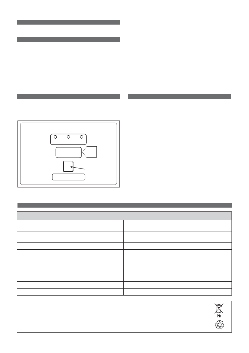
8. FRONT PANEL
CONTROL PANEL
Incorporates 5-digit display (1), selection button (2)
and 3 colors indicators
1. Five digit display to view
A
- charging current
U
- battery voltage
h
- charging time
C
- charging ampere-hours [Ah]
E
- energy consumption [KWh].
2. Selection button (S) for the display mode: A, U, h, C, E.
After about 10 seconds of each figure showed,
the display shows charging current.
3. Red control button, when it is on, the charging cycle has
started.
4. Yellow control button, when it is on, the final phase of
the charging cycle has started.
5. Green control indicator, when it is on, the charging
process has finished.
9. OPERATION
• Plug the charger into AC socket.
• Connect to the battery, check the polarity.
The front panel display will show following information:
• “Hawker” (recognizing the battery)
• Battery voltage
• Charging current
• Charging curve number
• Charging profile: “gel” or “acid”
Please make sure again that the charging profile matches
the battery type.
• After connection to the battery the “auto run” test is
initiated automatically.
The battery is ready for charging when the display shows
the battery voltage for approximately 5 seconds.
10. MESSAGES AND FAULT CODES
10.2012 - Subject to revisions without prior notice. E&OE
 Loading...