

Page 1
Installation, Operation
and Maintenance
Instructions
RESERVE
POWER
Page 2
2
www.enersys-emea.com
IMPORTANT
Please read this manual immediately on receipt of battery before
unpacking and installing. The installation and erection of batteries should
be undertaken by suitably qualified persons only. Failure to comply with
these instructions will render any warranties null and void.
CARE FOR YOUR SAFETY
Handling
DataSafe®MX batteries are supplied in a fully
charged state and must be unpacked carefully to
avoid very high short-circuit currents between
terminals of opposite polarity. Use care when
handling and moving batteries. Appropriate lifting
equipment must be used.
Keep flames away
In case of accidental overcharge, a flammable
gas can leak off the safety vent.
Discharge any possible static electricity from
clothes by touching an earth connected part.
Tools
Use tools with insulated handles.
Do not place or drop metal objects on the battery.
Remove rings, wristwatch and articles of clothing
with metal parts that may come into contact with
the battery terminals.
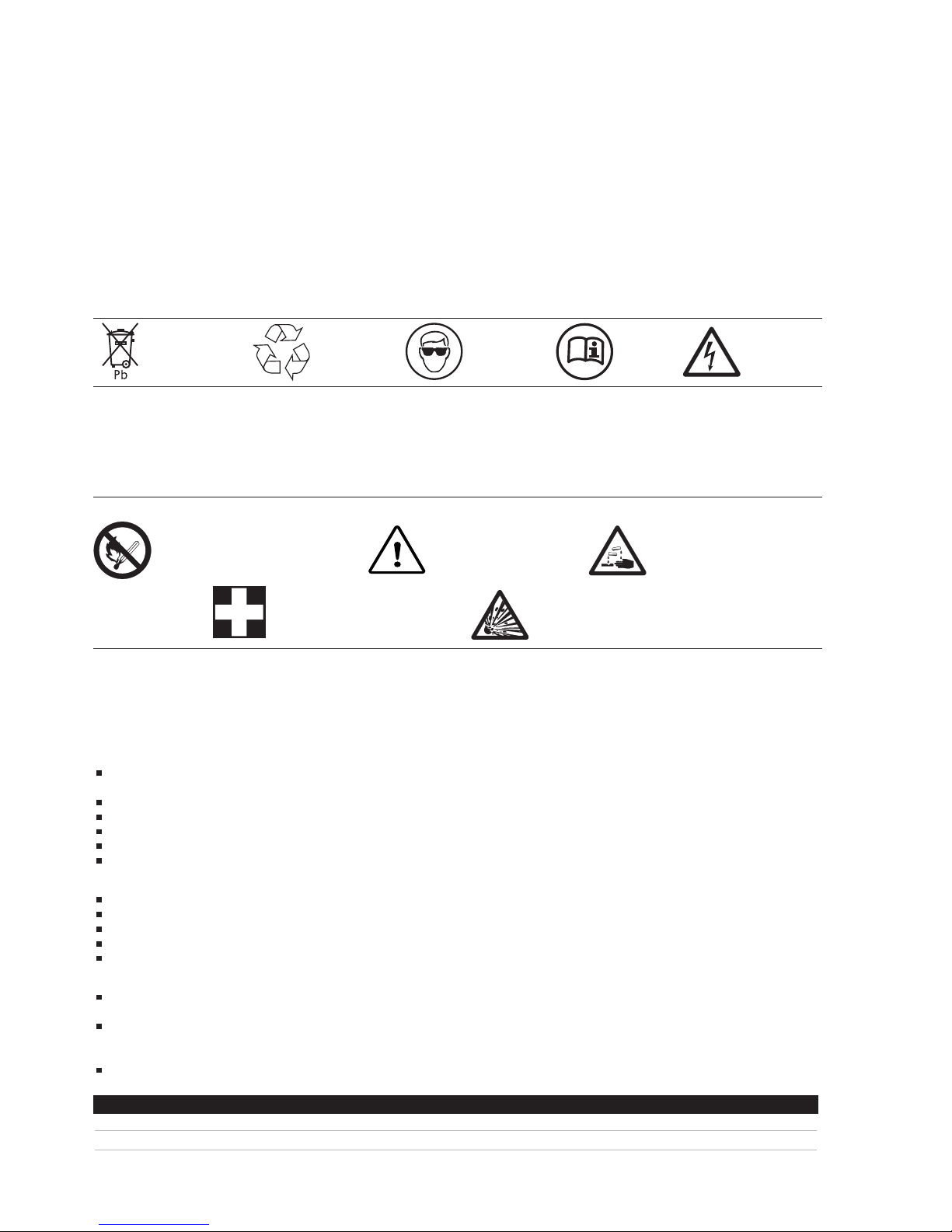
Dispose at registered
waste handling
facility
GENERAL GUIDELINES AND INFORMATION
HEALTH AND SAFETY
DataSafe MX batteries are electrically live at all times. Care must be taken
when handling the monoblocs, even when in a damaged or discharged
condition.
Always....
Remove all metal personal effects such as rings, metal watch bands,
belt buckles.
Switch off circuit before connecting or disconnecting battery.
Use insulated tools.
Keep sparks, flames and lighted cigarettes away from the battery.
Remember - batteries are heavy; use appropriate handling techniques.
Wear protective clothing, (eg., gloves, safety glasses, etc.)
Never....
Lift a battery by its terminals.
Charge in a sealed container.
Incinerate.
Short circuit.
Charge with a voltage greater than specified in this manual.
Storage
If the battery cannot be installed immediately, it should be stored in a
cool, clean and dry environment.
If the open circuit voltage drops to less than 2.09 Volts per cell, a
recharge will be necessary. The ambient temperature will affect the self
discharge and therefore the time between recharges.
Batteries should not be kept in a discharged condition.
TRANSPORTATION
DataSafe MX batteries are classed as ‘Non Hazardous’ for transportation by
air, sea or road. They may, therefore, be transported without restriction.
Notes- TREM Cards etc., provided the terminals are adequately protected
from short circuit. For air transportation ICAO (and IATA) special provision
A67 applies.
UNPACKING
On delivery, carefully examine the consignment for any obvious signs of
transit damage and then ensure that the goods are complete and agree
with the material list, advice note or invoice.
Monobloc terminal nuts and washers are normally packed in a sachet
inside the monobloc carton.
MONOBLOC CLEANLINESS
Please ensure that the monoblocs are clean at all times. Cleaning should be
carried out using a damp soft cloth.
Warning - Do NOT use any type of oil, solvent, detergent, petroleum-based
solvent or ammonia solution to clean the battery containers or lids. These
materials will cause permanent damage to the battery container and lid
and will invalidate the warranty.
No smoking, no naked flames,
no sparks
Electrolyte is corrosive
Clean all acid splash in eyes or on
skin with plenty of clean water.
Then seek medical help. Acid on
clothing is to be washed with water.
Danger
Warning: Risk of fire, explosion, or burns.
Do not disassemble, heat above 60ºC, or incinerate.
Avoid any short circuit. Metallic parts under voltage on the
battery, do not place tools or items on top of the battery
Other safety precautions that need to be taken
Battery must be
recycled
Protect eyes
from electrolyte
Read
instructions
Do not charge in
sealed container
Months on Shelf 0 1 2 3 4 5 6 7 8 9 10 11 12
State of charge (20°C) 100% 99% 97% 96% 95% 94% 93% 92% 91% 90% 90% 89% 88%
State of charge (30°C) 100% 97% 95% 93% 91% 90% 88% 86% 85% 84% 82% 81% 80%
Page 3
3
www.enersys-emea.com
CHARGING
FLOAT CHARGING (Preferred Method)
For maximum service life, DataSafe
®
MX batteries should be float charged
using a well regulated constant voltage.
CONSTANT VOLTAGE CHARGING (Recommended Charging Method)
Constant voltage charging is the most efficient and safest method of
charging a sealed lead acid cell. There are two methods of constant voltage
charging, float and fast.
1. FLOAT CHARGING
This type of charging is to be used in standby applications.
Note: For the battery to attain 100% capacity whilst being charged at
2.27 Vpc @ 20°C a minimum of 7 days recharge time is required.
Voltage Setting
When the DataSafe MX battery valve regulated cell is to be float charged in
a standby application, the constant voltage charger should be maintained at
2.27 Volts per cell whilst at an ambient temperature of 20°C for maximum
float life.
Temperature excursions away from this will cause a reduction in life for
high temperatures or a reduction in capacity due to undercharge at lower
temperatures. The general rule is that for every 10°C rise in temperature
there is a 50% reduction in the float life of the product.
Current Setting
There is no upper limit setting to the current requirements during constant
potential charging as the battery itself will regulate the current only
accepting as much as is required to reach its fully charged condition.
It should however be noted that the higher the charge current available
from the charging source, the quicker the battery will recharge.
In a fully charged float condition, at 20°C, DataSafe MX batteries will draw
between 5 and 50 milli-amps from the charger.
2. FAST CHARGING
2.1 CONSTANT VOLTAGE FAST CHARGING
In order to facilitate more rapid charging of the DataSafe MX battery, it is
possible to use the ‘fast’ charge technique, ideally suited to more cyclic
applications.
Voltage Setting
For applications requiring a faster recharge, a potential of 2.4 Volts per cell
at 20°C can be applied across the battery terminals. This will facilitate a
more rapid recharge although due to this higher potential it is
recommended that this level is maintained only until the current being
drawn by the battery has remained level for a period of 2 hours. Should this
recharge potential be applied for extended periods the battery might
become warm thus accelerating grid corrosion and reducing the service life
of the product.
Current Setting
As with float charging, the greater the current available from the charging
source the faster the recharge will be, with no limit being placed on that
charging current. However at these elevated voltages, the final stabilised
current being drawn from the charger as the battery reaches its full state of
charge will be higher than the values attained at 2.27 Volts per cell.
INSTALLATION
TOOLS AND MATERIALS REQUIRED
Insulated torque wrench.
See monobloc details in this section for the correct settings.
In adverse conditions, terminal grease, consisting of 20% lanolin in
petroleum jelly, can be used to protect the terminal against external
corrosive substances.
Whilst not harmful to the battery, silicone grease should not be used as this
can interfere with other electronic components.
MONOBLOC DETAILS
The following information is very important in optimising the operation of
the DataSafe MX battery:
To allow an even air flow around the monoblocs, and thereby improve the
dissipation of the small amount of generated heat, it is recommended, but
not essential, that an air gap of approximately 5mm is left between the
monoblocs.
Ensure that the correct torque setting of 3.9Nm or 2.9 lb ft is applied to the
terminal nuts.
Please Note: Over-tightening may result in damage to the
terminal.
When supplied with EnerSys®standard connectors, terminal shrouds are
already fitted. After the terminal nut is torqued down the shroud can be slid
over the terminal. The shroud is flexible, allowing a voltmeter probe tip to
be applied to the terminal.
It is good practice to assemble large batteries in sections, leaving out
connectors at, 48V intervals, so reducing the danger during the main part of
the installation. When the rest of the installation has been checked carefully,
the remaining connectors can be fitted.
Rack and cabinets should normally be filled starting from the bottom, thus
ensuring stability throughout the installation.
Where parallel strings of monoblocs are being used, strings should
normally be arranged on racks or cubicles so that there is thermal balance
within each string. In other words; three strings on a three row rack should
be arranged such that each string is spread across the three tiers.
Total lengths of cable/connector runs should be the same in each string
until the strings are combined at a transition box or circuit breaker.
Monobloc numbers, when provided, can be affixed to any part of the
monobloc plastic case EXCEPT over the vent disc(s) for future identification.
SITE ACCEPTANCE TESTS
OPERATION
A site acceptance test, consisting of a fully loaded discharge for the
required autonomy time, should be performed approximately 7 days after
installation and commissioning. EnerSys can give recommendations for
each application.
The following tables show the effect of battery temperature on the electrical
discharge performance at different discharge rates. Performance is given as
a percentage of the performance at 20°C.
TEMPERATURE
Rate 0°C 5°C 10°C 15°C 20°C 25°C 30°C 35°C 40°C
5m 67% 76% 85% 92% 100% 108% 116% 125% 133%
10m 73% 80% 86% 93% 100% 107% 113% 119% 125%
15m 74% 81% 87% 94% 100% 106% 111% 116% 121%
20m 76% 82% 88% 94% 100% 105% 110% 114% 118%
25m 77% 83% 89% 95% 100% 105% 109% 113% 117%
30m 78% 84% 90% 95% 100% 105% 109% 112% 116%
45m 80% 85% 91% 95% 100% 104% 107% 110% 113%
60m 81% 86% 91% 95% 100% 103% 107% 109% 111%
Figures apply to all DataSafe MX batteries.
The temperature expressed above relates to the monobloc, NOT ambient.
PUTTING INTO SERVICE
If the site acceptance test has been performed, the battery must then be
fully recharged.
LOW VOLTAGE DISCONNECTS
On-load battery voltage should not normally be allowed to fall below
1.7 Volts per cell for discharge times greater than 30 minutes. A low voltage
disconnect must always be used where possible to maintain the integrity of
the battery system. This should completely isolate the battery (including
removing any control circuit load) until power is fully restored to the
charging equipment.
Page 4

4
www.enersys-emea.com
MAINTENANCE AND INSPECTION
The optimum maintenance and inspection procedure will vary considerably
according to the application, number and critical nature of installations,
along with other commercial considerations.
It is advised that, in addition to the instructions detailed below, the Battery
Record Sheet as shown in Appendix B is utilised.
MONTHLY INSPECTION
SIX- MONTHLY INSPECTION
ANNUAL INSPECTION
As with monthly and six-month checks, the type of annual inspection is
based on the critical nature of installations, along with other commercial
considerations i.e. feasibility of reduced autonomy, manpower availability
etc. One method of checking the state of health of the battery is to perform
a partial discharge using the actual system as the load.
Example
For a system with a back-up autonomy time of 1 hours:
Switch off the main power supply and allow the battery to supply the
required back-up power to the load.
After approximately 15 minutes* measure and note the terminal voltage of
the individual monoblocs and the corresponding string from which the
measurement was taken. An example of a battery record sheet is shown in
Appendix B.
After all of the monoblocs have had their terminal voltages measured, the
main power should be returned to the system.
By reference to the noted values on the record sheet calculate the average
monobloc terminal voltage for each individual string.
From this value, calculate a voltage equating to 5% less than the average.
Monoblocs with a terminal voltage below the calculated value should be
considered for further monitoring or replacement to ensure maximum
system autonomy.
*The actual discharge duration is unimportant as the test is one of
comparison and does not have a specific pass/fail criteria. It should be
noted however that the longer the duration of the discharge is allowed to
continue before measurements are taken, the earlier it might be possible to
detect monoblocs prematurely failing.
It is only possible to check the actual capacity of the system battery by
performing a full discharge test on the battery to a known endpoint voltage.
Unfortunately, although this gives excellent battery maintenance cover,
it means that for a short period the battery will provide substantially
reduced autonomy. Hence this method should only be implemented during
times of complete system redundancy.
EnerSys
®
can design a tailor-made maintenance procedure when supplied
with the relevant information.
REJECT PROCEDURE AND DISPOSAL
REJECTION
Should a product, on receipt or otherwise, appear to be unserviceable
FIRST contact EnerSys detailing the circumstances.
Full details of date of shipment, commissioning records and all
maintenance records should be relayed.
DISPOSAL
All monoblocs for disposal should be shipped to a recognised scrap
recoverer, or regulated collection point.
EnerSys utilises a licensed reprocessor of lead and plastics. We will, at no
charge, dispose of batteries if they are delivered to our factory in Newport,
UK. Alternatively, please contact your local sales office who will be able to
assist with your disposal needs.
In the UK, this is a legal requirement and products should be disposed of in
accordance with the rules of the relevant Local Authority. The Local
Authority is required to maintain a list of their approved disposal and
recycling operators.
DO NOT INCINERATE END OF LIFE BATTERIES.
APPENDICIES
APPENDICIES
The following pages show the information listed below. If you have any
other requirements, please do not hesitate to contact our Sales Office or
your local agent.
APPENDIX A
THE DATASAFE
®
MX BATTERY RANGE - PRODUCT DETAILS
Notes- Weight is in Kg. A = Length; B = Width; C = Container; D = Height over terminals
Battery capacities increase with a higher temperature.
Unless otherwise stated all dimensions are in millimetres.
Battery Rating is measured in watts per cell at the 15 minute rate to
1.67 Volts per cell at 25°C.
For further information on any of our products, please contact our
Sales Office.
Measure total
battery voltage
1 Total battery
voltage on float
charge.
Adjust float
voltage as
specified in
Section 2
Recommended
float volts per cell
x number of cells
in series
Measure
individual
monobloc
voltages
2 Individual
monobloc
voltages on float
charge
Contact EnerSys
®
if non compliant
Within 5.0% of
the mean
Check for
damage or other
impairment
3 Appearance If a concern is
found check the
cause and replace
the monobloc as
necessary
Check for
contamination by
dust, etc.
4 Cleanliness If contaminated
ISOLATE
monobloc and
clean with a
damp soft cloth
Check for
corrosion of the
cubicle, battery
stand, connecting
cables and
terminals
5 General
condition
Perform cleaning,
corrosion
prevention
treatment,
painting, etc.
WHAT TO METHOD REQUIREMENT ACTION
INSPECT
Measure total
battery voltage
1 Total battery
voltage on float
charge.
Adjust float
voltage as
specified in
Section 2
Recommended
float volts per cell
x number of cells
in series
WHAT TO METHOD REQUIREMENT ACTION
INSPECT
12mx150 12 150 250 97 140 152 9.0 M6
12mx200 12 207 250 97 191 204 12.5 M6
12mx270 12 270 220 121 245 256 17.5 M6
Product Nominal Dimensions Typical Terminal
Type Voltage Rating A B C D Weight Thread
Page 5

5
www.enersys-emea.com
APPENDIX B
BATTERY RECORD SHEET
Site:
Monobloc type:
No series:
No parallel:
Battery Number:
Installation date:
Float Voltage:
Temperature:
Bank Number:
Inspection date:
1
2
3
4
5
6
7
8
9
10
11
12
13
14
15
16
17
18
19
20
21
22
23
24
25
26
27
28
29
30
31
32
33
34
35
36
37
38
39
40
41
42
43
44
45
46
47
48
49
50
51
52
53
54
55
56
57
58
59
60
61
62
63
64
65
66
67
68
69
70
71
72
73
74
75
76
77
78
79
80
81
82
83
84
85
86
87
88
89
90
91
92
93
94
95
96
97
98
99
100
101
102
103
104
105
106
107
108
109
110
111
112
113
114
115
116
117
118
119
120
121
122
123
124
125
126
127
128
129
130
131
132
133
134
135
136
137
138
139
140
141
142
143
144
145
146
147
148
149
150
151
152
153
154
155
156
157
158
159
160
161
162
163
164
165
166
167
168
169
170
171
172
173
174
175
176
177
178
179
180
181
182
183
184
185
186
187
188
189
190
191
192
193
194
195
196
197
198
199
200
201
202
203
204
205
206
207
208
209
210
211
212
213
214
215
216
217
218
219
220
221
222
223
224
Mb
No.
V/Mb
Mb
No.
V/Mb
Mb
No.
V/Mb
Mb
No.
V/Mb
Mb
No.
V/Mb
Mb
No.
V/Mb
Mb
No.
V/Mb
Mb
No.
V/Mb
Mechanical condition: Key:
Other observations: Mb = Monobloc
Signature: No. = Number
Organisation:
Page 6

6
www.enersys-emea.com
Notes:
Page 7

7
www.enersys-emea.com
Page 8

Contact:
© 2012 EnerSys. All rights reserved.
Trademarks and logos are the property of
EnerSys and its affiliates unless otherwise noted.
Publication No: EN-MX-IOM-002 - February 2012 - Subject to revisions without prior notice. E.&O.E.
www.enersys-emea.com
EnerSys
2366 Bernville Road
Reading, PA 19605
USA
Tel: +1-610-208-1991
+1-800-538-3627
Fax: +1-610-372-8613
EnerSys EMEA
EH Europe GmbH
Löwenstrasse 32
8001 Zurich, Switzerland
EnerSys Asia
152 Beach Road
Gateway East Building
Level 11
189721 Singapore
Tel: +65 6508 1780
EnerSys Ltd
Oak Court
Clifton Business Park
Wynne Avenue, Swinton
Manchester
M27 8FF, UK
Tel: +44 (0)161 794 4611
Fax: +44 (0)161 727 3809
 Loading...