

Page 1
APPLICATION MANUAL
1973 TO 2008
Publication No: EN-CYC-AM-007 - December 2008
Page 2

Wherever the world
needs stored energy,
EnerSys
Powered by more than 100 years
of expertise, EnerSys
world’s largest industrial battery
manufacturer, operating 21
facilities worldwide. Along with
manufacturing and distributing a
wide range of reserve power and
motive power batteries, chargers,
power equipment, and battery
accessories, EnerSys provides
unmatched aftermarket and
customer support to its customers
in over 100 countries worldwide.
®
is there.
®
is the
A rugged, reliable
alternative to
conventional lead
alloy batteries.
At first glance, a conventional lead battery may
seem like a better reserve-power deal than the
rechargeable, sealed-lead CYCLON
But a closer look reveals the real bottom line:
for long-term cost of ownership, there’s simply
no comparison. By housing a sealed, pure-lead,
thin-plate design within an extremely rugged steel
casing, CYCLON batteries outperform lead alloy
batteries in a number of ways:
• Per unit weight, CYCLON® batteries deliver
the greatest high-rate power density for
your energy dollar.
• CYCLON® batteries can be recharged to 95%
capacity in under an hour, and boast a design
life of ten years for single cell products and up
to eight years for monobloc products.
• CYCLON
in extreme applications and temperatures (up
to twice the capacity at -20°C) - and are safe
enough for installations in offices or hospitals.
®
batteries perform remarkably well
®
battery.
Add it all up and the real value of CYCLON batteries
becomes clear. Their power and extended service
life means more efficient operation with fewer
replacements, while their reliability means fewer
system failures. From general purpose to extremely
demanding applications CYCLON batteries simply
offer better performance and lower long-term cost
of ownership.
2
Page 3
Rugged construction and reliable performance
in extreme temperatures make Cyclon
®
batteries ideal for a range of applications:
• Telecommunications
• Defence installations
• Aerospace
• Global positioning
systems
• Uninterrupted
Power Supply (UPS)
Equipment
• Emergency lighting
• Medical equipment
• Computer back-up
• Electric vehicles
• Solar power
equipment
• General electronics
• Lawn and garden
equipment
8
3
Page 4

Powerful design:
A CYCLON® Single Cell
Resealable safety valve
A 50-PSI vent lets gases escape, then
automatically reseals, so there’s no risk
of excessive gas accumulation within the
battery, or “dry out” failure from repeated
recharges.
Pure lead plates
Made from 99.99% pure lead, CYCLON
battery plates are extremely thin, so they
offer more surface area than conventional
batteries - and far more power.
®
AGM plate separator
High-purity acid is absorbed right into
the Absorbed Glass Mat (AGM) plate
separators, so the CYCLON battery provides
leak-proof operation in any position.
Steel can enclosure
The CYCLON battery’s metal outer jacket
offers extreme shock, vibration, temperature,
and flammability protection.
www.enersys-emea.com
4
Publication No: EN-CYC-AM-007 - December 2008
Page 5

Table of Contents
Chapter 1: Introducing CYCLON® Batteries ..................................................................................................................... 6
1.1 Introduction ........................................................................................................................................................ 6
1.2 Sealed Design .................................................................................................................................................... 6
1.3 Low Temperature Performance ......................................................................................................................... 6
1.4 High Rate Charge & Discharge Capabilities ...................................................................................................... 6
1.5 Long Life in Float Applications .......................................................................................................................... 6
1.6 Structural Resistance ......................................................................................................................................... 6
1.7 Packing Flexibility .............................................................................................................................................. 6
1.8 High Power Density ........................................................................................................................................... 6
1.9 Transportation Classification ............................................................................................................................. 6
1.10 UL Component Recognition .............................................................................................................................. 7
Chapter 2: Physical Features ............................................................................................................................................. 7
2.1 Single Cell Construction .................................................................................................................................... 7
2.2 Monobloc Construction ..................................................................................................................................... 7
Chapter 3: CYCLON
3.1 Introduction ........................................................................................................................................................ 7
3.2 High Discharge Current ..................................................................................................................................... 7
3.3 Low Temperature Operation .............................................................................................................................. 8
3.4 Position Flexibility .............................................................................................................................................. 8
3.5 Recombinant VRLA Design ............................................................................................................................... 8
3.6 Shock & Vibration Characteristics ..................................................................................................................... 9
3.7 Float Life Characteristics ................................................................................................................................... 9
3.8 Cycle Life Characteristics .................................................................................................................................. 9
3.9 Fast Charging Characteristics ........................................................................................................................... 9
3.10 Storage Characteristics ..................................................................................................................................... 9
Chapter 4: Discharging CYCLON
4.1 Introduction ........................................................................................................................................................ 9
4.2 Discharge Voltage Profile ................................................................................................................................... 9
4.3 Discharge Level ............................................................................................................................................... 10
4.4 Overdischarge Recovery .................................................................................................................................. 10
Chapter 5: CYCLON
5.1 Introduction ...................................................................................................................................................... 11
5.2 State of Charge ................................................................................................................................................ 11
5.3 Storage ............................................................................................................................................................ 11
Chapter 6: Charging CYCLON
6.1 Introduction ...................................................................................................................................................... 11
6.2 General ............................................................................................................................................................. 11
6.3 Series-parallel CYCLON
6.4 Constant Voltage (CV) Charging ...................................................................................................................... 12
6.5 Fast Charging or Cyclic Charging .................................................................................................................... 12
6.6 Float Charging ................................................................................................................................................. 13
6.7 Temperature Compensation ............................................................................................................................ 13
6.8 Constant Current (CC) Charging ...................................................................................................................... 14
6.9 Taper Current Charging.................................................................................................................................... 15
Chapter 7: CYCLON
7.1 Introduction ...................................................................................................................................................... 15
7.2 Cycle Life ......................................................................................................................................................... 15
7.3 Float Life .......................................................................................................................................................... 16
®
Battery Benefits ............................................................................................................................. 7
®
Batteries .................................................................................................................... 9
®
Battery Storage ............................................................................................................................ 11
®
Batteries ....................................................................................................................... 11
®
Battery Systems ..................................................................................................... 12
®
Battery Service Life ..................................................................................................................... 15
Chapter 8: Safety Issues .................................................................................................................................................. 16
8.1 Introduction ...................................................................................................................................................... 16
8.2 Gassing ............................................................................................................................................................ 16
8.3 Shorting............................................................................................................................................................ 17
Appendix A ............................................................................................................................................................................ 17
Appendix B .............................................................................................................................................................. Back Cover
www.enersys-emea.com
Publication No: EN-CYC-AM-007 - December 2008
5
Page 6

Chapter 1:
Chapter 1:
Introducing the Genesis Battery
Introducing CYCLON® Batteries
1.1 Introduction
The purpose of this guide is to describe the characteristics
of the sealed-lead family of rechargeable CYCLON
batteries from EnerSys
®
in its many different applications.
®
cells and
The unique cylindrical design overcomes many limitations
of competitive lead-acid systems without sacrificing cost
effectiveness, reliability, ruggedness and long life which have
always been assets of the lead-acid battery. Some of the
features are described below.
1.2 Sealed Design
Individual cells and monobloc batteries are sealed to prevent
electrolyte leakage. Since the cell operates during its normal
life without loss of water, even during continuous overcharge,
no water or electrolyte checks are required. Because of the
sealed design, the cell, monobloc or battery assembly can be
oriented in any position for ease of installation. In addition, the
combination of a sealed design and a mechanically operated
resealable Bunsen valve allows the cell to be operated even in
a vacuum.
1.6 Structural Resistance
The rugged outer metal case of the single cell design
increases its resistance to shock, crushing or damage due
to dropping, while allowing a very high vent pressure of 50
pounds per square inch (psi) or about 3.4 atmospheres (atm).
The cylindrical shape of the monobloc case also allows the
highest plastic case vent pressure of 8 psi (0.54 atm), as well
as providing resistance to case distortion due to heat.
1.7 Packing Flexibility
All CYCLON battery single cells can be used in parallel for
additional capacity. The individual cell construction allows
the battery to be laid out inside a battery cavity in an almost
infinite variety of patterns, maximising space utilisation. Heat
sealed combinations of the monoblocs add to the flexibility of
mounting configurations as well as contributing to savings in
space requirements.
1.8 High Power Density
CYCLON batteries have very high power density, particularly
at high rates of discharge. Please refer to Appendix A for
several graphs and charts that detail these capabilities.
1.3 Low Temperature Performance
The exceptional low temperature performance of CYCLON
batteries have been made possible by the use of plates that
provide a high surface area, coupled with a separator system
that minimises diffusion and resistance effects. This results
in good utilisation of active material and excellent voltage
regulation over a wide temperature range.
1.4 High Rate Charge & Discharge Capabilities
The thin plate construction of CYCLON batteries contribute
to high utilisation of the active plate materials and very
low internal impedance. This means that the cells can be
discharged at high rates, allowing the use of smaller batteries
for short duration, high rate discharges. Another advantage of
the very low internal resistance is the fast recharge capability.
Depending on the depth of discharge and charge current
available, the CYCLON battery cell can be fully charged in a
few hours.
1.5 Long Life in Float Applications
The high purity of the lead-tin grid (the purity of the lead
is in excess of 99.99%) used in CYCLON battery cells
results in long life on float charge. Depending on the ambient
temperature and the specific product (single cell
or monobloc) selected, one can get up to ten (10) years
float life at 25°C and 15 years float life at 20°C.
1.9 Transportation Classification
The Department of Transportation (DOT) has classified all
CYCLON batteries as “nonspillable wet electric storage
batteries.” Having been tested and found in compliance
with section 173.159 (d) of the 49 CFR, subchapter 173.159,
CYCLON batteries are exempt and unregulated regarding
shipping requirements of DOT 173.159. As a result, CYCLON
batteries do not have an assigned UN number, nor do they
require additional DOT hazard-communication labeling or
placarding. CYCLON
®
batteries may be shipped by air or
ground transportation without restriction.
CYCLON batteries and their outside shipping container
must be labeled “nonspillable” or “nonspillable battery.”
This labeling requirement is to clarify and distinguish to
shippers and transporters that all batteries have been tested
and determined to be in compliance with DOT HMR 49 NonHazardous Materials, and International Civil Aeronautics
Organisation (ICAO) and International Air Transport (IATA)
Packaging Instruction 806 and Special Provision A67 Vibration
and Pressure Differential Tests, and are therefore unregulated
and classified as “nonspillable wet electric storage
battery.”
®
www.enersys-emea.com
6
Publication No: EN-CYC-AM-007 - December 2008
Page 7
All CYCLON® cells and batteries are packaged, marked,
labeled, and documented according to the appropriate
transportation regulations when shipped from an EnerSys
facility. A shipper that fails to follow these same requirements
may be subject to substantial civil and/or criminal penalties
and may cause a safety hazard.
All CYCLON battery packages must be capable of
passing International Safe Transit Association (ISTA)
Procedure 1A testing.
Packages weighing no more than 20 lbs. must be
packaged in a minimum 200 lb. burst strength or 32
ECT certified carton.
Packages weighing over than 20 lbs. must be packaged in
a minimum 275 lb. burst strength or 44 ECT certified carton.
No individual package can exceed a total gross weight
of 70 lbs.
It is the responsibility of the shipper to ensure each employee
who directly affects hazardous material/dangerous goods
transportation safety is appropriately trained in accordance
with the selected mode of transportation.
The terminals of CYCLON battery cells can cause shorts
if they are not insulated during shipping. Protective caps
or other durable inert material must be used to insulate
each terminal of each cell unless cells are shipping in the
original packaging from EnerSys in full box quantities.
Protective caps are available for all cell sizes by
contacting EnerSys Customer Service at 1-800-964-2837.
International customers should call 1-660-429-6437.
Assembled batteries must have short circuit protection during
shipping. Exposed terminals, connectors, or lead wires must
be insulated with a durable inert material to prevent exposure
during shipping.
FAILURE TO COMPLY WITH THESE REQUIREMENTS CAN
CAUSE A FIRE DURING SHIPPING AND HANDLING!
®
The external spade terminals on CYCLON battery
single cells are inserted through the polypropylene inner top
and are effectively sealed by expansion into the lead busbars.
The element is then stuffed into the jar liner and the inner top
and liner are bonded together. At this state of construction,
the cell is sealed except for the open vent hole.
A unique vacuum fill process then adds sulphuric acid and
the Bunsen relief valve is placed over the vent hole. In the
manufacture of a single cell, the sealed element is then
inserted into the metal can, an outer plastic top added and
crimping completes the assembly. The metal case is for
mechanical strength and is the principal factor contributing to
the high pressure rating of the resealable vent. The cell is now
charged for the first time (electrochemically formed).
2.2 Monobloc Construction
The monobloc construction differs from single cell
construction as it is essentially a battery consisting of multiple
cells, each cell element inserted in a single plastic container.
Spade terminals are inserted into the molded openings
connecting internally to the plate tab lead busbars. Intercell
plate tabs are connected by through-the-wall welds. Acid is
added using the vacuum fill process, the cover is heat sealed
in place and a Bunsen relief valve installed.
The battery is now formation charged.
Chapter 3:
CYCLON® Battery Benefits
3.1 Introduction
This chapter is devoted to describing specific performance
characteristics of CYCLON batteries that make them
a superior battery choice, particularly for demanding
applications such as temperature extremes typically
encountered in outdoor environments.
1.10 UL Component Recognition
All CYCLON batteries are recognised as UL components.
Chapter 2:
Physical Features
2.1 Single Cell Construction
Both the positive and negative plates are made of pure leadtin and are extremely thin. The plates are pasted with lead
oxides, separated by an absorbing glass mat separator and
spirally wound to form the basic element. Lead busbars are
then welded to the exposed positive and negative plate tabs.
www.enersys-emea.com
3.2 High Discharge Current
CYCLON battery cells can be discharged at very high
currents while maintaining a reasonably flat voltage profile.
This characteristic is achieved because of the high plate
surface area and closeness of the plates to each other due to
the use of thin plates in a spirally wound construction.
Typical maximum current capabilities of single cells and
monoblocs are shown in Table 3-1 below. In all cases, the
duration of discharge is one (1) minute to 1.50 volts per cell at
an ambient temperature of 25°C (77°F).
Publication No: EN-CYC-AM-007 - December 2008
7
Page 8
Higher currents than those shown in the table may be
maintained for durations shorter than one minute. The
ability of the cell or monobloc to maintain higher currents
is dependent on the magnitude of the current, its duration,
the frequency of its application and, most importantly, on
the ability of the terminal connection to act as a heat sink
and dissipate the heat generated. For high rate applications
we strongly recommend testing under actual or simulated
application conditions.
Table 3-1
CYCLON
®
Battery Type Max. amps to 1.50 VPC
D single cell (2.5Ah) 65
Tall D single cell (4.5Ah) 65
D monobloc (2.5Ah) 50
X single cell (5.0Ah) 65
E single cell (8.0Ah) 65
X monobloc (5.0Ah) 50
E monobloc (8.0Ah) 50
J single cell (12.0Ah) 100
BC single cell (25.0Ah) 250
3.3 Low Temperature Operation
Exceptional low temperature characteristics are maintained
through the use of a separator system that minimises
resistance and diffusion effects. This feature, combined with a
large plate surface area, results in efficient utilisation of active
materials and excellent voltage regulation.
Because the cell operates as a "starved" electrolyte system,
there is only enough electrolyte to maintain the rated capacity
of the cell. The capacity available at low temperatures is a
function of both temperature and discharge current.
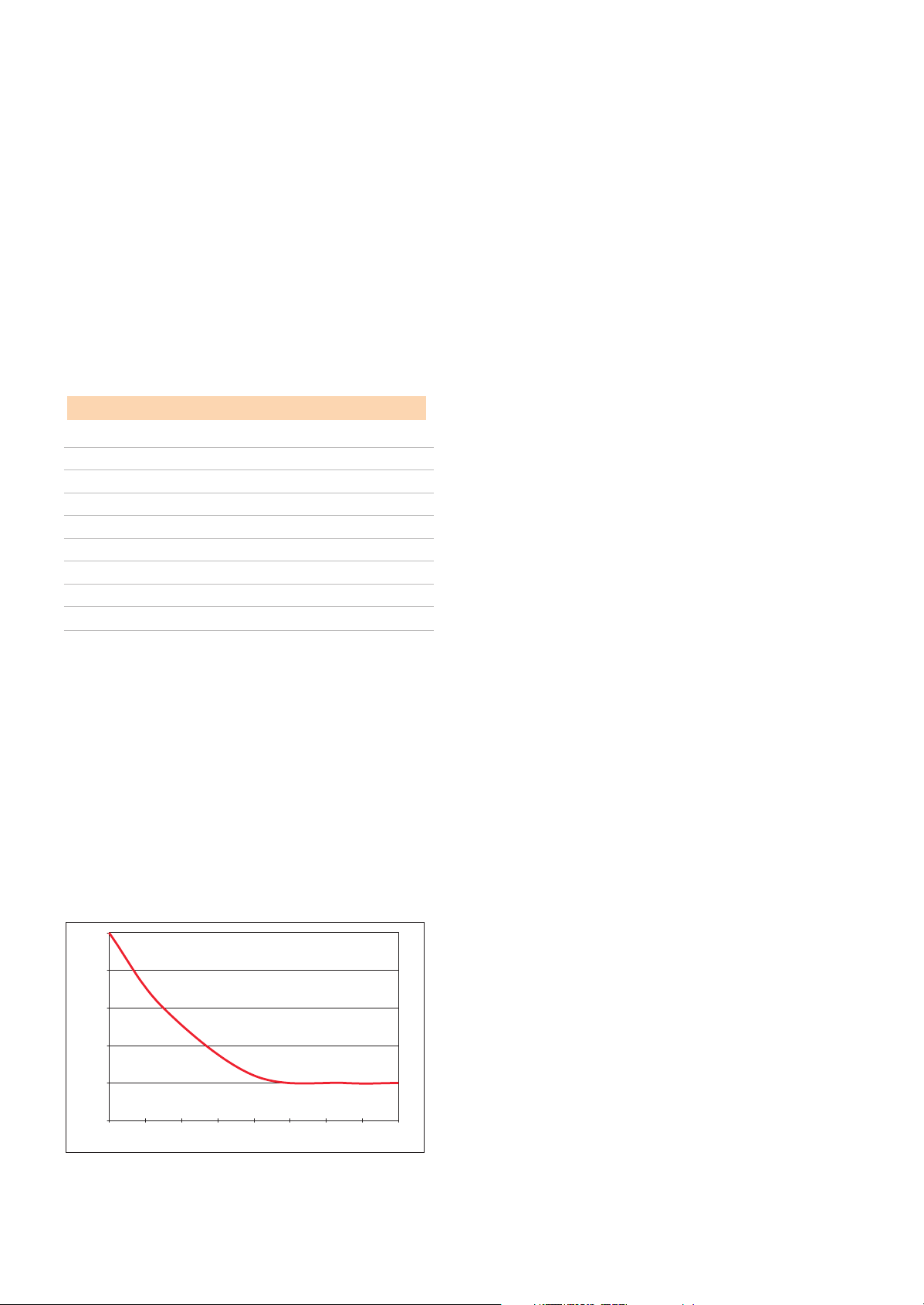
Figure 3-1 shows another reason why CYCLON
®
battery cells
have good discharge performance at low temperatures.
Figure 3-1: Internal Resistance Vs. Temperature
500
400
lanimon % ,ecnatsiser .tnI
300
200
As the temperature drops, the increase in internal resistance
is relatively gradual down to a little under 0°C (32°F). This
also explains why CYCLON battery cells have excellent low
temperature performance.
3.4 Position Flexibility
With the starved electrolyte system, the sulphuric acid
is absorbed within the cell plates and the glass mat separator.
The cell is virtually dry with no free electrolyte, allowing it
to be charged, discharged or stored in any position without
electrolyte leakage.
3.5 Recombinant VRLA Design
One of the most important features of the CYCLON battery
design is its recombinant valve regulated lead-acid (VRLA)
design. This mode of operation is possible because the cell is
able to use the oxygen cycle during overcharge. The oxygen,
evolved at the positive electrode when the cell is overcharged,
is recombined at the negative electrode. A self-resealing valve
is provided as a safety vent in case of misapplication or other
abuse of the cell that would cause the internal cell pressure to
increase.
In CYCLON batteries, water loss is greatly reduced due to two
design features. First, because water tends to decompose
around impurities in the lead, the rate of such decomposition
is reduced due to the high purity of the lead used in CYCLON
batteries. Second, the use of high pressure seals contains the
gases within the cell, promoting more efficient recombination.
In a conventional lead-acid cell, the charge current
electrolyses the water to produce hydrogen from the negative
electrode and oxygen from the positive electrode. Thus water
is lost from the cell, and it must be replenished by means of
frequent topping up with water.
The evolution of the two gases does not occur at the same
time due to the fact that the recharge efficiency of the positive
electrode is less than that of the negative electrode. This
means that oxygen is evolved from the positive plate before
the negative plate can generate hydrogen.
As oxygen is evolved from the positive plate, a significant
quantity of highly active spongy lead exists on the negative
electrode before the negative plate can generate hydrogen.
If the oxygen that is generated by the positive plate can be
transported to the negative plate, the spongy lead will react
rapidly with the oxygen to form lead oxide as shown by the
following reaction:
2Pb + O
2 ➔ 2PbO (Eqn. 1)
100
0
-4 -30 -20 -10 0 10 20 30 40
www.enersys-emea.com
8
Temperature, ºC
Publication No: EN-CYC-AM-007 - December 2008
Page 9

The movement of oxygen from the positive electrode to the
negative electrode is facilitated by the use of highly porous
separators that allow the oxygen to diffuse within the cell
and cause the reaction defined by Equation 1. The acidic
conditions prevailing inside the cell is very conducive to the
reaction between lead oxide and the sulphuric acid to form
lead sulphate in accordance with Equation 2 below:
2PbO + 2H
2SO4 ➔ 2PbSO4 + 2H2O (Eqn. 2)
As the lead sulphate is deposited on a surface that generates
hydrogen, it (lead sulphate) is reduced to lead and sulphuric
acid as indicated by Equation 3:
2PbSO
4 + 2H2 ➔ 2Pb + 2H2SO4 (Eqn. 3)
Adding the three equations and cancelling out like terms on
either side of the equations, we obtain Equation 4:
2H
2 + O2 ➔ 2H2O (Eqn. 4)
These four equations show the reactions that form the
principle of recombination that is employed by the CYCLON
battery product line. By properly designing the cell,
recombination efficiencies in excess of 99% are achieved in
the CYCLON batteries.
3.9 Fast Charging Characteristics
Efficient fast charging can be accomplished using a constant
voltage charger. With an initial charge current capability in
the 2C
1
10
range the cell can be recharged to better than 95%
state of charge in less than one hour. Applications using
fast charging must allow for periodic extended charging to
maximise life.
3.10 Storage Characteristics
The CYCLON battery cell and monobloc may be stored
for up to two years at room temperature (25°C or 77°F)
and recharged with no loss in cell reliability or performance
capabilities. The recharge may be accomplished without
resorting to special charging techniques.
When batteries are stored at or near 25°C (77°F) we
recommend conducting an OCV audit every 12 months and
recharging when OCV readings approach 2.00 volts
per cell (VPC). If storage temperatures are significantly higher
than 25°C (77°F), even for short durations, the frequency of
®
OCV audits must be increased.
Chapter 4:
Discharging CYCLON
®
Batteries
3.6 Shock & Vibration Characteristics
The spirally wound plate element is compressed within a
polypropylene liner or case, minimising plate movement
in high shock or vibration applications. Movement in a
vertical direction is also limited by the polypropylene lid
design. Overall, the cell has excellent shock and vibration
characteristics.
3.7 Float Life Characteristics
As noted previously, life expectancy of CYCLON batteries is
not limited by loss of electrolyte due to the sealed design.
Instead, life expectancy is determined by long-term corrosion
of the positive current collecting grid. The corrosion effect on
cell capacity is minimal until the cell approaches end-of-life,
which is defined as the inability of the cell to provide at least
80% of its rated capacity compared to that of 50% from a
standard AGM.
3.8 Cycle Life Characteristics
The cycle life of the cell in an application will be a function
of the depth of discharge (DOD), temperature and charging
rate. Depending on the DOD, the cycle life available can vary
from 300 to more than 20,000. However, to get these cycle
numbers, the battery must be recharged effectively.
4.1 Introduction
Discharge tables and curves for CYCLON batteries are
shown in Appendix A. The capacity available from a cell is a
complex function of the state of charge, temperature, the rate
of discharge and the end of discharge voltage (EODV). The
tables provide the discharge performance of these cells to
various EODVs. The graphs provide the same information but
only to three EODVs.
4.2 Discharge Voltage Profile
Figures 4-1 and 4-2 show the room temperature (25°C/77°F)
voltage profile of CYCLON battery cells when subjected to
four loads - C
10/10, C10/5, 1C10 and 2.2C10.
In all cases, the low internal resistance of the cells allows very
stable voltage profiles, regardless of whether the discharge is
moderate (C
10/5 to C10/10) or at a high rate (1C10 to 2.2C10).
1
The C10 rate of a battery is defined as the charge or discharge current in amperes that is numerically equal to the rated capacity of a cell in ampere-
hours at the 10 hr rate of discharge. Thus the 2C
www.enersys-emea.com
10 rate for a 5Ah cell would be 10 amps.
Publication No: EN-CYC-AM-007 - December 2008
9
Page 10

Figure 4-1: CYCLON
®
Battery Medium Rate Discharge
Voltage Profile
2.3
2.2
2.1
2
1.9
1.8
1.7
Cell Voltage (V)
1.6
01
2 3 4 5 6 7 8 9 10 11 12
Time in hours at 25°C (77°F)
C/5 C/10
Figure 4-2: CYCLON
2.3
2.2
2.1
2
1.9
1.8
1.7
1.6
1.5
Cell Voltage (V)
1.4
0 5 10 15 20 25 30 35 40 45 50 55
®
Battery High Rate Voltage Profile
1C 2.2C
Time in minutes at 25°C (77°F)
4.3 Discharge Level
The voltage point at which 100% of the usable capacity
has been depleted is a function of the discharge rate. For
optimum cell life, it is recommended that the battery be
disconnected from the load at this end voltage point. The
recommended end of discharge voltage (EODV) is a function
of the rate of discharge, and these numbers are given in Table
4-1 below:
Table 4-1
Discharge rate in amps Suggested minimum
EODV per cell
0.05C
0.10C
0.20C
0.40C
1.00C
2.00C
>5.00C
NOTE: Discharging a CYCLON® battery cell below these voltage levels
10 (C10/20) 1.75V
10 (C10/10) 1.70V
10 (C10/5) 1.67V
10 (C10/2.5) 1.65V
10 1.60V
10 1.55V
10 1.50V
or leaving the cell connected to a load in a discharged state
may impair the ability of the cell to accept a charge.
In "overdischarge" conditions, the sulphuric acid electrolyte
can be depleted of the sulphate ion and essentially become
water, which can create several problems. A lack of sulphate
ions as charge conductors will cause the cell impedance to
appear high and little charge current to flow. Longer charge
time or alteration of charge voltage may be required before
normal charging can resume.
Disconnecting the battery from the load will totally eliminate
the possibility of an overdischarge, provided that it is put
back on recharge immediately after the discharge. Doing so
will allow each cell to provide its full cycle life and charge
capabilities.
It is important to note that when the load is removed
from the battery, its terminal voltage will increase - up to
approximately 2 volts per cell. Because of this phenomenon,
some hysteresis must be designed into the battery disconnect
circuit so that the load is not continuously reapplied to the
battery as the battery voltage recovers.
4.4 Overdischarge Recovery
Although overdischarging the battery is not recommended,
CYCLON
®
batteries have an excellent tolerance for this type
of abuse. The following protocol may be used to recover cells
that have been overdischarged. This procedure should not be
attempted if the OCV of the battery pack is 1.0 volt per cell
(VPC) or less.
1. Bring the battery to room temperature (77ºF or 25ºC).
2. Measure the OCV. Continue to step 3 if it is at least 1.00
VPC; otherwise terminate the procedure and reject the
battery.
3. Charge the battery using a 0.05C constant current
for 24 hours. The charger should be able to provide a
driving voltage as high as 3.0 VPC. Monitor the battery
temperature; discontinue charging if the battery
temperature rises by more than 20ºC.
4. Allow the charged battery to stand on open circuit
for 18 hours.
5. Perform a capacity test on the battery and record the amp-
hours delivered. The longer the discharge the more reliable
the result. This is Cycle 1.
6. Repeat steps (3) to (5). The capacity returned in step 5 is
now Cycle 2. If Cycle 2 capacity is greater than Cycle 1
capacity proceed to step 7; otherwise reject the battery.
7. Repeat steps (3) to (5) to get Cycle 3 capacity. Proceed to
step 8 if Cycle 3 capacity is equal to or more than Cycle 2
capacity. Reject the battery if Cycle 3 capacity
is less than Cycle 2 capacity.
8. If Cycle 3 capacity equals or exceeds Cycle 2 capacity
recharge the battery and put it back in service.
www.enersys-emea.com
10
Publication No: EN-CYC-AM-007 - December 2008
Page 11

Chapter 5:
CYCLON® Battery Storage
Figure 5-2: CYCLON
Temperature
®
Battery Storage Time Vs.
5.1 Introduction
Another area where the CYCLON
®
battery product has a
significant advantage over conventional sealed-lead batteries
is storage. This chapter devotes itself to offering the reader
useful information on properly exploiting the long storage
(shelf) life of CYCLON battery cells and monoblocs.
5.2 State of Charge
The state of charge (SOC) of the CYCLON battery cell can
be approximated by using the curve given in Figure 5-1. This
curve is accurate to within 20% of the true SOC of the cell
under consideration, if it has not been charged or discharged
within the past 24 hours. The curve is accurate to within 5% if
the cell has not seen any activity, charge or discharge, for the
past 5 days.
Figure 5-1: CYCLON
®
Battery Open Circuit Voltage
Vs. State of Charge
2.17
2.14
2.11
2.08
2.05
2.02
OCV, V
1.99
1.96
1.93
1.9
10 20 30 40 50 60 70 80 90 100
State of Charge, %
5.3 Storage
Most batteries lose their stored energy when allowed to stand
on open circuit due to the fact that the active materials are in
a thermodynamically unstable state. The rate of self-discharge
is dependent both on the chemistry of the system as well as
on the temperature at which the battery is stored.
All CYCLON batteries are capable of long storage without
damage. Figure 5-2 is a plot of maximum storage time as
a function of storage temperature. This curve shows the
maximum number of days at any given temperature, from
10°C (50°F) to 65°C (149°F), for the cell to discharge from
a fully charged state (about 2.14 volts per cell) down to zero
state of charge (1.93 volts per cell). The cell should not be
allowed to discharge below 1.93 volts because of the danger
of damaging the performance characteristics of the cell
permanently.
3000
1000
100
Storage time, days
10
10 20 30 40 50 60 70
Storage temperature, °C
It is important to recognise that the self-discharge rate
of CYCLON batteries is non-linear. Thus, the rate of selfdischarge changes as the SOC of the cell changes. In other
words, the time taken for a cell to discharge from a 100%
SOC to 90% SOC is very different from the time it takes to
self-discharge from a 20% SOC to a 10% SOC.
Chapter 6:
Charging CYCLON® Batteries
6.1 Introduction
The superior charging characteristics of CYCLON batteries
makes them the power source of choice in demanding
applications that require rapid charging. Conventional
sealed-lead batteries are not suited for this type of charging
where charge currents can be of the order of 2C
6.2 General
Charging CYCLON sealed-lead acid products, like charging
other rechargeable batteries, is a matter of replacing the
energy depleted during the discharge. Because this process is
not 100% efficient, it is necessary to return more than 100%
of the energy removed during the discharge.
The CYCLON battery cell uses the gas recombination
principle that allows up to 100% of the oxygen generated at
up to the C
10/3 overcharge rate to be recombined to form
water at the negative plate, eliminating oxygen outgassing.
Hydrogen gas generation has been substantially reduced
by the use of pure lead-tin grid material, which has high
hydrogen overvoltage. The corrosion of the positive current
collecting grid has been reduced by the use of pure lead-tin.
The amount of energy necessary for a complete recharge
depends upon how deeply the cell has been discharged, the
method of recharge, the recharge time and the temperature.
Typically, between 105% and 110% of the discharged
ampere-hours must be returned for a full recharge. Thus, for
every ampere-hour discharged, one must put back between
1.05 and 1.10 ampere-hours to ensure a full recharge.
10 or higher.
www.enersys-emea.com
Publication No: EN-CYC-AM-007 - December 2008
11
Page 12

If watt-hours rather than ampere-hours are measured, the
required overcharge factor will be higher. It is important to
note that although the battery can deliver at or near its full
capacity prior to receiving the required overcharge, in order to
obtain long cycle life, the battery must periodically receive the
required overcharge.
Charging can be accomplished by various methods. The
objective is to drive current through the cell in the direction
opposite that of discharge. Constant voltage (CV) charging
is the conventional method for charging lead-acid cells, and
is acceptable for CYCLON
®
battery cells. However, constant
current (CC), taper current and variations thereof can also be
used.
rate at which the charger is limited. In other words, if the
charger is limited to the C
10/10 rate, then 10 hours should be
added, giving a total charge time of 26 hours. Using the same
rule, if the charger is limited to the C
10/5 rate, then 5 hours
should be added and recharge would require about 21 hours
instead of 16 hours.
Note that there are no practical limitations on the maximum
current imposed by the charging characteristics of the
CYCLON battery cell under constant voltage charge.
NOTE: It is important to keep in mind that for cyclic applications the
charge voltage must be in the 2.45 to 2.50 volts per cell (VPC)
range. Lowering the voltage to under 2.45 VPC in such an
application will lead to a rapid loss in capacity, regardless of the
magnitude of the inrush current.
6.3 Series-parallel CYCLON
®
Battery Systems
While there are no theoretical limits on the number of parallel
strings in a CYCLON battery pack, in practical situations that
limitation is imposed by (a) whether the application is floating
or cyclic in nature and (b) the charger design.
To avoid charge imbalance in a cyclic application, there
should be no more than five (5) parallel strings. Further, the
minimum inrush current that the charger should be able to
provide, assuming single step constant voltage charger is
5C for a five-string system. If a more sophisticated charge
algorithm such as the adaptive IUI charge profile is used,
the minimum inrush can be reduced to 2C for the five-string
battery pack, allowing 0.4C charge current per string.
These minimum current values are critical in a cyclic
environment as the battery is on charge for only limited
periods of time, creating a potential for significant
undercharge. Undercharging batteries in cyclic applications
leads to premature capacity loss and early end of life.
Batteries in a float application spend most of their time on
float charge. This allows all strings in a series-parallel system
to be charged adequately, eliminating the need to restrict the
number of parallel strings. However, it is still good practice
to have no more than five parallel strings, regardless of the
nature of the application.
6.4 Constant Voltage (CV) Charging
Constant voltage (CV) charging is the most efficient method of
charging CYCLON battery sealed-lead products.
Tables 6-1 and 6-2 in the next section on fast charging show
the recharge times as a function of charge voltage and inrush
current at 25°C (77°F). The minimum inrush current for single
voltage level charging is of the order of 0.4C
10 (C10/2.5), and
one must allow about sixteen (16) hours for a full charge
under repetitive cycling conditions. If the CV charger that is
used has an inrush current less than C
10/2.5, then either the
charge time allowed must be increased or special charge
algorithms must be evaluated.
Generally speaking, when the initial current is less than
C
10/2.5, the charge times must be lengthened by the hourly
6.5 Fast Charging or Cyclic Charging
A fast charge is broadly defined as a method of charge that
will return the full capacity of a cell in less than four hours.
However, many applications require a return to a high state
of charge in one hour or less. Prior to the development of
CYCLON batteries, commercially available lead-acid batteries
required charging times of greater than four hours to be
brought up to a high state of charge.
Unlike conventional parallel flat plate lead-acid cells, the
CYCLON battery cell uses a starved electrolyte system where
the majority of the electrolyte is contained within a highly
retentive fibrous glass mat separator, creating the starved
environment necessary for homogeneous gas phase transfer.
The gassing problem inherent in flooded electrolyte sealedlead batteries that utilised alloyed lead is not evident with
the CYCLON battery system, as the extremely high purity
of lead minimises the oxygen and hydrogen gas generation
during overcharge and any oxygen gas generated is able to
recombine within the sealed cell. The high plate surface area
of the thin plates used in CYCLON battery cells reduces the
current density to a level far lower than normally seen in fast
charge of conventional lead-acid cells, thereby enhancing the
fast charge capabilities.
Tables 6-1 and 6-2 display the relationships between charge
rate and percent of previous discharge capacity returned to
the cell vs. time at 2.45 volts per cell CV charge. Prior to the
recharges, the CYCLON battery cell were discharged to 100%
DOD.
www.enersys-emea.com
12
Publication No: EN-CYC-AM-007 - December 2008
Page 13

Table 6-1 (1.5C10 inrush)
Charge time at 2.45VPC Capacity Returned
17 min. 50%
27 min. 80%
31 min. 90%
60 min. 100%
Table 6-2 (2.5C
10 inrush)
Charge time at 2.45VPC Capacity Returned
12 min. 50%
19 min. 80%
24 min. 90%
40 min. 100%
These tables demonstrate the superior fast charge capabilities
of the CYCLON
Table 6-1 were generated using an initial current in the 1.5C
®
line of sealed-lead batteries. The numbers in
10
range while those in Table 6-2 were generated using a current
limit in the 2.5C
10 range.
Increasing the magnitude of the inrush current has a dramatic
impact on the total time to recharge the cells -only 40 minutes
to return 100% of previously discharged capacity at 2.5C
compared with 60 minutes at 1.5C
10 to reach the same mark.
10
This is a useful result to keep in mind when designing battery
systems for applications that require rapid opportunistic
charging.
Although CYCLON battery cells do not require a current limit
(initial current inrush) when being charged by a CV source,
most practical applications have chargers that have limited
power handling capabilities, thereby also restricting the
current limit.
Cyclic charging tests were conducted using a CV charger
that had only a 1A (C
10/2.5 on a 2.5Ah cell) current limit and
the charge times shown in Table 6-3. The charge voltage,
however, was set at 2.45 VPC. The last column shows the
number of cycles one may expect for specific DOD numbers.
Table 6-3
Depth of Charge
discharge, %
2
3
time, hr. Number of cycles
Up to 30 5 2500
31 to 50 8 1700
51 to 100 16 300
6.6 Float Charging
When CYCLON battery products are in a purely float
application at an ambient temperature of 25°C (77°F), the
recommended charge voltage setting is 2.25 to 2.30 volts per
cell (VPC). We also recommend that this charge voltage be
temperature compensated, as outlined in the next section.
6.7 Temperature Compensation
High temperatures accelerate the rate of the reactions that
reduce the life of a cell. At increased temperatures, the
voltage necessary for returning full capacity to a cell in a
given time is reduced because of the increased reaction rates
within the battery.
To maximise life, a negative charging temperature coefficient
of approximately ±3mV per cell per °C variation from 25°C
(77°F) is used at temperatures significantly different from
25°C (77°F). This coefficient is negative - as the ambient
temperature increases the charge voltage must be reduced,
and vice versa. Figure 6-1 shows the variation of float voltage
with temperature.
It is important to note that even if the charge voltage is
perfectly compensated for high ambient temperature, the
float life expectancy of the cell would still be reduced.
This is due to the fact that while the charge currents are
lowered because of lower charge voltages, the high ambient
temperature continues to have a negative influence on the life
of the battery. Thus, temperature compensation of the charge
voltage only partially offsets the impact of high ambient
temperature on the float life of the cell.
Figure 6-1: Variation of Charge Voltage with Temperature
Applied battery charging voltage vs temperature
2.45 VPC@ 25ºC for cyclic (fast) charge
2.90
2.80
2.70
2.60
2.50
2.40
2.30
Applied battery charge voltage (VPC)
Theoretical float (ideal)
2.20
V=0.00004T
and 2.20VPC minimum
2.10
-40-35-30-25-20-15-10-5 0 5 101520253035404550556065707580
2.27 VPC@ 25ºC for float (slow) charge
Theoretical cycling (ideal)
2
- 0.006T + 2.5745
V=0.00004T
2
- 0.006T + 2.3945
Temperature, ºC
2
Discharged at C10/5 (460mA) to 1.70 VPC
3
Constant voltage charge at 2.45 VPC with inrush current limited to 1A (C10/2.5 for a 2.5Ah cell)
www.enersys-emea.com
Publication No: EN-CYC-AM-007 - December 2008
13
Page 14

6.8 Constant Current (CC) Charging
Constant current (CC) charging is another efficient method
of charging CYCLON
®
battery single cells and monoblocs.
CC charging of a cell or battery is accomplished by the
application of a nonvarying current source. This charge
method is especially effective when several cells are charged
in series since it tends to eliminate any charge imbalance in a
battery. CC charging charges all cells in the battery.
Figure 6-2: Constant Current Charging at 0°C
Voltage Profiles at 0°C
3
2.8
2.6
2.4
2.2
Voltage
2
1.8
0 5 10 15 20 25 30
Constant Current Charging
C/5 C/10 C/15 C/20
Time (Hours)
Figure 6-3: Constant Current Charging at 25°C
Voltage Profiles at 25°C
3
2.8
2.6
2.4
2.2
Voltage
2
1.8
0 5 10 15 20 25 30
Constant Current Charging
C/5 C/10
Time (Hours)
C/15 C/20
Figure 6-4: Constant Current Charging at 45°C
Voltage Profiles at 45°C
2.8
2.6
2.4
2.2
Voltage
2
1.8
0 5 10 15 20 25 30
Constant Current Charging
C/5
C/15 C/20
C/10
Time (Hours)
Figure 6-2 is a family of curves depicting cell voltage vs. time
at different CC charging rates at an ambient temperature of
0°C (32°F). Figures 6-3 and 6-4 show the same curves bit at
two different temperatures - 25°C (77°F) and 45°C (113°F),
respectively. Table 6-4 summarises these three graphs.
Table 6-4
Parameter Temperature C/5 C/10 C/15 C/20
0°C (32°F) 2.91 2.87 2.84 2.82
Peak Voltage,
25°C (77°F) 2.83 2.79 2.76 2.73
volts per cell
45°C (113°F) 2.78 2.71 2.67 2.64
0°C (32°F) 2.91 2.87 2.84 2.82
Time to reach
peak voltage,
25°C (77°F) 2.83 2.79 2.76 2.73
hours
45°C (113°F) 2.78 2.71 2.67 2.64
As shown by these curves, the voltage of the cell rises
sharply as the full charge state is approached. This increase
in voltage is caused by the plates going into overcharge when
the majority of the active material on the plates has been
converted from lead sulphate to spongy lead on the negative
plate and lead dioxide on the positive plate.
The voltage increase will occur at lower states of charge when
the cell is being charged at higher rates. This is because
at the higher CC charge rates, the charging efficiency is
reduced. The voltage curves in Figures 6-2 to 6-4 are different
from those of a conventional lead-acid cell due to the effect
of the recombination of gases on overcharge within the pure
lead-tin system.
While CC charging is an efficient method of charging,
it requires a greater degree of control to prevent serious
overcharge. Continued application at rates above C
10/500,
after the cell is fully charged, will be detrimental to the life
of the cell.
At overnight charge rates (C
10/10 to C10/20), the large
increase in voltage at the nearly fully-charged state is a
useful indicator for terminating or reducing the rates for a
CC charger. If the rate is reduced to between C
C
10/500, the cell can be left connected continuously and
10/1000 and
yield a float life up to 8 to 10 years at room temperature
(25°C/77°F).
These graphs and charts reflect data obtained from CYCLON
cells that had been cycled three times at the
C
10/5 rate. Thus, these numbers should not be treated
as specification values but rather as guidelines to follow when
developing or using a CC charger.
www.enersys-emea.com
14
Publication No: EN-CYC-AM-007 - December 2008
Page 15

6.9 Taper Current Charging
Although taper current chargers are among the least
expensive types of chargers, their lack of voltage regulation
can be detrimental to the life of any cell or battery. While
CYCLON
®
batteries have a superior ability to withstand
charge voltage variations, some caution in using taper
chargers is recommended.
A taper charger contains a transformer for voltage reduction
and a half-wave or full-wave rectifier for converting the AC
input into a DC output. The output characteristics are such
that as the voltage of the battery rises during charge, the
charging current decreases. This effect is achieved by using
proper wire size and turns ratio.
Basically, the turns ratio from primary to secondary
determines the output voltage at no load, and the wire size in
the secondary determines the current at a given voltage. The
transformer is essentially a constant voltage transformer that
depends entirely on the AC (input) line voltage regulation for
its output voltage regulation.
Because of the crude method of regulation, any changes
in input line voltage directly affect the charger output.
Depending on the charger design, the output-to-input voltage
change can be more than a direct ratio. For example, a 10%
line voltage change can produce a 13% change in the output
voltage.
There are several charging parameters that must be met. The
parameter of main concern is the recharge time to 100%
nominal capacity for cyclic application. This parameter can
primarily be defined as the charge rate available to the cell
when the cell is at 2.20 volts (representing the charge voltage
at which approximately 50% of the charge has been returned
at normal charge rates between C
10/10 and C10/20) and 2.50
volts (representing the voltage point at which the cell is in
overcharge).
Given the charge rate at 2.20 volts, the recharge time for
a taper current charger can be defined by the following
equation:
1.10 x C
D
Recharge time =
C
2.2V
In the equation above for the recharge time using a taper
charger, C
hours while C
D represents the discharged capacity in ampere-
2.2V is the charge current delivered at 2.20 VPC.
The 1.10 multiplier represents the 5% to 10% overcharge that
is recommended for a complete recharge.
It is recommended that the charge current rate at 2.50 volts
be between C
10/50 maximum and C10/100 minimum to insure
that the battery will be recharged at normal rates and that the
battery will not be severely overcharged if the charger is left
connected for extended time periods.
Chapter 7:
CYCLON® Battery Service Life
7.1 Introduction
All batteries have extremely variable service life, depending upon
the type of cycle, environment, and charge to which the cell or
battery is subjected during its life. CYCLON batteries are no
exception to this rule. There are two basic types of service life:
cycle life and float life.
7.2 Cycle Life
A cyclic application is basically an application where the
discharge and charge times are of about the same order. The
cycle life of a battery is defined as the number of cycles
battery delivers before its capacity falls below the acceptable
level, usually defined as 80% of rated capacity.
Several factors influence the cycle life available from a battery.
The depth of discharge (DOD) is an important variable affecting
the cycle life. For the CYCLON battery series, the cycle life
expectancy is about 300 full DOD cycles. One can obtain more
cycles with lower depths of discharge as Figure 7-1 shows.
Figure 7-1: Cycle Life and DOD for CYCLON
1,000,000
Charge profile :
100,000
10,000
Number of cycles
1,000
100
0 10 20 30 40 50 60 70 80 90 100
Depth of discharge (DOD), %
CV @ 2.45 VPC for 16 hours
Current limit at C/10
®
The quality of recharge is a critical determinant of the life
of a battery in a given cyclic application. In contrast to float
applications where more than adequate time is allowed for a full
recharge, in cyclic applications a major concern is whether the
batteries are being fully recharged in the time available between
discharges. If the recharge time is insufficient, the battery will
"cycle down" or lose capacity prematurely.
In our experience, undercharging is a leading cause of premature
capacity loss in cyclic applications. Although undercharge and
overcharge are both detrimental to the life of a battery, the time
frame over which the effects of either undercharge or overcharge
are felt is very different.
4
a
Battery Cells
4
A battery is said to have completed a cycle if it starts out from a fully charged condition, completes a discharge and is then fully recharged, regardless
of the depth of discharge.
www.enersys-emea.com
Publication No: EN-CYC-AM-007 - December 2008
15
Page 16

The impact of undercharging is felt much earlier than that of
overcharge. Hence, for cyclic applications, where the calendar life
is relatively short, it is very important to ensure that the batteries
are not undercharged. For cyclic applications, it is preferable to
err on the side of overcharge than on the side of undercharge.
The recommended charge voltage for cyclic applications is
higher than that for float applications. This is due to the fact
that in cyclic applications the time available for a recharge is
substantially less than that for float applications. To compensate
for the shorter recharge time, the charging voltage, and thereby
the charging current, in cyclic applications is raised so that more
ampere-hours can be supplied to the battery in a given time.
7.3 Float Life
The design float life of CYCLON
®
batteries is up to eight (8) to
ten (10) years at room temperature (25°C/77°F) and under proper
charging conditions. This design life has been confirmed by the
use of accelerated testing methods that are widely accepted
by both manufacturers and users of sealed-lead batteries. High
temperatures are used to accelerate the aging process of the
battery under test.
The primary failure mode of CYCLON batteries can be defined
as positive current collecting grid corrosion and growth. Because
this corrosion and growth are the result of chemical reactions
within the cell, the rate of corrosion and growth increases with
increasing temperature as expressed by the widely-accepted
Arrhenius equation, which shows that the float life of a VRLA
cell is cut in half for roughly every 8°C (14.4°F) rise in ambient
temperature. Figure 7-2 shows this relationship between ambient
temperature and float life for CYCLON single cells that have a
float life of ten years at 25°C (77°F).
Figure 7-1: Cycle Life and DOD for CYCLON
10
9
8
7
6
5
4
3
2
33°C
1
Years to 80% of rated capacity
0
25 35 45 55 65 75 85
50% drop in float life for 8°C rise in
temperature
Ambient temperature °C
®
Battery Cells
A ten year battery, such as a CYCLON battery single cell pack
will last for five years at 33°C (91.4°F) and only 2 1/2 years at
41°C (105.8°F).
Chapter 8:
Safety Issues
8.1 Introduction
There are two main considerations relative to the application of
CYCLON cells and batteries that should be recognised to assure
that the usage is safe and proper. These are gassing and shorting.
8.2 Gassing
Lead-acid batteries produce hydrogen and oxygen gases
internally during charging and overcharging. The gases
released or diffused must not be allowed to accumulate.
An explosion could occur if a spark were introduced.
During normal charging operation, some hydrogen gas is
released (vented) or diffused through the container walls. The
pure lead-tin grid construction as well as the extremely high
purity of lead oxides and sulphuric acid used in the manufacture
of the CYCLON battery cell all serve to minimise the amount of
hydrogen gas produced.
The minute quantities of gases that are released or diffused from
the CYCLON battery cell with recommended rates of charge and
overcharge will normally dissipate rapidly into the atmosphere.
Hydrogen gas is difficult to contain in anything but a metal or
glass enclosure. It can permeate a plastic container at a relatively
rapid rate.
Table 8-1 illustrates how little gas is generated by CYCLON
battery cells when they are under charge. The chart also shows
how much ventilation is needed to keep hydrogen gas below 1%,
2% and 4% concentration levels.
The use of this table can be understood by an example. Suppose
you have a 120V CYCLON pack using ten of the 12V, 25Ah BC
cells packs and these batteries are in a float application with the
charger set at 2.27 VPC. As a safety measure you want to design
a ventilation system that will keep hydrogen gas accumulation to
less than 1%.
Looking at the 1% cell under the 2.27 VPC column (shaded and
boldfaced), each 12V BC pack will require 0.0032 cubic feet of
airflow per hour to limit the concentration of hydrogen to 1%.
Since there are ten 12V packs, the ventilation system should be
designed for an airflow of 0.032 cubic feet per hour. This is a very
small amount of airflow.
Because of the characteristics of gases and the relative difficulty
in containing them, most applications will allow for their release
into the atmosphere. If any CYCLON batteries are being designed
into a gas-tight container, precautions must be taken so that
the gases produced during charge can be released into the
atmosphere. If hydrogen is allowed to accumulate and mix with
the atmosphere at a concentration ranging from 4% to 75% by
volume, an explosive mixture is formed that would be ignited in
the presence of a flame or spark.
www.enersys-emea.com
16
Publication No: EN-CYC-AM-007 - December 2008
Page 17

Another consideration is the potential failure of the charger. If the
charger malfunctions, causing higher-than-recommended charge
rates, substantial volumes of hydrogen and oxygen will be vented
from the cell. This mixture is explosive and should not be allowed
to accumulate. Therefore, despite its significant advantages over
other lead-acid batteries, the CYCLON
®
cells/batteries SHOULD
NEVER BE CHARGED IN A GAS-TIGHT CONTAINER.
8.3 Shorting
CYCLON batteries have very low internal impedance and thus
fire hazard. Particular caution should be used when the person
working near the open terminals of cells or batteries is wearing
metal rings or watchbands.
Accidentally placing metal articles across the terminals could
result in severe skin burns. It is a good practice to remove all
metallic items such as watches, bracelets and personal jewellery
when working on or around battery terminals.
As a further precaution, when installing batteries or working on
them, insulating gloves should be worn and only insulated tools
should be used to prevent accidental short circuits.
are capable of delivering high currents if externally short circuited.
The resultant heat can cause severe burns and is a potential
Table 8-1
Hydrogen gas
evolved per battery, Cu. ft/hr. of airflow to keep hydrogen accumulation below:
cc/sec.
12V
Battery
2.27 VPC 2.45 VPC
2.27 VPC 2.45VPC
1% 2% 4% 1% 2% 4%
2.5Ah (D) 0.00003 0.0003 0.0004 0.0002 0.0001 0.0038 0.0019 0.0010
4.5Ah (DT) 0.00005 0.0005 0.00064 0.00032 0.00016 0.00636 0.00318 0.00159
5Ah (X) 0.000052 0.00052 0.00066 0.00033 0.00017 0.00661 0.00331 0.00165
8Ah (E) 0.00008 0.0008 0.0010 0.0005 0.0003 0.0102 0.0051 0.0025
12Ah (J) 0.0012 0.00012 0.0015 0.0008 0.0004 0.0153 0.0076 0.0038
25Ah (BC) 0.00025 0.0025 0.0032 0.0016 0.0008 0.0318 0.0159 0.0079
Appendix A
Figure A-1: Single Cell CC Graphs to 1.67 VPC
1000
100
10
Amps per cell
1
0.1
0.01 0.1 1
Hours to 1.67 VPC at 25°C/77°F
D TD X E BC
10 100
J
Table A-1: Amperes per Single Cell Data to 1.67 VPC
Run Time D Tall D X E J BC
2 min. 24.6 34.9 44.1 55.9 63.3 164.7
5 min. 14.3 22.8 27.3 39.0 47.1 113.6
10 min. 8.9 14.9 17.4 26.4 33.2 76.7
15 min. 5.9 10.8 12.9 20.0 27.9 60.0
20 min. 5.3 9.1 10.4 16.4 21.4 47.8
30 min. 3.8 6.6 7.6 12.0 16.0 35.2
45 min. 2.75 4.7 5.4 8.6 11.7 25.4
1 hr. 1.9 3.6 4.2 6.8 9.7 20.0
2 hr. 1.2 2.0 2.3 3.6 5.1 10.9
3 hr. 0.80 1.4 1.6 2.5 3.6 7.6
4 hr. 0.60 1.0 1.2 1.9 2.8 5.8
5 hr. 0.48 0.83 0.96 1.6 2.3 4.9
8 hr. 0.30 0.55 0.60 1.0 1.5 3.1
10 hr. 0.26 0.42 0.50 0.81 1.2 2.6
20 hr. 0.14 0.23 0.30 0.40 0.60 1.4
www.enersys-emea.com
Publication No: EN-CYC-AM-007 - December 2008
17
Page 18

Table A-2: Watts per Single Cell Data to 1.67 VPC
100
10
1
0.1
0.01 0.1 1
Hours to 1.67 VPC at 25°C/77°F
Amps per MB (4V/6V)
10 100
D monobloc X monobloc E monobloc
Run Time D Tall D X E J BC
2 min. 42.2 52.9 62.4 85.3 95.2 269.3
5 min. 25.5 39.0 44.2 64.4 79.7 197.6
10 min. 16.3 27.3 30.5 45.8 60.1 138.7
15 min. 12.3 21.2 23.6 36.0 48.4 108.2
20 min. 10.0 17.3 19.4 29.8 40.7 89.3
30 min. 7.3 12.8 14.4 22.3 31.0 66.7
45 min. 5.3 9.3 10.4 16.3 23.0 48.9
1 hr. 4.2 7.3 8.2 12.9 18.3 38.7
2 hr. 2.3 3.9 4.5 7.1 10.2 21.5
3 hr. 1.6 2.7 3.1 4.9 7.1 15.0
4 hr. 1.2 2.1 2.4 3.8 5.5 11.6
5 hr. 1.0 1.7 1.9 3.1 4.5 9.5
8 hr. 0.70 1.1 1.2 2.0 2.9 6.2
10 hr. 0.50 0.90 1.0 1.6 2.3 5.1
20 hr. 0.30 0.46 0.50 0.80 1.2 2.7
Figure A-2: Single Cell CP Graphs to 1.67 VPC
1000
100
10
Watts per cell
1
0.1
0.01 0.1 1
Hours to 1.67 VPC at 25°C/77°F
D (2.5Ah)
TD (4.5Ah)
X (5.0Ah)
E (8.0Ah)
X
J (12.0Ah)
BC (25.0Ah)
10 50
Table A-3: Monobloc Amperes per Cell Data to 1.67 VPC
Figure A-3: Monobloc CC Graphs to 1.67 VPC
Run Time D Monobloc X Monobloc E Monobloc
2 min. 24.6 44.1 55.9
5 min. 14.3 27.3 39.0
10 min. 8.9 17.4 26.4
15 min. 6.1 13.0 19.0
20 min. 5.3 10.4 16.4
30 min. 3.8 7.6 12.0
45 min. 2.75 5.4 8.6
1 hr. 2.0 4.2 6.3
2 hr. 1.2 2.3 3.6
3 hr. 0.80 1.6 2.5
4 hr. 0.60 1.2 1.9
5 hr. 0.50 1.0 1.5
8 hr. 0.30 0.60 1.0
10 hr. 0.26 0.50 0.80
20 hr. 0.14 0.30 0.40
Table A-4: Monobloc Watts per Cell Data to 1.67 VPC
Run Time D Monobloc X Monobloc E Monobloc
Figure A-4: Monobloc CP Graphs to 1.67 VPC
1000
2 min. 42.2 62.4 85.3
5 min. 25.5 44.2 64.4
10 min. 16.3 30.5 45.8
100
15 min. 12.3 23.6 36.0
20 min. 10.0 19.4 29.8
30 min. 7.3 14.4 22.3
10
45 min. 5.3 10.4 16.3
1 hr. 4.2 8.2 12.9
2 hr. 2.3 4.5 7.1
Watts per cell
1
3 hr. 1.6 3.1 4.9
4 hr. 1.2 2.4 3.8
5 hr. 1.0 1.9 3.1
8 hr. 0.70 1.2 2.0
10 hr. 0.50 1.0 1.6
20 hr. 0.30 0.50 0.80
0.1
0.01 0.1 1
Hours to 1.67 VPC at 25°C/77°F
D monobloc X monobloc E monobloc
10 50
www.enersys-emea.com
18
Publication No: EN-CYC-AM-007 - December 2008
Page 19

Figure A-5: 2.5Ah Single Cell Discharge to 1.75 VPC
100
10
1
Amps or watts per cell
0.1
0.01 0.1 1
Hours to 1.75 VPC at 25°C/77°F
Amps Watts
10 50
Table A-5: 2.5Ah Single Cell Data to 1.75 VPC
Run Time at 25°C Amperes per 2.5Ah Cell Watts per 2.5Ah Cell
2 min. 21.2 37.7
5 min. 13.1 23.9
10 min. 8.4 15.7
15 min. 6.3 11.9
20 min. 5.1 9.7
30 min. 3.7 7.1
45 min. 2.7 5.2
1 hr. 2.1 4.1
2 hr. 1.15 2.3
3 hr. 0.80 1.6
4 hr. 0.60 1.2
5 hr. 0.50 1.0
8 hr. 0.32 0.65
10 hr. 0.25 0.50
20 hr. 0.14 0.30
Figure A-6: 2.5Ah Single Cell Discharge to 1.85 VPC
100
10
1
Amps or watts per cell
0.1
0.01 0.1 1
Hours to 1.85 VPC at 25°C/77°F
Amps Watts
10 50
Figure A-7: 4.5Ah Single Cell Discharge to 1.75 VPC
100
10
1
Amps or watts per cell
0.1
0.01 0.1 1
Hours to 1.75 VPC at 25°C/77°F
Amps Watts
10 50
Table A-6: 2.5Ah Single Cell Data to 1.85 VPC
Run Time at 25°C Amperes per 2.5Ah Cell Watts per 2.5Ah Cell
2 min. 17.0 31.0
5 min. 11.3 21.0
10 min. 7.6 14.0
15 min. 5.8 11.2
20 min. 4.7 9.2
30 min. 3.5 6.9
45 min. 2.5 5.0
1 hr. 2.0 4.0
2 hr. 1.1 2.2
3 hr. 0.80 1.5
4 hr. 0.60 1.2
5 hr. 0.50 1.0
8 hr. 0.30 0.60
10 hr. 0.25 0.50
20 hr. 0.13 0.27
Table A-7: 4.5Ah Single Cell Data to 1.75 VPC
Run Time at 25°C Amperes per 4.5Ah Cell Watts per 4.5Ah Cell
2 min. 30.0 50.3
5 min. 20.6 37.1
10 min. 13.9 26.0
15 min. 10.6 20.2
20 min. 8.6 16.6
30 min. 6.3 12.3
45 min. 4.6 9.0
1 hr. 3.6 7.1
2 hr. 1.9 3.9
3 hr. 1.3 2.7
4 hr. 1.0 2.0
5 hr. 0.84 1.7
8 hr. 0.54 1.1
10 hr. 0.44 0.87
20 hr. 0.23 0.45
www.enersys-emea.com
Publication No: EN-CYC-AM-007 - December 2008
19
Page 20

Table A-8: 4.5Ah Single Cell Data to 1.85 VPC
Run Time at 25°C Amperes per 4.5Ah Cell Watts per 4.5Ah Cell
2 min. 24.4 47.1
5 min. 17.7 33.7
10 min. 12.4 23.6
15 min. 9.7 18.4
20 min. 8.0 15.3
30 min. 5.9 11.5
45 min. 4.3 8.5
1 hr. 3.4 6.7
2 hr. 1.9 3.8
3 hr. 1.3 2.6
4 hr. 1.0 2.0
5 hr. 0.82 1.7
8 hr. 0.53 1.1
10 hr. 0.43 0.86
20 hr. 0.22 0.45
Figure A-8: 4.5Ah Single Cell Discharge to 1.85 VPC
100
10
1
Amps or watts per cell
0.1
0.01 0.1 1
Hours to 1.85 VPC at 25°C/77°F
Amps Watts
10 50
Table A-9: 5.0Ah Single Cell Data to 1.75 VPC
Run Time at 25°C Amperes per 5.0Ah Cell Watts per 5.0Ah Cell
2 min. 37.2 58.6
5 min. 24.3 41.9
10 min. 16.1 29.1
15 min. 12.2 22.7
20 min. 9.9 18.7
30 min. 7.2 13.9
45 min. 5.2 10.1
1 hr. 4.1 8.0
2 hr. 2.2 4.4
3 hr. 1.5 3.0
4 hr. 1.2 2.3
5 hr. 1.0 1.9
8 hr. 0.60 1.2
10 hr. 0.50 1.0
20 hr. 0.30 0.50
Table A-10: 5.0Ah Single Cell Data to 1.85 VPC
Run Time at 25°C Amperes per 5.0Ah Cell Watts per 5.0Ah Cell
2 min. 29.1 53.5
5 min. 20.3 38.1
10 min. 14.0 26.7
15 min. 10.9 20.9
20 min. 9.0 17.3
30 min. 6.7 13.0
45 min. 4.9 9.6
1 hr. 3.9 7.7
2 hr. 2.2 4.3
3 hr. 1.5 3.0
4 hr. 1.2 2.3
5 hr. 0.90 1.9
8 hr. 0.60 1.2
10 hr. 0.50 1.0
20 hr. 0.20 0.50
Figure A-9: 5.0Ah Single Cell Discharge to 1.75 VPC
100
10
1
Amps or watts per cell
0.1
0.01 0.1 1
Hours to 1.75 VPC at 25°C/77°F
Amps Watts
10 50
Figure A-10: 5.0Ah Single Cell Discharge to 1.85 VPC
100
10
1
Amps or watts per cell
0.1
0.01 0.1 1
Hours to 1.85 VPC at 25°C/77°F
Amps Watts
10 50
www.enersys-emea.com
20
Publication No: EN-CYC-AM-007 - December 2008
Page 21

1000
100
10
1
0.1
0.01 0.1 1
Hours to 1.75 VPC at 25°C/77°F
Amps or watts per cell
10 50
Amps Watts
Figure A-11: 8.0Ah Single Cell Discharge to 1.75 VPC
1000
100
10
1
0.1
0.01 0.1 1
Hours to 1.85 VPC at 25°C/77°F
Amps or watts per cell
10 50
Amps Watts
Table A-11: 8.0Ah Single Cell Data to 1.75 VPC
Run Time at 25°C Amperes per 8.0Ah Cell Watts per 8.0Ah Cell
2 min. 46.9 76.7
5 min. 34.4 59.5
10 min. 24.0 43.1
15 min. 18.7 34.2
20 min. 15.3 28.5
30 min. 11.4 21.5
45 min. 8.3 15.8
1 hr. 6.5 12.6
2 hr. 3.5 7.0
3 hr. 2.4 4.9
4 hr. 1.9 3.7
5 hr. 1.5 3.0
8 hr. 1.0 1.9
10 hr. 0.80 1.6
20 hr. 0.40 0.80
Figure A-12: 8.0Ah Single Cell Discharge to 1.85 VPC
Table A-12: 8.0Ah Single Cell Data to 1.85 VPC
Run Time at 25°C Amperes per 8.0Ah Cell Watts per 8.0Ah Cell
2 min. 35.8 64.0
5 min. 28.3 52.0
10 min. 20.7 38.9
15 min. 16.5 31.3
20 min. 13.8 26.3
30 min. 10.4 20.2
45 min. 7.7 15.0
1 hr. 6.1 12.0
2 hr. 3.4 6.8
3 hr. 2.4 4.7
4 hr. 1.8 3.6
5 hr. 1.5 3.0
8 hr. 0.90 1.9
10 hr. 0.80 1.5
20 hr. 0.40 0.80
Figure A-13: 12.0Ah Single Cell Discharge to 1.75 VPC
1000
Table A-13: 12.0Ah Single Cell Data to 1.75 VPC
Run Time at 25°C Amperes per 12.0Ah Cell Watts per 12.0Ah Cell
2 min. 49.6 81.9
100
5 min. 40.6 72.1
10 min. 30.1 55.8
15 min. 24.1 45.5
10
20 min. 20.1 38.5
30 min. 15.3 29.6
45 min. 11.3 22.1
1
Amps or watts per cell
0.1
0.01 0.1 1
Hours to 1.85 VPC at 25°C/77°F
Amps Watts
10 50
1 hr. 9.0 17.7
2 hr. 5.0 10.0
3 hr. 3.5 7.0
4 hr. 2.7 5.4
5 hr. 2.2 4.4
8 hr. 1.4 2.9
10 hr. 1.2 2.3
20 hr. 0.60 1.2
www.enersys-emea.com
Publication No: EN-CYC-AM-007 - December 2008
21
Page 22

1000
100
10
1
0.1
0.01 0.1 1
Hours to 1.75 VPC at 25°C/77°F
Amps or watts per cell
10 50
Amps Watts
Table A-14: 12.0Ah Single Cell Data to 1.85 VPC
1000
100
10
1
0.1
0.01 0.1 1
Hours to 1.85 VPC at 25°C/77°F
Amps or watts per cell
10 50
Amps Watts
Run Time at 25°C Amperes per 12.0Ah Cell Watts per 12.0Ah Cell
2 min. 33.5 64.1
5 min. 32.2 60.3
10 min. 25.9 48.5
15 min. 21.4 40.3
20 min. 18.3 34.5
30 min. 14.2 27.0
45 min. 10.7 20.4
1 hr. 8.6 16.5
2 hr. 4.8 9.5
3 hr. 3.4 6.7
4 hr. 2.6 5.2
5 hr. 2.1 4.3
8 hr. 1.4 2.8
10 hr. 1.1 2.3
20 hr. 0.60 1.2
Figure A-14: 25.0Ah Single Cell Discharge to 1.75 VPC
1000
100
10
1
Amps or watts per cell
0.1
0.01 0.1 1
Hours to 1.75 VPC at 25°C/77°F
Amps Watts
10 50
Table A-15: 25.0Ah Single Cell Data to 1.75 VPC
Run Time at 25°C Amperes per 25.0Ah Cell Watts per 25.0Ah Cell
Figure A-15: 25.0Ah Single Cell Discharge to 1.75 VPC
2 min. 136.9 235.0
5 min. 99.8 179.1
10 min. 69.7 128.7
15 min. 54.3 101.7
20 min. 44.7 84.6
30 min. 33.4 63.9
45 min. 24.4 47.2
1 hr. 19.3 37.6
2 hr. 10.7 21.1
3 hr. 7.5 14.8
4 hr. 5.8 11.5
5 hr. 4.7 9.4
8 hr. 3.1 6.1
10 hr. 2.5 5.0
20 hr. 1.3 2.7
Table A-16: 25.0Ah Single Cell Data to 1.85 VPC
Run Time at 25°C Amperes per 25.0Ah Cell Watts per 25.0Ah Cell
Figure A-16: 25.0Ah Single Cell Discharge to 1.85 VPC
2 min. 104.4 192.0
5 min. 81.7 153.1
10 min. 59.9 113.8
15 min. 47.8 91.6
20 min. 40.1 77.2
30 min. 30.5 59.3
45 min. 22.7 44.5
1 hr. 18.2 35.8
2 hr. 10.3 20.5
3 hr. 7.3 14.5
4 hr. 5.6 11.3
5 hr. 4.6 9.3
8 hr. 3.0 6.1
10 hr. 2.5 5.0
20 hr. 1.3 2.6
www.enersys-emea.com
22
Publication No: EN-CYC-AM-007 - December 2008
Page 23

NOTES
www.enersys-emea.com
Publication No: EN-CYC-AM-007 - December 2008
23
Page 24

Appendix B
Table B-1: CYCLON® D Single Cell and MB Performance
1.50 VPC
Run Time Amps Watts/cell Amps Watts/cell
1.60 VPC
Table B-3: CYCLON® X Single Cell and MB Performance
1.50 VPC
Run Time Amps Watts/cell Amps Watts/cell
1.60 VPC
Table B-2: CYCLON® Tall D Single Cell Performance
1.50 VPC
Run Time Amps Watts/cell Amps Watts/cell
1.60 VPC
Table B-4: CYCLON® E Single Cell and MB Performance
1.50 VPC
Run Time Amps Watts/cell Amps Watts/cell
1.60 VPC
Table B-5: CYCLON® J Single Cell Performance
1.50 VPC
Run Time Amps Watts/cell Amps Watts/cell
EnerSys
P.O. Box 14145
Reading, PA 19612-4145
USA
www.enersys-emea.com
Tel: +1-610-208-1991
+1-800-538-3627
Fax: +1-610-372-8613
1.60 VPC
EnerSys Europe
Zurich, Switzerland
EnerSys Asia
Guangdong, China
Tel: +86-755-2689 3639
Table B-6: CYCLON® BC Single Cell Performance
1.50 VPC
Run Time Amps Watts/cell Amps Watts/cell
Distributed by:
EnerSys Ltd
Rake Lane,
Clifton Junction,
Swinton, Manchester
M27 8LR, UK
Tel: +44 (0)161 794 4611
Fax: +44 (0)161 727 3809
© 2008 EnerSys. All rights reserved.
Trademarks and logos are the property of
EnerSys and its affiliates unless otherwise noted.
1.60 VPC
Publication No: US-CYC-AM-007 - December 2008 - Subject to revisions without prior notice. E.&O.E.
Page 25

Page 26

 Loading...