

Page 1
24 VOLT FULLY AUTOMATIC
BATTERY CHARGER
MODEL 26340L TYPE 24EL20-4ET
Specifications
AC Supply: 120 volts, 9.5 Amps, 60 Hertz, single-phase
DC Output: 24 volts DC, 20 amps
Battery Capacity: Use only on 24 volt, 12 cell, 150 to 225 ampere-hour (6 hr. rate) liquid electrolyte
lead acid batteries
PLEASE SAVE THESE IMPORTANT SAFETY AND OPERATING INSTRUCTIONS
For correct operation of the equipment, it is important to read and be familiar
with this entire manual before installing and operating the charger.
DO NOT DISCARD THIS MANUAL AFTER READING.
LOOK FOR THIS SYMBOL TO POINT OUT SAFETY PRECAUTIONS. IT MEANS:
BECOME ALERT—YOUR SAFETY IS INVOLVED. IF YOU DO NOT FOLLOW THESE
SAFETY INSTRUCTIONS, INJURY OR PROPERTY DAMAGE CAN OCCUR.
IMPORTANT SAFETY INSTRUCTIONS
Read and understand this entire manual before
installing or operating the charger. Follow all
instructions on the charger, battery, and battery
powered equipment.
INTRODUCTION
This battery charger provides superior battery
performance and life, with low electrical power
consumption. The solid state design provides a
highly reliable, self-regulating charger with a
minimum of moving parts, designed for long,
trouble-free service. When the battery has
reached its maximum state of charge, the solid
state control turns the charger off.
INSTALLATION
DANGER: TO AVOID ELECTRIC SHOCK,
NEVER ATTEMPT TO INSTALL OR REMOVE
CHARGER TO OR FROM BATTERY TRAY
WHILE THE CHARGER IS CONNECTED TO
THE AC SUPPLY OR BATTERIES.
CAUTION: NEVER ATTEMPT TO LIFT THE
CHARGER BY PULLING ON THE AC CORD.
CAUTION: WHEN PLACING THE
CHARGER INTO THE CHARGER COMPARTMENT OF THE BATTERY TRAY, ALWAYS
PLACE THE CHARGER WITH THE
VENTILATION HOLES FACING THE VENTILATION HOLES IN THE BATTERY TRAY.
Operating Instructions 1 01825E
Page 2
FAILURE TO DO SO MAY CAUSE CHARGER
FAILURE OR IMPROPER OPERATION.
CAUTION: NEVER USE THE CHARGER IN
A BATTERY TRAY THAT DOES NOT HAVE
SUITABLE VENTILATION HOLES.
To place the charger into the charger
compartment of the battery tray, lift the charger by
grasping the charger handle to a position directly
above the charger compartment. Slowly lower the
charger into the charger compartment of the
battery tray.
If necessary, place corrugated spacers, the type
used when mounting battery cells into the tray,
between the sides and cover of the charger and
the battery tray walls in order to fill up empty
space in the compartment between the charger
and the tray.
CAUTION: DO NOT BLOCK CHARGER
VENTILATION HOLES WITH A SPACER.
WARNING: TO REDUCE THE RISK OF
FIRE, DO NOT USE CHARGER NEAR
FLAMMABLE MATERIALS OR VAPORS.
GROUNDING INSTRUCTIONS
This battery charger must be grounded to reduce
the risk of electric shock. It is equipped with an
electric cord having an equipment-grounding
conductor and a grounding-type plug. The plug
must be plugged into an appropriate outlet,
supplied with a ground fault interrupter, that is
properly installed and grounded in accordance
with the National Electrical Code and all codes
and ordinances.
DANGER: IMPROPER CONNECTION OF
THE EQUIPMENT-GROUNDING CONDUCTOR
CAN RESULT IN A RISK OF ELECTRIC
SHOCK. DO NOT REMOVE GROUNDING
PRONG FROM PLUG.
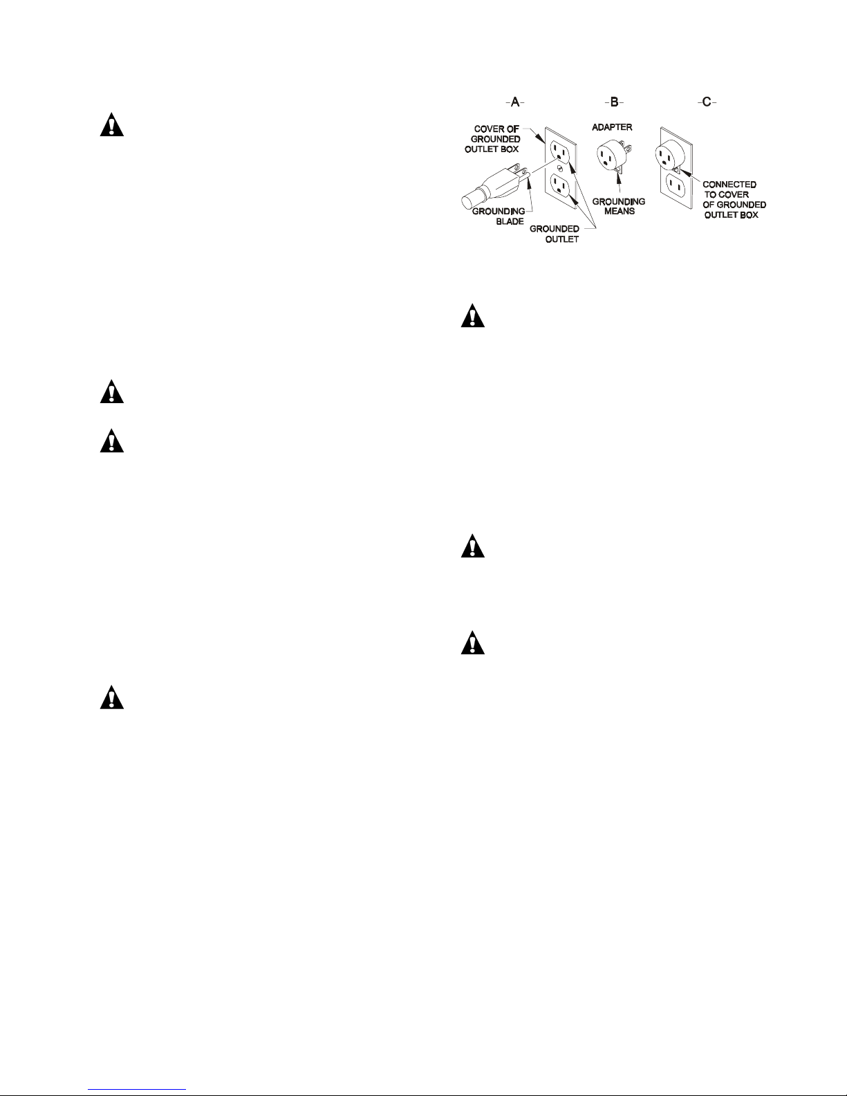
This battery charger is equipped with a grounding
plug as illustrated in Figure A, for use on a
nominal 120 volt, 60 Hertz circuit. A temporary
adapter, as illustrated in Figures B and C, may be
used if a properly grounded outlet is not available.
The temporary adapter should be used only until a
properly grounded outlet can be installed by a
qualified electrician. The green-colored rigid ear
extending from the adapter must be connected to
a permanent ground such as a properly grounded
outlet box.
GROUNDING METHODS
NOTE: Use of an adapter screw as shown in
Figures B and C is not permitted in
Canada.
DANGER: BEFORE USING THE ADAPTER
AS ILLUSTRATED, BE CERTAIN THAT THE
CENTER SCREW OF THE OUTLET PLATE IS
GROUNDED.
NORMAL OPERATION
Instructions printed on cover of charger are for
daily reference.
1. Connect the power supply cord to a properly
grounded, 120 volt, 60 Hertz single-phase
outlet. The RED AC "ON" indicator will glow,
indicating AC power is present.
CAUTION: MAKE SURE THE BATTERY
PACK IS A 24-VOLT, 12-CELL, SERIES
CONNECTED, 150-225 AMP-HOUR (6 HR.
RATE), RECHARGEABLE DEEP-CYCLE
BATTERY SYSTEM.
DANGER: TO PREVENT ELECTRIC
SHOCK, DO NOT TOUCH BATTERY
TERMINALS. MAKE SURE ALL ELECTRICAL
CONNECTORS THAT ARE CRACKED,
CORRODED OR DO NOT MAKE ADEQUATE
ELECTRICAL CONTACT ARE REPLACED
IMMEDIATELY. USE OF A DAMAGED OR
DEFECTIVE CONNECTOR MAY RESULT IN A
RISK OF OVERHEATING OR ELECTRIC
SHOCK.
2. The ammeter needle may bounce initially and
the transformer should hum slightly.
3. Charger will turn ON one to three (1-3)
seconds after completion of the last of the
above actions, and the charger ammeter will
indicate initial charge current.
Operating Instructions 2 01825E
Page 3

WARNING: LEAD-ACID BATTERIES
GENERATE GASES WHICH CAN BE
EXPLOSIVE. IF THE CHARGE CYCLE MUST
BE INTERRUPTED, PRESS THE START/STOP
SWITCH TO STOP THE CHARGER, AND
DISCONNECT THE CHARGER POWER
SUPPLY CORD. KEEP SPARKS, FLAME, AND
SMOKING MATERIALS AWAY FROM
BATTERIES.
WARNING: ALWAYS SHIELD EYES WHEN
WORKING NEAR BATTERIES. DO NOT PUT
WRENCHES OR OTHER METAL OBJECTS
ACROSS BATTERY TERMINALS OR BATTERY
TOP. ARCING OR EXPLOSION OF THE
BATTERY CAN RESULT!
4. Monitor ammeter for correct initial charge rate.
Correct initial charge rate should be between
19 and 21 amps. As the battery reaches
approximately 70% of full charge, the charge
rate gradually decreases to a reading
determined by the condition of the batteries as
stated below.
Replaceable Electrolyte Deep Cycle Battery
With healthy batteries, the charging current
will decrease to between 8 and 10 amps and
remain until the charger turns off. As
replaceable electrolyte deep cycle batteries
lose capacity, the charge rate may no longer
decrease to this reading. The charger will still
determine when the batteries are as charged
as they are capable of being and will turn off.
When battery capacity has decreased to
where the charger is no longer able to taper
down to less than 10 amps, or the batteries
will no longer perform as desired, they should
be replaced.
Charger is equipped with a temperature
sensor which automatically turns charger off if
it overheats. Should charger turn off before
batteries are fully charged, check to be sure all
ventilation openings are free from obstruc-
tions. After charger cools down to a safe
temperature, it will automatically restart. If
charger repeatedly overheats, refer to a
qualified service agent.
5. If the charge needs to be stopped temporarily,
press the STOP/START switch to stop the
charger. To resume the charge, press the
STOP/START switch once again.
6. Charger turns off automatically when batteries
are fully charged. Charge time varies with
battery size and depth of discharge. Allow 8
hours for normal charging. Larger batteries
(greater than 225 ampere-hours) or severely
discharged batteries may require up to 18
hours to be properly charged. If the charger
operates up to 18 hours and is unable to fully
charge the batteries, an internal timer turns
the charger off.
7. After the charger has turned off, as indicated
by the ammeter reading to drop to zero (Note:
the RED light will glow until the AC power is
removed), disconnect AC cord.
WARNING: IF THE CHARGE CYCLE MUST
BE INTERRUPTED, FIRST PRESS THE STOP/
START SWITCH, THEN DISCONNECT AC
CORD. KEEP SPARKS, FLAME, AND
SMOKING MATERIALS AWAY FROM
BATTERIES. NO SMOKING.
WARNING: DO NOT LEAVE THE POWER
SUPPLY CORD PLUGGED IN WHILE
UNATTENDED FOR MORE THAN TWO (2)
DAYS. SEVERE OVERCHARGING AND
DAMAGE TO THE BATTERIES MAY RESULT IF
THE CHARGER DOES NOT TURN OFF.
BATTERY STORAGE MAINTENANCE
When the equipment is not in use, charge the
batteries once each week.
TROUBLESHOOTING GUIDE
CAUTION: DO NOT OPERATE THE
CHARGER IF IT IS DAMAGED OR APPEARS
TO BE MALFUNCTIONING. PERSONAL
INJURY OR DAMAGE TO THE CHARGER OR
BATTERIES MAY RESULT. DO NOT
DISASSEMBLE THE CHARGER. TAKE IT TO A
QUALIFIED SERVICE AGENT WHEN SERVICE
OR REPAIR IS REQUIRED. INCORRECT
REASSEMBLY MAY RESULT IN A RISK OF
ELECTRIC SHOCK OR FIRE.
1. If the charger does not turn on, check for one
of the following:
a. Charger is not plugged into a live AC
outlet.
b. Battery connections are wrong (reverse
polarity).
c. Battery is no longer serviceable (voltage
below 2.5 volts for 12 volt system).
2. If the charger turns off before the batteries are
fully charged, it indicates one of the following:
a. The AC power was interrupted during
charge.
b. The battery has been allowed to sulfate.
Charge the battery at least once every
three days when the equipment is lightly
Operating Instructions 3 01825E
Page 4

utilized. Once sulfation is allowed to take
place, it may be partially reduced by
returning, temporarily, to daily charging.
3. A decrease in equipment range where the
battery loses power earlier and earlier in the
day indicates one of the following:
a. The electrolyte level in conventional liquid
electrolyte lead-acid batteries was allowed
to drop below the top of the battery plates.
Add distilled water to just cover the top of
the plates immediately upon discovery and
fill to the proper level with distilled water at
the completion of the very next charge
cycle. Battery capacity lost in this manner
is permanent and is not recovered with
additional charge cycles.
b. Use of the equipment before the batteries
have been fully charged and the charger
turns off. This shortens battery life and
hastens the onset of reduced daily range.
Battery capacity lost in this manner is
permanent and is not recovered with
additional charge cycles.
c. This is the normal wearout process for all
types of deep-cycle motive power
batteries.
4. The charger runs 18 hours before turning off.
This indicates one of the following:
a. Batteries larger than 225 amp-hour
capacity (6 hr. rate) can require more than
18 hours to charge.
b. New batteries (5 cycles or less) can
require more than 18 hours to charge.
5. The charge rate remains at 20 amps. A
battery system fault exists if the charger does
not decrease below 20 amps. This is caused
when the battery system voltage remains too
low. Measure the battery system voltage
while charging. If the charging voltage does
not increase to 2.3 volts per cell (13.6 VDC for
6 cell 12 volt systems), the battery system
voltage is too low, failed or incorrect and must
be corrected before using the charger.
PROPER CARE OF MOTIVE POWER
BATTERIES
Motive power batteries are subjected to severe
deep cycle duty on a daily basis. Although these
batteries are designed to withstand such duty, the
following precautions must be observed to obtain
good performance and maximum cycle life.
CAUTION: ALWAYS WEAR PROTECTIVE
EYE SHIELDS AND CLOTHING WHEN
WORKING WITH BATTERIES. BATTERIES
CONTAIN ACIDS WHICH CAN CAUSE BODILY
HARM. DO NOT PUT WRENCHES OR OTHER
METAL OBJECTS ACROSS THE BATTERY
TERMINAL OR BATTERY TOP. ARCING OR
EXPLOSION OF THE BATTERY CAN RESULT.
1. When installing new batteries, be sure the
polarity of each battery and overall battery
pack is correct. Due to the electrical
characteristics of this charger, it is possible to
improperly hook up the batteries and not blow
the fuse when charging. Battery and/or
charger damage can result.
2. Always observe the following personal safety
precautions when working with lead acid
batteries:
a. Someone should be within range of your
voice or close enough to come to your aid
when you work near a battery.
b. Have plenty of fresh water and soap
nearby in case battery acid contacts skin,
clothing or eyes.
c. Wear complete eye protection and
clothing protection. Avoid touching eyes
while working near battery.
d. If battery acid contacts skin or clothing,
wash immediately with soap and water. If
acid enters eye, immediately flood eye
with running cold water for at least 10
minutes and get medical attention
immediately.
e. NEVER smoke or allow a spark or flame in
vicinity of batteries.
f. Be extra cautious to reduce risk of
dropping a metal tool onto battery. It
might spark or short-circuit battery or other
electrical part that may cause explosion.
g. Remove personal metal items such as
rings, bracelets, necklaces and watches
when working with a lead acid battery. A
lead acid battery can produce a shortcircuit current high enough to weld a ring
or the like to metal, causing a severe burn.
h. NEVER charge a frozen battery.
DANGER: TO REDUCE RISK OF
ELECTRIC SHOCK, ALWAYS DISCONNECT
THE AC SUPPLY CORD FROM ITS OUTLET
BEFORE ATTEMPTING ANY MAINTENANCE
OR CLEANING OF THE BATTERY.
3. New batteries should be given a full charge
before their first use because it is difficult to
know how long batteries have been stored.
4. Limit use of new batteries for first 5 cycles.
New batteries are not capable of their rated
Operating Instructions 4 01825E
Page 5

output until they have been discharged a
number of times.
5. Do not excessively discharge batteries.
Excessive discharge can cause polarity
reversal of individual cells resulting in
complete failure shortly thereafter. Limited
use of new batteries will minimize the chance
of cell reversal.
6. CHECK THE LEVEL OF THE ELECTROLYTE
IN CONVENTIONAL LIQUID ELECTROLYTE
ACID BATTERIES MONTHLY. MAINTAIN
THE PROPER ELECTROLYTE LEVEL BY
ADDING DISTILLED OR PURIFIED WATER
WHEN NECESSARY. Electrolyte levels lower
during discharge and rise during charge.
Therefore, it is mandatory that water be added
to cells ONLY when they are fully charged; do
not overfill. Old batteries require more
frequent additions of water than do new
batteries.
Operating Instructions 5 01825E
Page 6

WIRING DIAGRAM
PARTS LIST FOR MODEL 26340L
TYPE 24EL20-4ET 120 VAC / 60 HZ
PART NO. QTY. DESCRIPTION
28516S 1 CASE ASSEMBLY
27317S 1 AMMETER
26769S 1 SCR ASSEMBLY
27706S 1 ELECTRONIC TIMER
27784S 1 CONTROL CABLE ASSEMBLY
26112S 1 CORDSET, AC
03837S 1 FUSE HOLDER
16681S 2 FUSE, DC, 25 AMP
15029S 1 FUSE, AC, 12 AMP, MDA-12
18696S 1 SHUNT, ELECTRONIC
26006S 1 INDICATOR, ASSEMBLY
26007S 1 SWITCH, ASSEMBLY
28311S 1 SOLENOID ASSEMBLY
28517S 1 BATTERY CABLE ASSEMBLY
28518S 1 VEHICLE CABLE ASSEMBLY
02028S 1 BUSHING
28519S 1 TRANSFORMER #2
28521S 1 TRANSFORMER #1
02008S 4 BUSHING
Operating Instructions 6 01825E
 Loading...