

Page 1
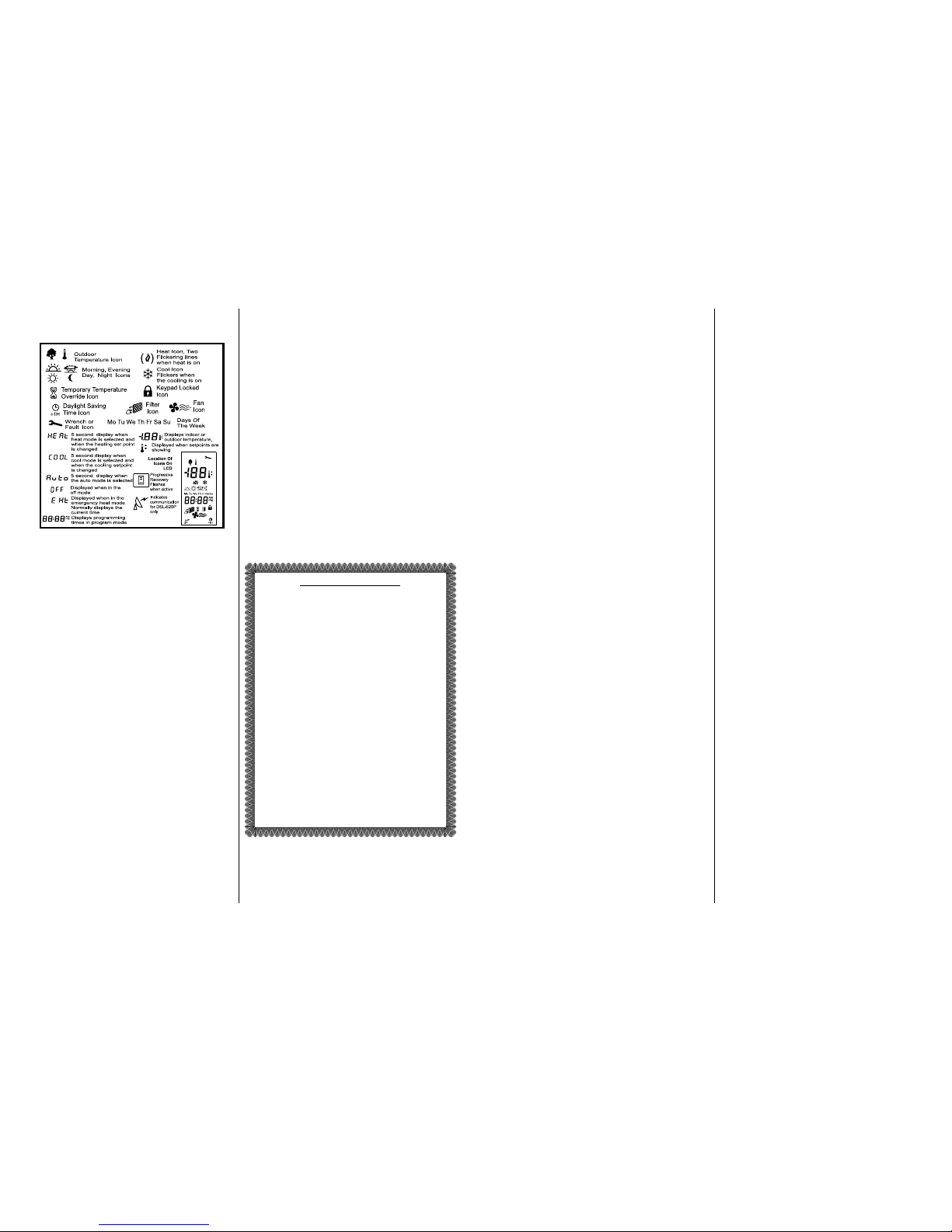
DESCRIPTION OF ICONS
Display icons vary according to the model. Your thermostat may not display all of the icons shown.
DIP SWITCH OPTIONS AND FUNCTIONS
Positioning the DIP switches in either the ON or OFF position
enables you to choose between two different options. The DIP
switches are located on the interior of your thermostat and may
be accessed by following the procedure for removing the thermostat from the subbase. The following list describes your DIP
switch options.
1. 2 Events or 4 Events You may select either a 2- or 4-event
schedule: 2 events include Day and Night; 4 events include
Morning, Day, Evening, and Night.
2. Smart Fan " With the Smart Fan switch in the ON position
and the fan selected, the thermostat will keep the fan running
continuously during the occupied programs and automatically
cycle the fan with a call for heating or cooling during the unoccupied program. (The unoccupied program is the Night event.)
3. 2-Minute or 4-Minute On Times This option allows you to run
the equipment for either a 2- or 4-minute minimum on and off
time.
4. Keypad Lock # In the ON position, locks out all buttons
except the OUTDOOR button.
5. Plenum Fan Switch In the OFF position, the fan comes on
immediately with a call for heat. In the ON position, the fan is controlled by the equipment (plenum switch control).
6. Single or Multi-Stage Set to OFF for 1 compressor stage of
heating or cooling (single stage) or ON for equipment with 2 compressor stages of heating and/or cooling (multi-stage).
7. LED and Filter Icon In the ON position the display will show
the filter icon when the left LED is energized.
8. LED and Wrench Icon In the ON position the display will show
the wrench icon when the right LED is energized.
SPECIFICATIONS
Rated Voltage 18-30 VAC, 24 nominal
Rated A.C. 0.050 Amps to 0.75 Amps continuous
Current per output with surges to 3 Amps Max.
Rated D.C. 0 Amps to 0.75 Amps continuous
Current per output with surges to 3 Amps Max.
Control Heating: 38° to 88°F in 1° Steps
Range 5° to 30°C in 1° Steps
Cooling: 60° to 108°F in 1° Steps
16° to 40°C in 1° Steps
Thermostat
Measurement Range 28° to 124°F or 0° to 48°C
O.D.T. Displayed
Range -50° to 119°F or -48° to 47°C
Control Accuracy ±0.5°C at 20°C, ±1°F at 68°F
Minimum (between heating and cooling)
Deadband 2°F or 1°C
Note: This thermostat contains electronic circuitry replacing the conventional
mechanical anticipator.
Two (2) Year Limited Warranty
The manufacturer warrants to the original purchaser that its product and component parts will be free from defects in workmanship
and materials for a period of Two (2) year from the date of purchase. Return to the original point of purchase for replacement of
your product.
Warranty Limitations
This warranty begins at date of final purchase.
Warranty is void if:
The date code is defaced or removed.
The product has a defect or damage due to product alteration, connection to an improper electrical supply, shipping and handling,
accident, fire, flood, lightning, or other conditions beyond the control of the manufacturer.
The product is not installed according to the manufacturer’s instructions and specifications.
The product has been installed near sources of electromagnetic
interference (EMI) such as arcing relay contacts.
Owner’s Responsibility
Provide proof of purchase.
Provide normal care and maintenance.
Pay for freight, labor and travel.
Pay for service calls related to product installation.
Return any defective product.
In no event shall the manufacturer be liable for incidental or consequential damages.
This warranty gives you specific legal rights and you may have others
which vary by state and/or province. For example, some states
and/or provinces do not allow the exclusion or limitation of incidental
or consequential damages, so this exclusion may not apply to you.
The manufacturer’s continuing commitment to quality products may
require a change in specifications without notice.
This equipment, if installed in strict accordance with the manufacturer’s instructions, complies with the limits for a Class B computing
device pursuant to Subpart J of Part 15 of FCC rules.
DIP Switch
DIP Switch OFF
DIP Switch ON
1
2
3
4
5
6
7
8
4 events per day
Smart Fan disable
4 minute minimum ON
Keypad unlock
Fan with heat call
Single stage
LED #1 + No icon
LED #2 + No icon
2 events per day
Smart Fan enable
2 minute minimum ON
Keypad lock
Fan with plenum switch
Multi-stage
LED #1 + Filter
✪ icon
LED #2 + Fault
✩ icon
NEW AND IMPROVED FEATURES
Your new electronic programmable thermostat has been made even
better by the introduction of several new and improved features.
Building on its reputation for efficient and dependable operation,
your thermostat now offers the following list of enhancements.
Progressive Recovery (available on programmable models)
Selecting progressive recovery on your programmable thermostat
causes the thermostat to anticipate the programmed setpoint
change, thus allowing the climate-controlled area to reach the desired
setpoint when required. The progressive recovery option is selected
by pressing the FAN and PROGRAM buttons simultaneously.
Thermostat and Sensor Calibration
Release 3 provides easy calibration of the thermostat and remote
sensors. Simply press and hold the FAN button for 10 seconds
and adjust with the up or down buttons.
Programming Revert Time Extended
The programming revert time has been extended to 2 minutes.
Push Button Auto Repeat
Programming is easier with the push button auto repeat feature.
Extended Backup Time
The power failure backup time has been increased to 2 hours.
BUTTON FUNCTIONS
CLOCK Press to set current day, hour and minute
SET TEMP Press to set the heating and cooling setpoints
PROGRAM Press to set program days and start times. Press
simultaneously with the FAN button to select progressive recovery.
HOLD Press to hold the current setting. The program will
hold indefinitely or until RESUME is pressed.
OUTDOOR Press to display the outdoor temperature (optional)
MODE Press to select cool only, heat only, auto (cool and
heat), or off
FAN Press for continuous fan or auto fan
RESUME Press to exit the hold or override program or when
programming is complete.
✞!✟ Press down or up buttons during programming and
overrides to lower or raise setpoints and change the
day and time
Selecting Fahrenheit or Celsius Display
Simultaneously press the ✟ and ✞ buttons to switch between
Fahrenheit and Celsius.
Changing the Clock from 12 to 24 Hour
To change the time indicated from 12 hour to 24 hour, press and
release the CLOCK button, then press the MODE button.
Power Outages/Failures During Regular Program Schedule
Should your power fail at any time during the regular program, the
thermostat will maintain the clock internally for up to 2 hours. If the
power has not been restored during this time, the clock will stop.
When the power is restored, the thermostat clock defaults to a
flashing 12:00 AM. The thermostat will be held in the Night pro-
gram until the user resets the clock. The thermostat will display
AC when the 24 VAC is not powered. One of the unique features
of your thermostat is that no battery is required to maintain your
selected setpoints in the event of a power loss, since the memory
is unaffected by power failures of any duration. There is no reason
to reprogram the setpoint temperatures or start times since the
thermostat will retain these program parameters automatically.
UNDERSTANDING 7 DAY PROGRAMMING
It is recommended that you read and understand these
instructions before you attempt to program your
thermostat.
Programming your thermostat involves selecting the temperature
you want in your home and selecting the time you want it to be
that temperature.
Each time schedule is known as an event. An event ends at the
same time that the next event begins so only a starting time for
each event is required.
Your thermostat allows you to choose between a 2-event (Day
and Night) or 4-event schedule. This is a DIP switch selectable
option. For a more detailed description of event options refer to
“DIP Switch Options and Functions.”
Event = Morning ✣, Day ✥, Evening ✤, Night ✠
Event Time = the time the event starts
Event Setpoint = the temperature set during the event;
each event can have only one heat
and one cool setpoint
The Morning event is typically when you wake up and is the first
event of the day. The Day event is normally set when you leave
for work. The Evening event is usually set for when you arrive
home. The Night event is set when you go to bed.
Each event will have two (2) temperatures: 1 heating temperature
and 1 cooling temperature. The cooling temperature must be at
least 2 degrees F / 1degrees C higher than the heating temperature.
The event setpoints are programmed once for all seven (7) days.
The thermostat allows a different program for each day of the
week. Complete the chart labeled “Set Your Personal Schedule”
with your desired temperatures and time schedules before beginning programming.
To exit programming at any time, press and release the RESUME
button, or 2 minutes after pressing the last button the display will
automatically change to the normal display.
PROGRAMMING THE THERMOSTAT
Setting the Current Day and Time
1. Press and release the CLOCK button. The display will flash MO
for Monday.
2. Press the ✞ or ✟ button until the current day appears on the
display.
3. Press the CLOCK button to select the hour. The display will
flash 12:
4. Press the ✞ or ✟ button until the current hour appears on the
display. Be sure the AM or PM corresponds to the proper time.
5. Press the CLOCK button once again to select the minutes. The
display will flash :00.
6. Press the ✞ or ✟ button until the current minutes appear on
the display.
7. Press RESUME or wait for the regular display to appear.
You have now set the current day and time on the thermostat and
are ready to begin programming the details of the events and setpoints.
Program the Events
The event programming procedure that follows assumes the thermostat is in the AUTO mode and set for 4 events per day (DIP
switch #1 set in the OFF position). If you require only 2 events per
day you may change this option by setting DIP switch #1 to the
ON position. Refer to “DIP Switch Options and Functions” for
details. The programming procedure remains the same except
Operating Instructions
enerstat SMS-1 7 Day Programmable Thermostat
Multistage Auto Changeover 2 Heat/2 Cool
Model SMS-1
111-103C 5/2000
Page 2
that you will not have the option of programming for the Morning
or Evening events.
1. Press and release the SET TEMP button.
2. You will see a Morning ✣ or Day ✥ icon;
* a heating , or cooling ☛ icon;
* a flashing setpoint ✸✾ (temperature).
3. Select the desired setpoint by pressing the ✞ or ✟ button.
4. Press and release the SET TEMP button to move to the next
event. Continue until all Morning, Day, Evening and Night
events and heating and/or cooling setpoints are programmed.
Setting the Event Start Times
1. Press and release the PROGRAM button.
2. You will see a Morning ✣ heating , or cooling ☛ icon,
setpoint ✸✾, flashing MO (Monday) or current day of the week.
3. Select the desired weekday by pressing the ✞ or ✟ button.
4. Press and release the PROGRAM button.
5. Select the desired hour by pressing the ✞ or ✟ button.
6. Press and release the PROGRAM button.
7. Select the desired minute (if necessary) by pressing the ✞ or
✟ button (in increments of 10 minutes).
8. Press and release the PROGRAM button to move to the next
event.
9. Repeat the process until all of the desired event start times
have been programmed.
Copy the Events to Other Days
Once you have gone through the programming procedure for
Monday, ending at the Night ✠ event, the word COPY will appear.
You may choose to copy the 4 event start times to other days of
the week. Press the ✞ button to display all the days of the week.
Press the ✟ button to select the consecutive days of the week
that you want the events to apply to. Press the PROGRAM button
to do the copy or press the RESUME button to return to the normal display.
Individual Days
If certain days of the week require different event starting times,
follow the procedure below.
1. Press and release the PROGRAM button.
2. Press the ✞ or ✟ button to advance the day indicator to the
desired day.
3. Press and release the PROGRAM button to change the event
hours and minutes to the desired starting times as in “Setting
the Event Start Times.”
4. Press the RESUME button to return to the normal display.
Skipping an Event (2 Methods)
Your personal schedule may not require the use of all 4 events on
a weekday. For example, if you wish to go from the Day event
directly to the Night event and skip over the Evening event, there
are 2 methods you can use:
A. Press and release the PROGRAM button until you come to the
day and event hour on the day that you wish to skip.
A) Press and hold down the PROGRAM button and at the same
time press and release the MODE button. In the time display
area you will see _ _ : _ _ indicating that the event is skipped.
B. If any two or more events have the same start time, the latest
event in the day has priority and therefore uses its setpoints.
Reviewing Scheduled Times
To review the program schedule, repeatedly press and release the
PROGRAM button. Each of the scheduled events is displayed
starting with the temperature, day, hour and minute for each day
of the week. To cancel your review, press the RESUME button, or
simply wait 2 minutes for the thermostat to resume the display
automatically.
Reviewing Programmed Temperatures
To review your programmed temperatures, repeatedly press the
SET TEMP button. The display will change to show the mode,
event, and the setpoint selected.
Viewing the Outdoor Temperature (Option)
If your thermostat has been installed with an electronic outdoor
remote sensor ( SLIDS), you may view the outdoor temperature simply by
pressing the OUTDOOR button. Upon releasing the button, the
thermostat will once again display the indoor temperature.
Temporary Temperature Override
To temporarily change the scheduled setpoint during an event
without affecting the program, press the ✞ or ✟ buttons to lower
or raise the setpoints. The new setpoint will be retained for 3
hours and will not affect the programming schedule. You may
return to the regular program schedule by pressing the RESUME
button.
Temporary Temperature Override with Keypad Locked
(The keypad may be locked to prevent tampering by selecting the
ON position of DIP switch #4.)
With the keypad locked to prevent tampering you may temporarily
adjust the setpoint by ±3°C or ±6°F of the programmed Morning
(4 event) or Day (2 event) setpoint without affecting the regular
program. Press the ✞ or ✟ button to raise or lower the setpoint
for a 1 hour period. This override may not be cancelled by pressing the RESUME button.
Constant Override
To maintain a temperature setting for an indefinite period of time,
press the HOLD button. The word HOLD will appear on the LCD.
The current scheduled setpoint will be maintained. To select a different setpoint, press the ✞ or ✟ button to raise or lower it. The
last setpoint selected (scheduled or new) will be maintained continuously until the RESUME button is pressed.
Off Mode
To turn off the heating or cooling system, press the MODE button
until the word OFF appears on the LCD. It will remain displayed
until the mode is changed. The OFF mode prevents the system
from being energized. Avoid using the OFF mode during extremely cold weather to prevent damage to the equipment from freezing.
Auto Changeover Mode
To set the thermostat to automatically switch from heating to
cooling, press the MODE button until the word AUTO and both
the heating , and cooling ☛ icons appear on the LCD. The thermostat energizes the heating or cooling system based on the
temperatures established for both modes.
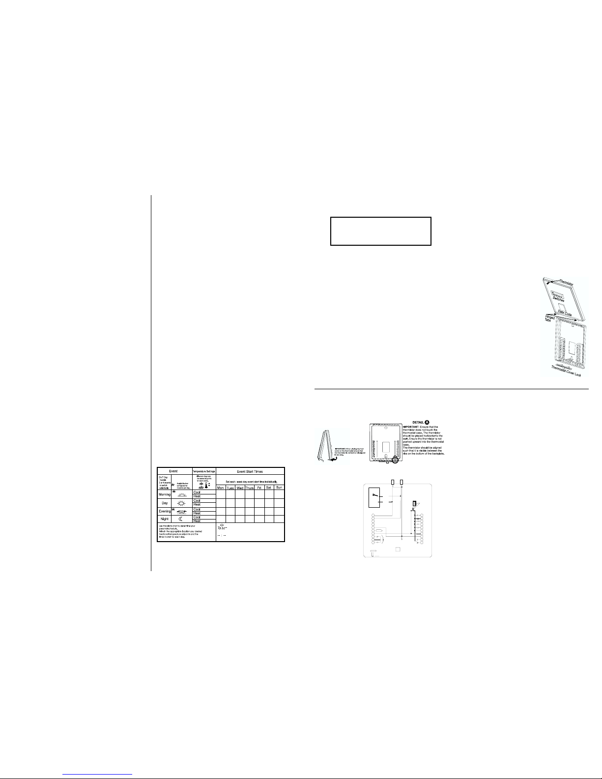
SET YOUR PERSONAL SCHEDULE
This blank chart is for your use. Start by selecting your heating and cooling temperature
setpoints. Determine the time you want the temperatures to be active. Write the desired
times in the appropriate box. Typically, programming would begin on Monday, allowing
you to copy the Monday schedule to the consecutive days of the week.
To skip a particular event for a particular day,
select the day and event, hold the PROGRAM
button in at the hour or minute section, then press
the MODE button. This will put four dashes in the
hour and minute section.
INSTALLATION INSTRUCTIONS
Location
Mount the thermostat on an inside wall in a frequently occupied
area of the building. Its position must be at least 18" (46cm) from
any outside wall, and approximately 5' (1.5m) above the floor in a
location with freely circulating air of average temperature. Avoid
the following locations:
- behind doors or in cor ners where circulating air is unavailable
- where radiant heat from appliances might affect control operation
- on an outside wall or door, in direct sunlight or in stairwells
- adjacent to, or in line with, conditioned air discharge grilles
- where operation may be affected by steam or water pipes or
warm air stacks in an adjacent partition space, or by an unheated/uncooled area behind the thermostat
- where its operation is affected by supply air of an adjacent unit
- near electrical interference (e.g., arcing relay contacts)
Removing the Thermostat from the Subbase
1. Insert a flat blade screwdriver or coin
1
⁄8" (3mm) into the slot located in
the bottom center of the thermostat case and twist
1
⁄4turn.
When you feel or hear a click, grasp the case from the bottom
two corners and separate from the subbase. Some models
require more force than others when separating.
2. Swing the thermostat out from the bottom.
3. Lift the thermostat up and off the subbase.
4. Place the rectangular opening in the subbase over the equipment control wires protruding from the wall and, using the subbase as a template, mark the location of the two mounting holes.
(Exact vertical mounting is necessary only for appearance.)
5. Use supplied anchors and screws for mounting on drywall or
CAUTION
THIS DEVICE SHOULD BE INSTALLED BY A
QUALIFIED TECHNICIAN WITH DUE REGARD
FOR SAFETY, AS IMPROPER INSTALLATION
COULD RESULT IN A HAZARDOUS CONDITION
plaster; drill two 3⁄16" (5mm) diameter holes at marked locations;
use a hammer to tap nylon anchors in flush to the wall surface
and fasten subbase using supplied screws. (Do not overtighten!)
6. Connect the system wires to the thermostat terminals as shown
in the wiring diagrams. Carefully dress the wires so that any
excess is pushed back into the wall cavity or junction box.
Ensure that wires are flush to the plastic subbase. The access
hole should be sealed or stuffed to prevent drafts from affecting
the thermostat.
7. Before the thermostat is reinstalled on the subbase, install the
optional clock/timer, indoor remote sensor and outdoor remote
sensor, if used. Refer to installation instructions supplied with
each. Also check DIP switch positions on the back of thermostat.
Replacing the Thermostat on Subbase
1. Position the thermostat on the hinged
tabs at the top of the subbase.
2. Gently swing the thermostat down and
press on the bottom center until it
snaps into place.
Thermostat Cover Lock
Insert the plastic lock piece into the bottom of the mounted base. The ends of the
lock piece fit snugly under the lock pins
extending from the bottom of the mounted
base. The tab in the middle of the lock
piece extends down from the base.
To release the locking mechanism, press
the lock piece up and into the base while
gently prying open.
Thermistor location Instructions
When placing the front cover on the thermostat, ensure the thermistor is not bent
or misaligned. Ensure that the thermistor
does not touch the thermostat case. The
thermistor should be placed horizontal to the wall.
Thermistor location Instructions (cont’d)
Ensure the thermistor is not pushed upward into the case. The
thermistor should be aligned so it is visible between the ribs on
the bottom of the subbase.
WIRING DIAGRAM
This thermostat may
be used with 24V DC.
The negative side of
the DC supply must
be wired to the 24V(c)
terminal. Note: If the
24V(c) is not available
from the equipment,
the jumper may be
removed and a separate 24V transformer
must then be used to
power the thermostat.
To remove jumper
(labeled JP1) from the
printed circuit board,
pull straight out.
TERMINAL DESIGNATIONS
W2 . . . .Energizes on a call for second stage heating
Y2 . . . .Energizes on a call for second stage cooling
W1 . . . .Energizes on a call for first stage heating
Y1 . . . .Energizes on a call for first stage cooling
G . . . . .Fan is energized with a call for heating or cooling or by
pressing the FAN button
R . . . . .Optional relay output voltage (JP-1 must be removed)
24V . . .24 VAC or DC Active / Hot to power the thermostat
24V(c) . .24 VAC or DC Neutral / Common to power the thermostat
O . . . . .Energizes reversing valve continuously in cooling mode
B . . . . .Energizes the reversing valve continuously in the
heating and off modes
RS2 . . .Use to connect up to 6 (SL-IDS) indoor and/or 1 (SL-ODT)
RS1 outdoor remote sensor/s.
RS+V . .When connected the thermostat will automatically use
the SL-IDS temperature sensor and not its onboard sensor.
Refer to the instructions included with the sensor
NO . . . .NO and common connected during Night mode, default
COM with AC failure, OCC (occupied/unoccupied) relay de-
energized
NC . . . .NC and common connected during Morning, Day and
Evening programs, OCC (occupied/unoccupied) relay
energized
LED1 . .Free status light when energized lights LED1. Also see
Switch 7
LED2 . .Free status light when energized lights LED2. Also see
Switch 8 (Installer should identify what the LEDs are being
used for)
W1
Y1
G
O
B
LED1
LED2
RS2
RS1
OCC
Free Light / LED2 (Right)
Free Light / LED1 (Left)
<
Temperature Sensor
SW 8
SW 7
R
24v
24v(c)
Display
Y2
RS+v
NC
NO
New
R/24v Jumper replaced
with a connector (JP-1).
Remove if thermostat power
is not supplied by equipment.
W2
COM
SMS-1
 Loading...