

Page 1
Page 2

Page 3

1. About this Manual
2. Safety Precautions
3. Features
4. Specications
4.1 Control and Power Supply Unit (CU)
4.2 Delegate (DU) and Chairman (CH) Units
5. System Set-up
5.1 Interconnecting Delegate and Chairman Units
5.2 Connecting up to 150 Units
5.3 Connecting an External Microphone
5.4 Connecting a Wireless Microphone
5.5 Recording / Playing Back the Discussion Audio
5.6 Connecting a PA System | Other External Equipment
5.7 Connecting a Telephone Coupler
5.8 Connecting an Equalizer or Other Eect Devices
5.9 Connecting the AC Power Cord
6. Operation
6.1 System Testing
6.2 Date / Time Setting
6.3 Key Lock
6.4 Counter Operation
6.5 Delegate Unit Operation
6.6 Chairman Unit Operation
6.7 Volume Control of the Delegate and Chairman Units
6.8 CU Internal Speaker and Headphone Volume Control
6.9 Using Headphones on Delegate/ Chairman Microphone Units
6.10 Open Mode
6.11 Time Mode
6.12 Override Mode
6.13 Chairman Only Mode
7. Technical Data
7.1 Electrical and Electro-acoustical Characteristics
7.2 Mechanical Specications
7.3 General Specications
7.4 Pin Conguration
8. Limited Warranty Statement
4
4
5
6
8
10
10
11
11
12
13
14
14
15
16
16
16
17
17
18
19
19
20
20
21
22
22
23
24
24
25
26
Page 4

4
1. About this Manual
Read this user manual carefully before installing and
operating your CS-300 Conference and Discussion System.
Use the product only as described to avoid accidental injury,
damage or hearing impairment. Also, read safety warnings
carefully. Keep this manual for future reference. If you
give this system to someone else, remember to include this
manual.
2. Safety Precautions
• Make all connections before plugging the unit into an AC
power outlet.
• Never connect or disconnect cables or microphone units
with the system turned on. Always turn off the system
before plugging or unplugging microphone units or
cables so as not to damage the system.
• Do not leave the devices in places with high temperatures
or high humidity.
• Do not handle the power cord with wet hands.
• Keep the devices away from re and heat sources.
• Keep the system out of the reach of children.
• The CU must be connected to ground via the power cable
for safety reasons and to ensure the audio performance of
the system.
• Do not open the CU and/or delegate/chairman units. There
are no user serviceable parts inside.
• Before using this product with a pacemaker or other
medical device, consult your physician or the
manufacturer of your pacemaker or other medical device.
• Using this product at a loud volume or over a prolonged
period of time can lead to permanent hearing damage.
• Reduce the volume to its lowest setting before use.
• When using a mobile phone near this product, noise may
be produced, but this is not a malfunction. Keep mobile
phones as far away as possible from the product.
• To clean, be sure to rst switch off and unplug the CU
from the power outlet, then wipe with a dry cloth. When
extremely dirty, use a soft cloth dampened in neutral
detergent. Never use benzene, thinner or
chemically-treated towels, which may damage the
product’s nish.
Page 5

5
3. Features
The innovative Enersound CS-300 Conference and
Discussion System is equipped with a high-quality ECM
capsule, intelligent automatic mixing technology and
integrated acoustic and mechanical design, providing a
turn-key solution and delivering consistently natural,
feedback-free audio performance in any environment.
The CS-300 Conference and Discussion System is ideal for
discussions and meetings of up to 150 people.
A CS-300 Conference and Discussion System consists of:
• (1) Control and power supply unit (CU)
• Maximum of (50) delegate or chairman units
• Peripheral audio and/or telecommunication equipment
The CU (Control Unit) is the core of the discussion system,
which controls the microphones of the chairman and
delegate units as well as the other audio input and output. It
also supplies the power for up to 50 delegate and chairman
units.
The delegate unit enables attendees to participate in a
discussion by speaking through a microphone controlled
by a microphone ON/OFF push-button and listening to the
discussion through the internal loudspeaker or external
headphone.
The chairman unit not only provides the same function
as the delegate unit, but also supports the addition of a
“priority button,” which enables the chairman to control
the discussion by temporarily or permanently overriding
and deactivating all active delegate units.
Page 6
6
4. Specications
4.1 Control and Power Supply Unit (CU)
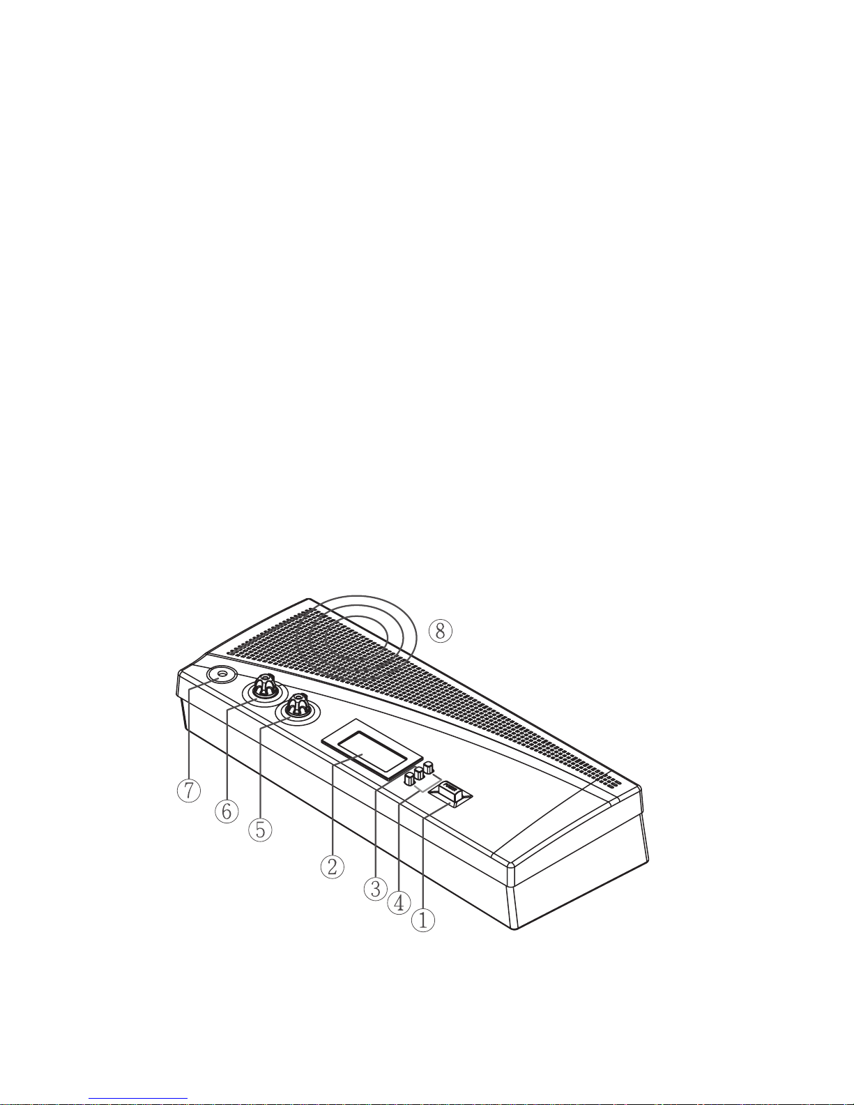
4.1.1 Front Panel
1) Power On/Off switch
2) LCD display: Simultaneously sets and displays mode
status, maximum user number and date.
3) Set button: Press “Set” button to enter setting mode on
the LCD panel.
4) Up & Down buttons: Press “Up” or “Down” to change
settings.
5) Speaker volume control: Controls the internal speaker
volume on all connected chairman and delegate units.
6) Monitor volume control: Controls both speaker and
headphone volumes on the CU.
7) Headphone input: Serves as an alternative way to listen
to the discussion. While the headphone is inserted, the
loudspeaker will be deactivated.
8) Loudspeaker: Allows the user to listen to the discussion
from the control unit
Page 7
7
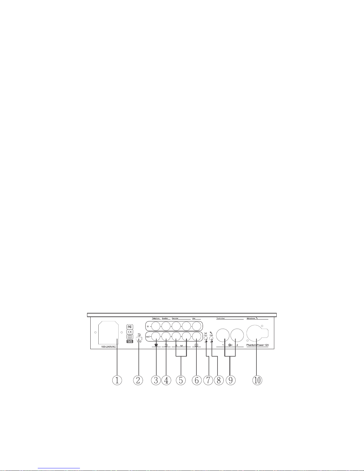
4.1.2 Rear Panel
1) AC power socket
2) Insertion input and output switch: When switching to
“1,” all internal speakers will be muted and switched to
external audio device. This is used in conjunction with 4).
3) Telephone coupler input and output
4) Insertion input and output: Connects to an external audio
equalizer for speech quality improvement.
5) Recorder input and output: Connects to a recorder that
can record and play back the discussion.
6) Line input and output: Connects to a PA system or other
audio devices.
7) Gain control 1: Controls the volume level of recording
input
8) Gain control 2: Controls the volume level of microphone
XLR input.
9) Trunk output 1 and 2: Connect to chairman and delegate
units. Always turn o the CU before connecting or
disconnecting cables or units in these trunks.
10)Microphone XLR input: Connects to an external
microphone or wireless microphone receiver.
Page 8
8
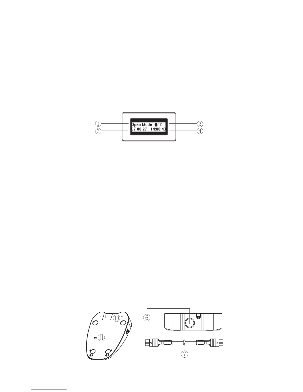
4.1.3 LCD Display
1) Mode status: Shows the discussion mode
2) Maximum number of active microphones: The
maximum number of active delegates can be set between
1 and 4 for open and time modes.
3) Date: While setting the date, “Set” will ash.
4) Time:
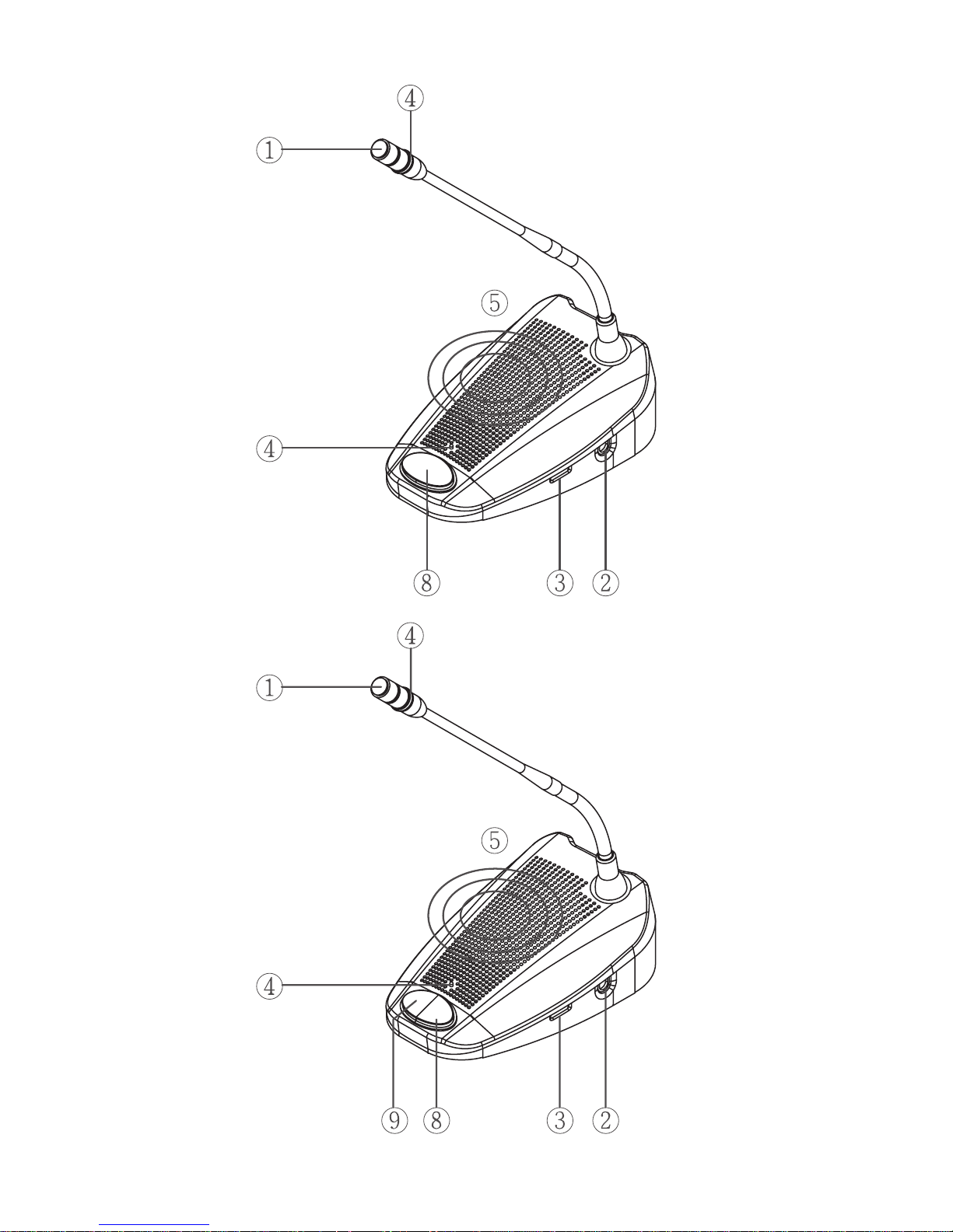
4.2 Delegate and chairman units (see image below
and on next page)
1) Gooseneck microphone
2) Two 3.5mm stereo headphone sockets
3) Rotary volume control: Controls the volume level of the
headphone.
4) Ring light & microphone “On” LED indicator: While
microphone is activated, both indicators will light up.
5) Loudspeaker
6) 7-pole circular female socket
7) 7-pole circular male connection cable
8) Microphone ON/OFF push-button
9) Chairman priority button
10) Priority button and Chime setting switches (See Section
6.6 below)
11) Gooseneck microphone gain control: Adjusts the volume
of the microphones on the chairman and delegate units.
Modifying the gain is not recommended unless it is
necessary for a particular purpose.
A
B
Page 9
9
Delegate unit
Chairman unit
Page 10
10
5. System Set-up
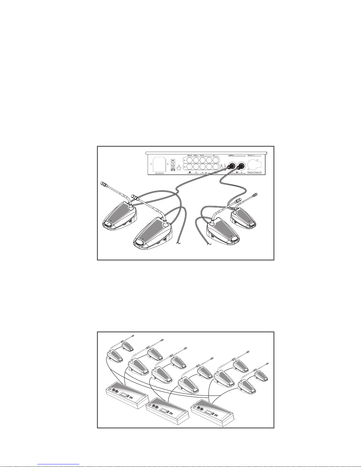
5.1 Interconnecting Delegate and Chairman Units
1) Insert 7-pole circular male connection cable of rst unit
(chairman or delegate units) into the trunk socket on CU.
2) Connect second unit to 7-pole circular female socket of
rst unit.
3) Repeat the above actions for the rest of units. Maximum
connected number of units per trunk socket is 25. (50
per control unit). Maximum total cable length per trunk
should not exceed 100 meters including the 2 m cables
attached to each unit.
5.2 Connecting up to 150 Units
The CS-300 Conference and Discussion System can be used
with up to 150 units by adding a maximum of 2 additional
CUs functioning as power supply units only. The system
is controlled by the master CU. The necessary expansion
boxes and cables for these connections can be provided by
your local dealer.
3...25 3...25
Page 11
11
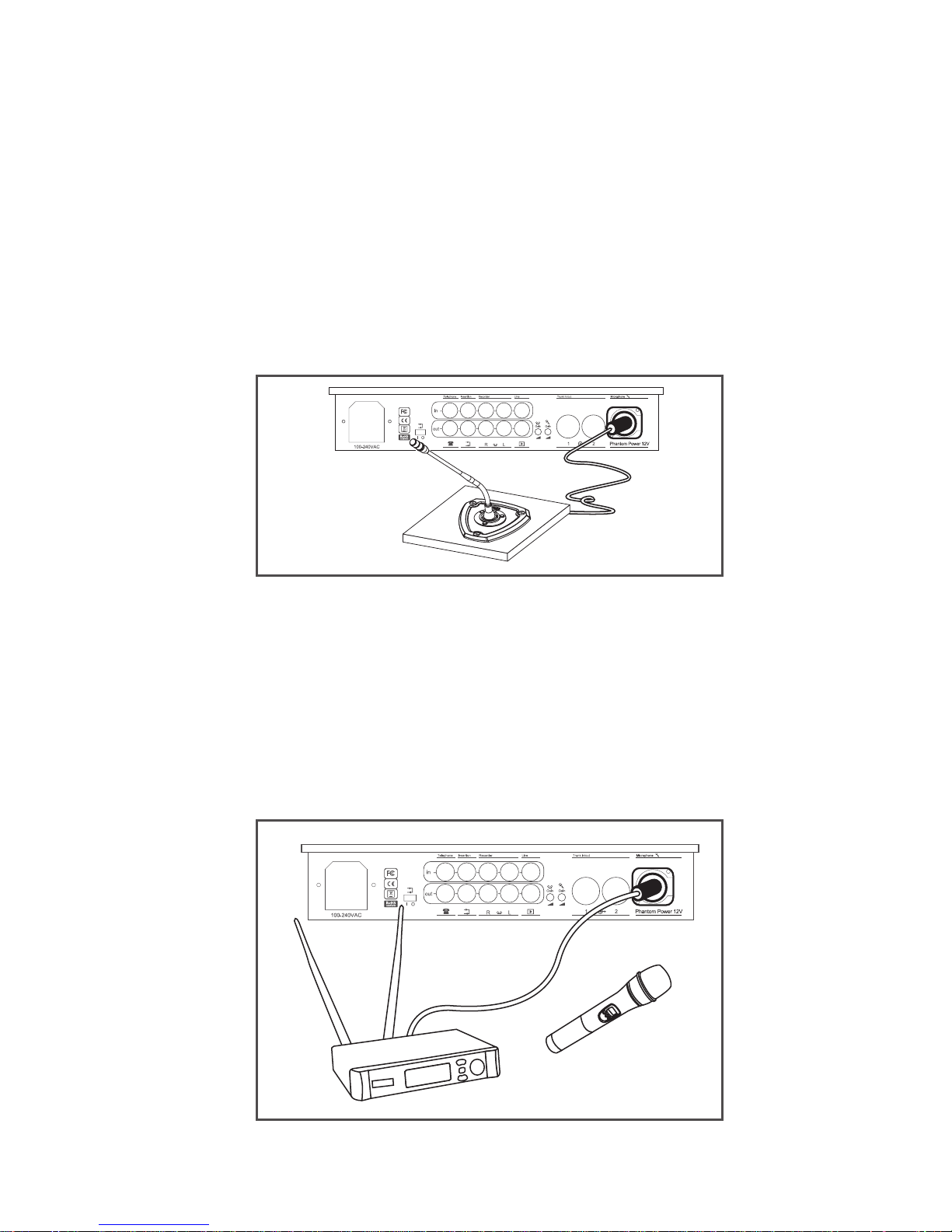
5.3 Connecting an External Microphone
1) Insert an external microphone connector into
microphone XLR input on CU.
2) Adjust the sensitivity by using gain control 2.
Caution: Always use the microphone with
balanced output. The microphone XLR input
provides a 12V phantom power supply.
5.4 Connecting a Wireless Microphone
1) Connect a wireless receiver to microphone XLR input
on CU.
2) Adjust the sensitivity by using gain control 1.
Caution: Always make sure that any device connected
to the XLR microphone input on the control unit can
handle 12V phantom power. Check user manual or
contact manufacturer of equipment to be connected.
Page 12
12
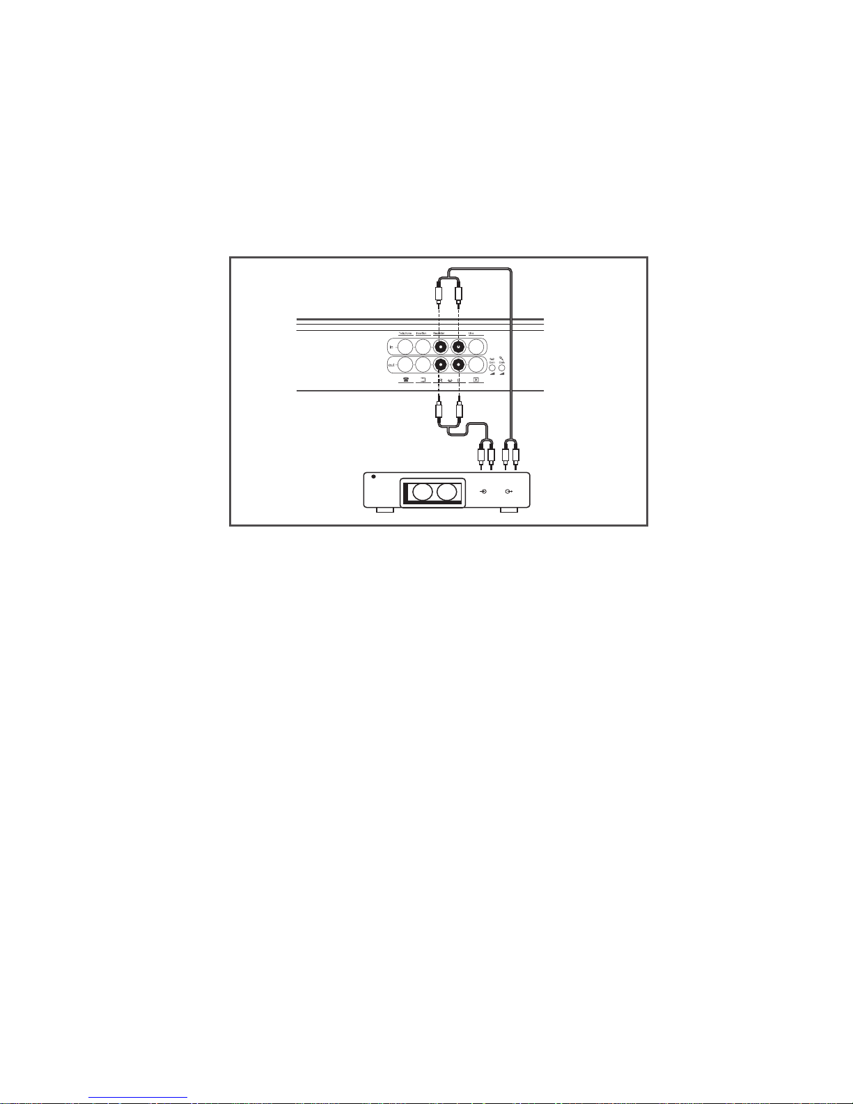
5.5 Recording / Playing Back the Discussion Audio
1) Connect a recorder to the recorder input and output by
using two pairs of RCA cables.
2) Adjust the sensitivity by using gain control 1.
outin
Page 13
13
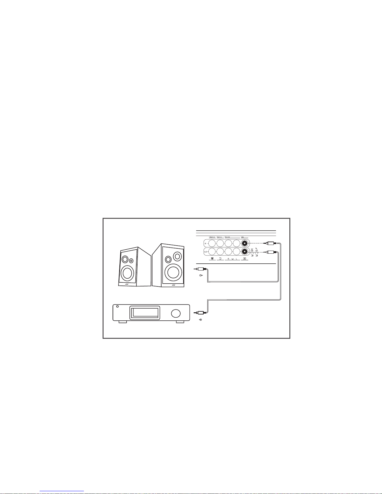
5.6 Connecting a PA System or Other External
Equipment
1) Connect audio sources to the line input using an RCA
cable.
2) Connect a PA system or other devices to the line output
using an RCA cable. Caution: Never connect the control
unit to a microphone input on another device with
phantom power since this can damage the control unit.
For example, if you need to connect the line output on
the CU to the sound mixer of a PA system, always use an
RCA male to ¼ inch plug (6.3 mm plug) or an RCA to
RCA cable to connect into a line input on the mixer. Do
not connect into the microphone input on the mixer since
it may have phantom power activated.
out
in
audio sources
PA system
P A
Page 14
14
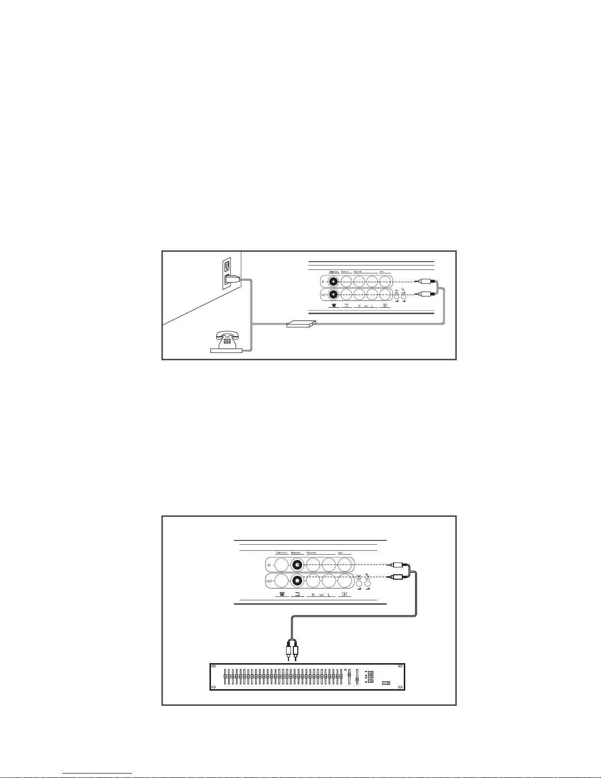
5.7 Connecting a Telephone Coupler
1) Connect the telephone coupler to the telephone input and
output of the CU using a pair of RCA cables.
2) The telephone coupler can further connect to the
telephone wall socket and a telephone.
Caution: Never try to connect a telephone directly to the
CU.
A telephone coupler will provide adequate isolation
between the telephone network and the CU.
5.8 Connecting an Equalizer or Other Effect
Devices
1) Connect an equalizer or other effect devices to the
insertion input and output using one pair of RCA cables.
2) The insertion switch should be in the “1” position for
the audio signal to be processed by equalizers or effect
devices. Switch must be in “0” (loop through) position if
the insertion input and output is not used.
Telephone Coupler
Equalizer
Page 15
15
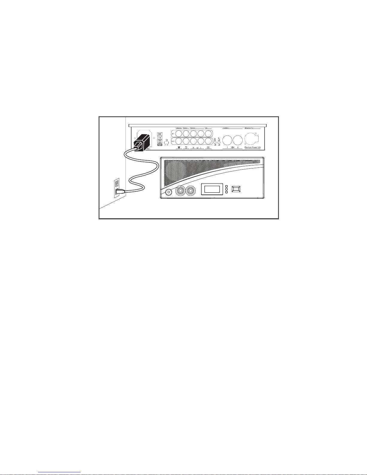
5.9 Connecting the AC Power Cord
1) Using the supplied power cord, connect the CU to the
power outlet.
2) Press the power ON/OFF switch to turn on system. As
soon as the power is on, the LCD Display will light up.
.
Page 16
16
6. Operation
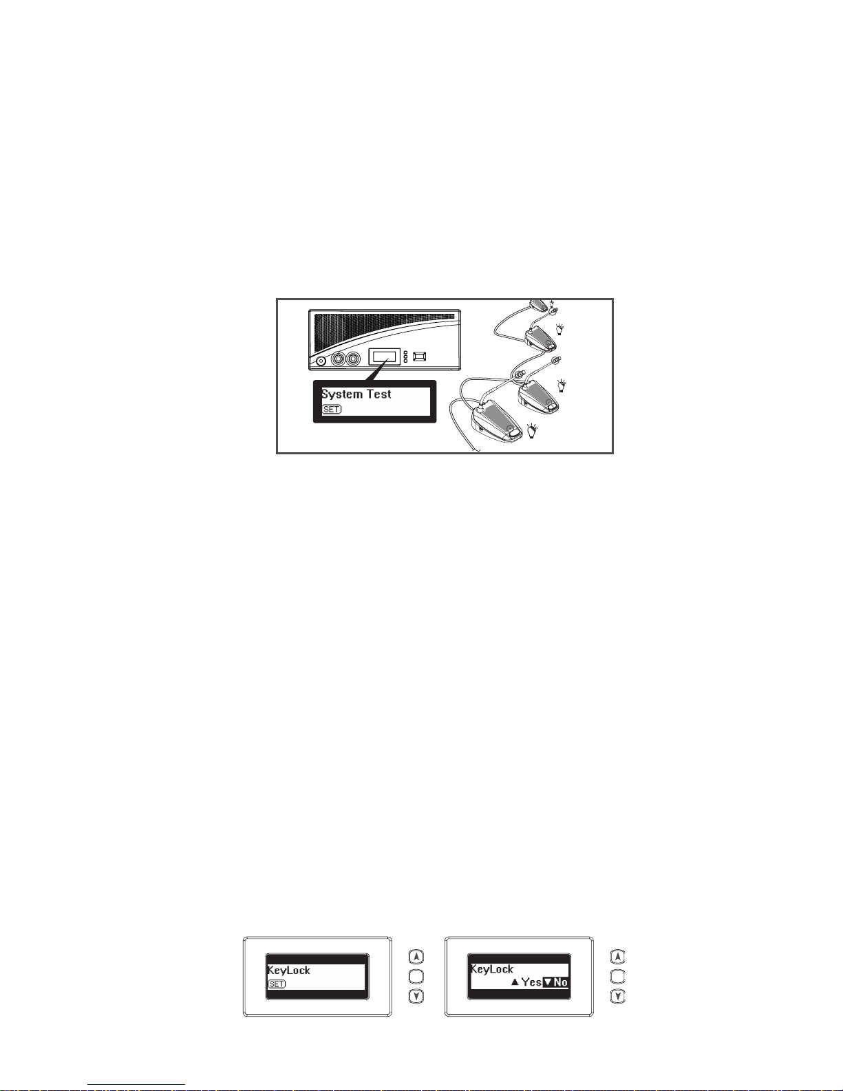
6.1 System Testing
1) Press and hold the “Set” button for 2 seconds and the
“Set” icon will ash.
2) Press the “Up” or “Down” arrow buttons to choose
“System Test” on the Mode Status area of the LCD
display.
3) All connected chairman and delegate units will light up.
If not, check connections. To exit, press the arrow buttons
until you nd “Exit” on the screen and then press “Set.”
6.2 Date / Time Setting
1) Press and hold the “Set” button for 2 seconds and the
“Set” icon will ash.
2) Press the “Up” or “Down” button to choose “Set Date /
Time” on the Mode Status area of the LCD Display.
3) Press “Set” and the “Year” will be highlighted, then press
the “Up” or “Down” arrow to select year.
4) Repeat action 3) to set up “Month,” “Date,” “Hour” and
“Minute.”
5) Press the “Set” button to save the settings and exit.
6.3 Key Lock
1) Press and hold the “Set” button for 2 seconds and
the “Set” icon will ash.
2) Press “Up” or “Down” arrow to choose “Key
Lock” on the Mode Status area of LCD Display
and press “Set.”
3) Then press the “Up” arrow to choose “Yes” to
activate key lock and then press “Set.”
4) All buttons will be deactivated.
5) To unlock, press the “Set” button for 2 seconds and
choose “No” with “Down” arrow and press “Set.”
3...25
SET SET
Page 17
17
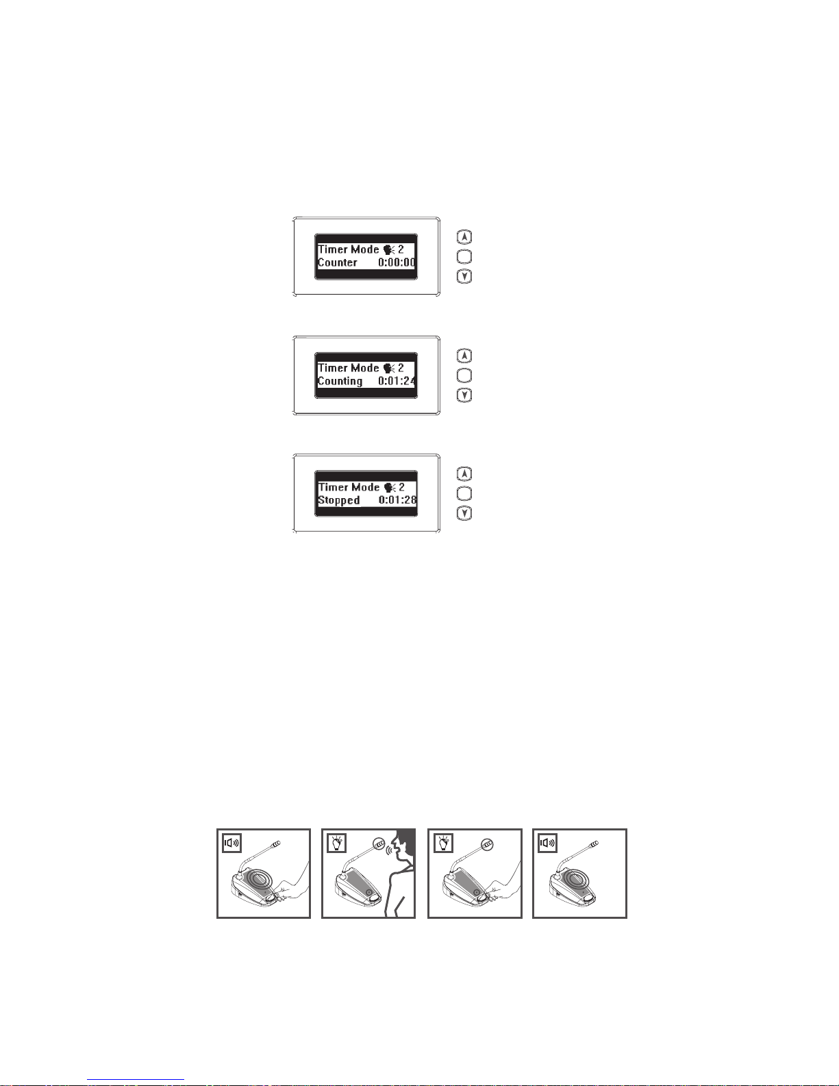
6.4 Counter Operation
1) Press and release the “Set” button; the lower area on the
LCD Display will show “Counter.”
2) Press the “Up” arrow to start counting.
3) Press the “Up” arrow again to stop.
4) Press the “Down” arrow to clear data after stopping.
5) Press the “Set” button again to jump back to the original
display. Notice that you can operate any other functions
of the control unit when the timer is in use.
6.5 Delegate Unit Operation
1) Depending on the microphone mode setting on the CU,
when pressing the microphone “ON/OFF” button, the
gooseneck microphone will be activated.
2) Press “ON/OFF” button again to turn o the
microphone.
SET
SET
SET
1..4 1..4
Page 18
18
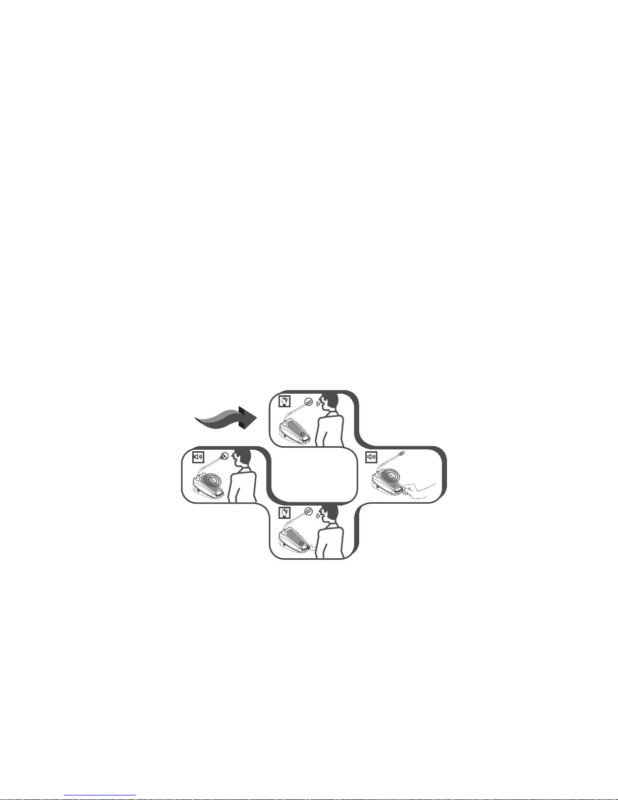
6.6 Chairman Unit Operation
1) Independently of microphone mode setting on the CU,
when pressing the microphone “ON/OFF” button, the
gooseneck microphone on the chairman unit will be
activated.
2) Press the “ON/OFF” button again to turn off the
microphone.
3) If you press and hold the chairman priority button, all
active delegate units will be deactivated and the chairman microphone will be activated. At the same time,
with the default settings, a chime will be heard.
4) With the default settings, when releasing the priority
button, the previously active delegate units will be
reactivated. To modify this, at the bottom of the
chairman unit you will nd a “Constant Priority Switch.”
When switching to “On,” the active delegate units will
not be reactivated after the priority button is released.
There is also a chime switch to turn the chime on/ off.
Delegate
Priority
button
Delegate
Chairman
Chairman
Page 19
19
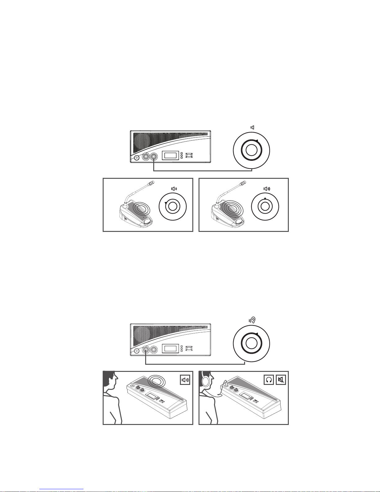
6.8 CU Internal Speaker and Headphone Volume
Control
1) While using the internal speaker or headphone to
monitor the discussion, turn the monitor volume control
to adjust their volume.
2) The maximum volume level is controlled by the speaker
volume control of the CU.
1
2
3
456
7
8
9
100
1
2
3
456
7
8
9
100
1
2
3
456
7
8
9
100
1
2
3
456
7
8
9
100
6.7 Volume Control of the Delegate and
Chairman Units
1) Rotate the speaker volume control to adjust the volume
of the loudspeakers of the delegate and chairman units.
2) In the fully counterclockwise position, all loudspeakers
will be muted.
Page 20
20
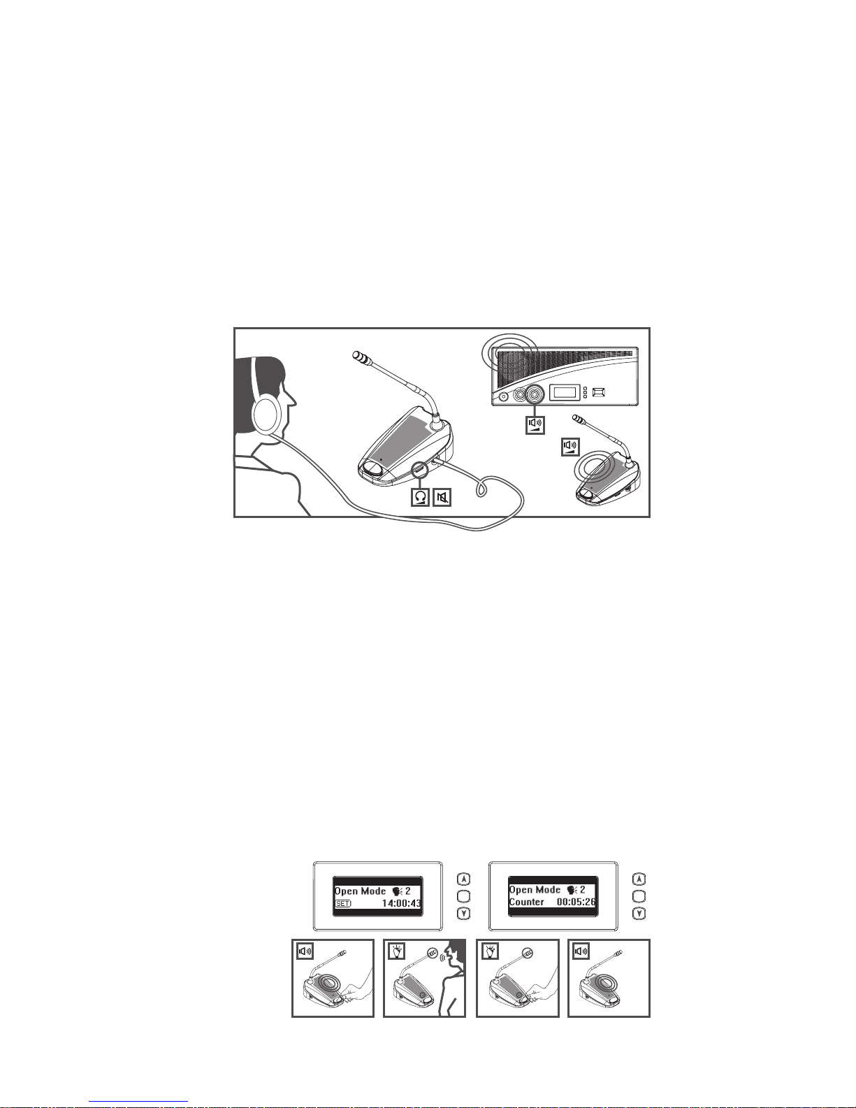
6.10 Open Mode
1) Press and hold the “Set” button for 2 seconds and the
“Set” icon will ash.
2) Press the “Up” or “Down” arrow buttons to choose
“Open Mode” on the Mode Status area of the LCD
display.
3) Press “Set” button again, and the maximum number of
active delegate units (up to 4) will ash.
4) Press “Up” or “Down” arrow buttons to select the
maximum number of active delegate units
(1, 2, 3, 4) you would like the system to allow.
5) Press the “Set” button to save these changes.
Under “Open mode,” press the microphone “ON/OFF”
button on chairman and delegate units to activate the
microphone.
Press “ON/ OFF” again to deactivate it.
1..4 1..4
SET SET
6.9 Using Headphones on Delegate/ Chairman
Microphone Units
1) Connect stereo headphones to the left and/or right side
of the units. This will mute the loudspeaker of the unit
you are connecting.
2) Adjust the volume of the headphones by using the rotary
volume control located on the right side of each unit.
3) The maximum volume level depends on the level of the
speaker volume control on the CU.
Page 21
21
1..4 1..4
SET SET
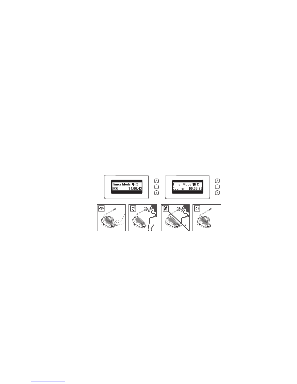
6.11 Time Mode
1) Press and hold the “Set” button for 2 seconds and the
“Set” icon will ash.
2) Press the “Up” or “Down” arrow buttons to choose “Time
Mode” on the Mode Status area of the LCD display.
3) Press “Set” button again, and the maximum number of
active delegate units (up to 4) will ash.
4) Press “Up” or “Down” arrow buttons to select the maximum number of active delegate units (1, 2, 3, 4) you
would like the system to allow.
5) Press the “Set” button to save these changes.
Under “Time mode,” press the microphone “ON/OFF”
button on delegate units, to activate the microphone for
30 seconds. If the number of active delegate units is less
than the maximum allowed, more delegate units can be
activated for 30 seconds.
Page 22
22
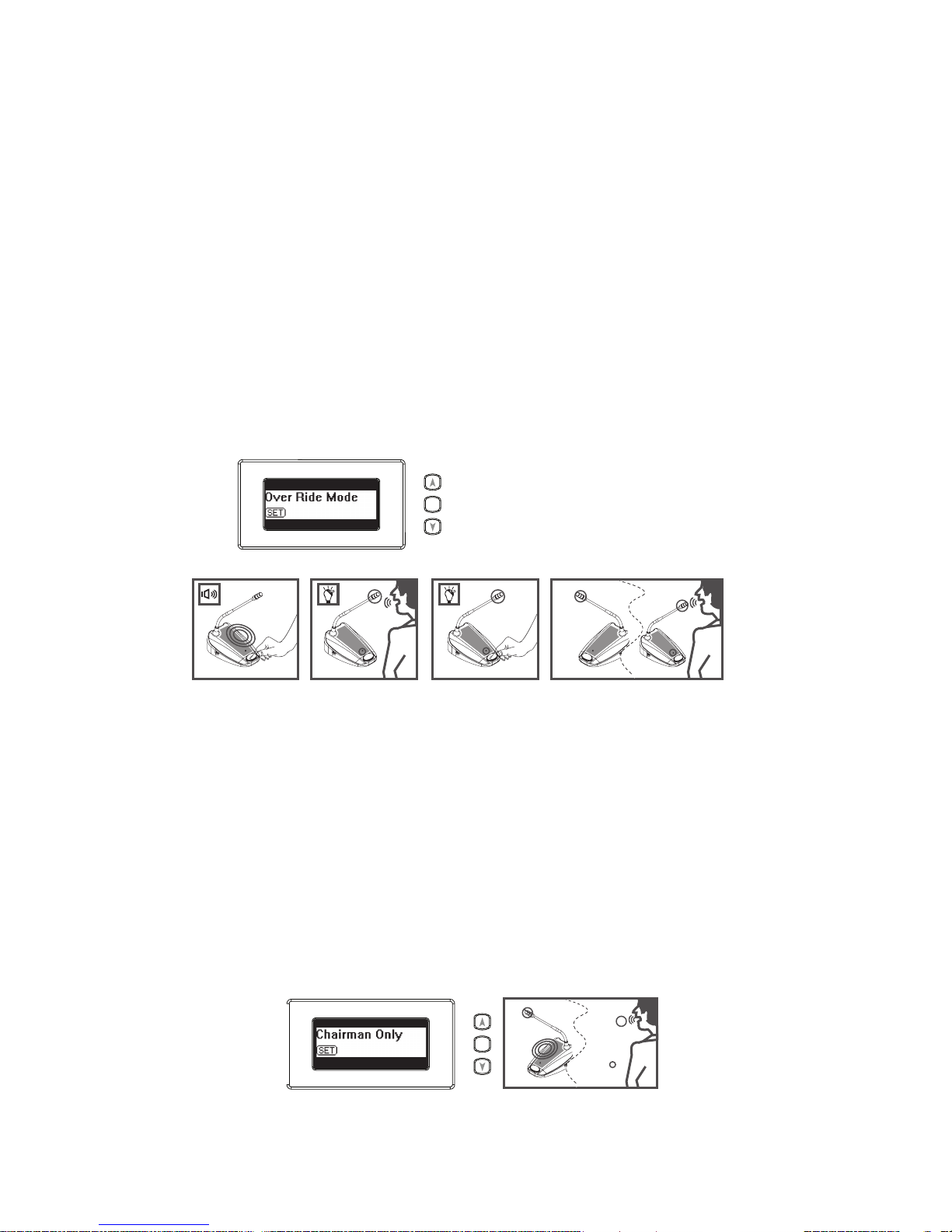
6.12 Override Mode
1) Press and hold the “Set” button for 2 seconds and the
“Set” icon will ash.
2) Press the “Up” or “Down” arrow buttons to choose
“Override Mode” on the Mode Status area of the LCD
display.
3) Press the “Set” button to save these changes.
Under “Override mode,” the system will only allow one
delegate unit to be activated. Press the microphone “ON/
OFF” button on one delegate unit to deactivate the
previously active delegate unit and to activate the new
one.
6.13 Chairman Only Mode
1) Press and hold the “Set” button for 2 seconds and the
“Set” icon will ash.
2) Press the “Up” or “Down” arrow buttons to choose
“Chairman Only Mode” on the Mode Status area of the
LCD display.
3) Press the “Set” button to save these changes.
Under “Chairman only mode,” the system only allows
chairman units to be activated. All delegate units will be
deactivated.
AA BA B
SET
A B
SET
Page 23

23
7. Technical Data
7.1 Electrical and Electro-acoustical Characteristics
7.1.1 Control Unit CU-300
Operating voltage: 100-240 VAC, 50/60 Hz (auto-switching)
Current consumption: MAX 0.9A (100VAC) 0.3A
(240VAC) DC supply to contribution units: ±15V
Line, Telephone Coupler and Insertion In/Outputs (Unba-lanced)
• Input sensitivity: -14dBV/+11dBV (nominal/maximum)
• Input impedance: 33KΩ
• Output level: -14dBV/+11dBV (nominal/maximum)
• Output impedance: 500Ω
Recorder In/Out (Unbalanced)
• Input sensitivity: -20dBV/+5dBV (nominal/maximum)
• Input impedance: 47KΩ (for L & R channel)
• Adjustment: -20dBV/+5dBV
• Output level: +0/-30dB
• Output impedance: 500Ω
External Microphone Input (Balanced)
• Input sensitivity: -56dBV
• Adjustment: +6dB/-6dB
• Phantom Power: 12V+/-1V, 2 x 680Ω (+/-2%)
• Output connection: 3.5mm stereo jack
Headphone Output
• Output level: -8dBV/+2dBV
• Output Impedance: 22Ω
System Limits
Number of delegate/chairman units connected to CU
• Maximum total: 50
• Maximum per trunk output: 25
• Maximum trunk length using CU-300: standard cabling:
100m (328’) including the 2 m cables attached to each unit
7.1.2 Chairman Unit CH-300 & Delegate Unit DU-300
Gooseneck Microphone:
• Type: Electret Condenser
• Frequency response: 50 to 18,000Hz
• Polar pattern: Cardioid
• Max. SPL for 1% THD: 125dB
• Gooseneck length: 15” / 40 cm
Page 24

24
7.2 Mechanical Specications
7.2.1 CU-300
Dimensions (HxWxD): 360 X 150 X 90 mm
Weight: 2 lbs 11 oz / 1215 g
7.2.2 CH-300 & DU-300
Dimensions (HxWxD) without mic.: 170 X 115 X 65 mm
Length of mic.: 15.75’’ / 40 cm
Weight: 2 lbs 7 oz / 1100g
7.3 General Specications
Environmental conditions
Temperature range
Storage and transport: -4 to 131°F / -20 to 55°C
Operating temperature: 41 to 113°F / 5 to 45°C
Ambient humidity
Storage and transport: 0% - 99% RH
Operational: 20% -95% RH
FCC statement:
This device complies with Part 15 of the FCC Rules.
Operation is subject to the following two conditions:
(1) this device may not cause harmful interference,
and (2) this device must accept any interference
received, including interference that may cause
undesired operation.
Page 25
25
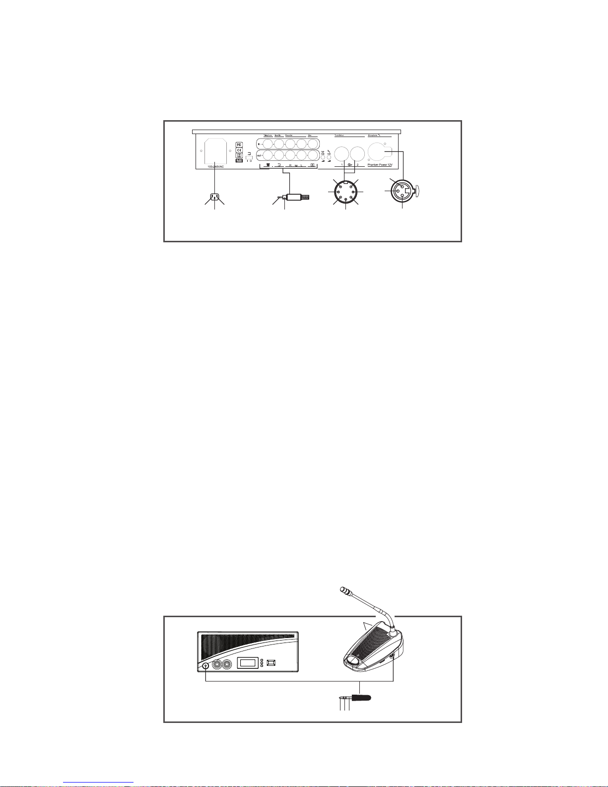
7.4 Pin Conguration
Trunk Connections
1) Audio contribution line
2) Ground (GND)
3) Audio distribution line
4) Control line 1
5) Control line 2
6) V+ supply
7) V- supply
External Microphone (XLR)
1) GND (0V, phantom power)
2) Signal + (+12V, phantom power)
3) Signal – (+12V, phantom power)
RCA Connector
1) Signal +
2) Signal Power Connector
1) Mains
2) Ground
3) Mains
Headphone Jack-Plug (3.5mm)
1) Tip (Signal +)
2) Ring (Signal -)
3) Sleeve (Electrical Ground/Screen)
6
1
4
2
5
3
7
3
2
1 1
2
1
3
2
Power
Connector
Trunk
Connections
External
Microphone (XLR)
3
21
Headphone Jack-Plug (3.5mm)
RCA
Connector
Page 26

26
8. Limited Warranty Statement
Enersound warrants its CS-300 Conference and
Discussion System: CU-300, CH-300 and DU-300 to be free
from defects in workmanship and material under normal use
and conditions for one year from the date of purchase from
an authorized dealer. All other products and accessories are
warranted for 90 days from date of purchase. This warranty
is only available to the original end purchaser of the product
and cannot be transferred. If the product is determined
to be defective, Enersound will repair or replace it, at its
discretion, at no charge. Customer must pay for shipping.
This warranty is void if damage occurred because of misuse
or if the product has been repaired or modied by anyone
other than a factory-authorized service technician. Warranty
does not cover normal wear and tear on the product or any
other physical damage unless the damage was the result of a
manufacturing defect.
Enersound has no control over the conditions under which
this product is used. Therefore, the company disclaims all
warranties not set forth above, both express and implied,
with respect to the CS-300 Conference and Discussion
System, including but not limited to any implied warrantyof merchantability or tness for a particular purpose.
Enersound CS-300 Conference and Discussion System’s
manufacturer, distributors and/or dealers shall not be liable
to any person or entity for any medical expenses or any
direct, incidental or consequential damages caused by any
use, defect, failure or malfunction of the product, whether
a claim for such damages is based upon warranty, contract,
tort or otherwise. The sole remedy for any defect, failure or
malfunction of the product is replacement of the product.
No person has any authority to bind Enersound to any
representation or warranty with respect to the CS-300
Conference and Discussion System. This warranty gives
you specic legal rights, and you may also have other rights
which vary from state to state. Some states do not allow
limitations on how long an implied warranty lasts, and the
exclusion or limitation of incidental or consequential
damages, so the above limitation may not apply to you. This
warranty applies to products sold only within the United
States of America and does not cover products sold AS IS
or WITH ALL FAULTS. For products sold outside the U.S.,
please consult with your local dealer about the terms and
conditions applicable in your country. Proof of purchase in
the form of a bill of sale, invoice number or receipted
Page 27

27
invoice, which is evidence that the unit is within the
warranty period, must be presented to obtain warranty
service. If you experience difculty with your
CS-300 Conference and Discussion System, send an email
to [email protected] with your name, address, phone
number and a complete description of the problem. We will
respond to you as soon as possible and if it is necessary to
return the product for service, your Customer Service
Representative will give you a Return Authorization
Number (RAN) and shipping instructions. For more
information, visit www.enersound.com. You may also call
1-305-731-2416 or our toll-free number 1-800-644-5090
within the U.S.
Page 28

 Loading...