

Page 1
1.800.884.6444
www.enersol.com
April, 2013
© 2013 Enerworks
Page 2

Enersol Pool Panel Installation Guide
2 | P a g e
Page 3
Enersol Pool Panel Installation Guide
PANEL BOX
4 sections with pre attached headers
8 clips
10 lag bolts
8 O-rings
3 long straps (48”)
4 short straps (12”)
TOOLS REQUIRED
Ladder, Safety gear (safety glasses, fall arrest, and
boots), Variable speed drill, 5/16” and 3/8” socket
drivers, Level, Hacksaw, Chalk line, Utility knife,
Caulking gun, Various tools (pliers, etc.)
SYSTEM KIT (Purchased separately – 1 per install)
1 warranty card
1 installation guide/owner’s manual
1 Enersol installation DVD
1 orange installation tool
1 tube lag bolt roof sealant
1 tube O ring lubricant
2 end caps
2 O rings
ADDITIONAL PARTS REQUIRED
PVC heavy bodied cement
1 ½” - 2” elbows
1 ½” - 2” tees
1 ½” – 2” pipe
pipe hold downs (1 ½” and/or 2”)
1 ½” – 2” couplers
Extra lag bolts
3-way manual valve or
Automatic controller with 3-way valve
One way check valve
1 ½” – 2” ball valve
Teflon tape
SOLAR PANEL INSTALLATION
INFORMATION
If for any reason whatsoever, the installer of this
product does not feel comfortable and/or safe do
not proceed with the installation. The installation of
this product involves walking on the roof as well as
climbing ladders. Do not attempt unless you
understand all safety procedures involved with
power tools, climbing ladders and working on roofs.
To obtain ladder safety, roof safety and power tool
safety procedures, contact your local Hardware or
Building Supply Company and State or Provincial
Worker’s Safety Board.
The installation of Enersol Solar Panels may be
performed on a low pitched (less than 12:12 or 45
degrees angle) shingle and some types of metal
roofs. If an installation varies from these types,
Enersol should be advised and asked for special
installation instructions, visit our website or contact
your roof manufacturer. For example, on a flat roof
installation, we do not advise cutting into the roof or
drilling lag bolts into the roof.
EnerWorks Inc., its agents, distributors
and sales representatives of the Enersol
solar products are in no way responsible if
safety procedures, installation instructions and
common sense are not followed, or if EnerWorks
is not consulted should an unusual problem
arise. EnerWorks assumes no liability for
installation, parts or labor. If for any reason, you
question the installation instructions, DVD,
safety procedures and/or installation locations,
do not proceed, and contact EnerWorks
immediately at: 1-800-884-6444.
Remember… SAFETY FIRST!
3 | P a g e
Page 4
Enersol Pool Panel Installation Guide
Panel Size
Number of Boxes / Array
4’ x 8’
7 - 9
4’ x 10’
6 - 8
4’ x 12’
5 - 7
Custom size
Consult with EnerWorks
ASSEMBLY INSTRUCTIONS
OVERVIEW
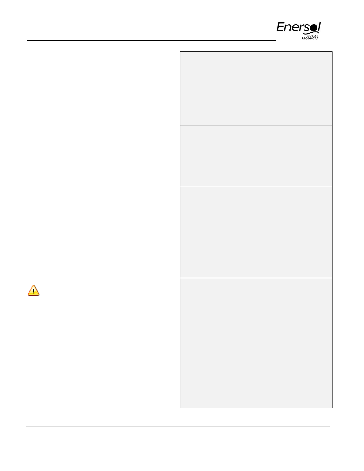
1 - Plan your system:
a) Determine the location; south is best
followed by west or east. North is not
recommended. Panels should be tilted at an
angle of 45° or less.
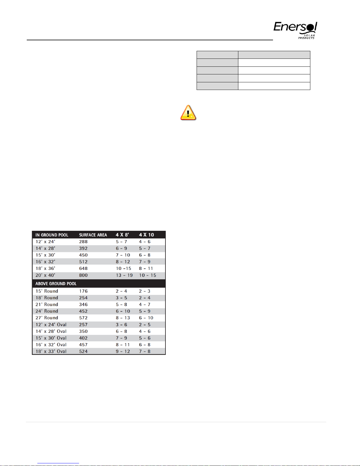
b) Determine the optimum number of boxes
needed. The following quick sizing guide will
help you establish the number of boxes of
solar panels required for your pool. The
lower number is for a south facing roof with
full sun. If the roof is west facing or has more
shade, you will need the larger number. The
solar rule of thumb is 50% of the pool
surface should be represented in solar panel
area. Indoor pools require 100% coverage.
If panel area exceed number of boxes that can be
installed in one array (see table) panels must be split
to equally sized arrays. See typical split-array
reverse return.
For additional information in sizing the
system please see System Design
considerations or call EnerWorks for
assistance at: 1-800-884-6444.
c) Measure roof area available to be sure the
panels will fit: Panels must be positioned
vertically from eave to peak with at least 6”
space around the panels for plumbing and
workspace. Four sections of connected
headers measure 51” and rubber panel strip
width measures 48”.
d) There are several different types of roofs.
Most will accommodate the entire panel
system in a continuous row. However, some
systems may need to be split over two or
more arrays or two or more roofs. When
splitting a system, you must balance equal
sections in each array. Remember to be
conscious of the best sun exposures, and
avoid roofs with shade. If your system is
divided between two different exposures
(east and west) then plumb from the cold
side (east) to the warm side (west).
e) Check that your existing pool pump is in
good working order. Verify that pool pump is
sized accordingly and that it will not exceed
the maximum panel flow. For information on
pump size see System Design
Considerations or consult with EnerWorks
at 1-800-884-6444.
f) Plan for the plumbing and fittings required.
Ensure no to exceed maximum velocities
allowed on pipes when selecting pipes
diameters as per table below. See System
Design Considerations for more
4 | P a g e
Page 5
Enersol Pool Panel Installation Guide
Pipe Size
Velocity
6 fps
8 fps
10 fps
1-1/2"
35 gpm
50 gpm
62 gpm
2"
62 gpm
85 gpm
105 gpm
2-1/2"
90 gpm
120 gpm
150 gpm
3"
140 gpm
187 gpm
230 gpm
ASSEMBLY INSTRUCTIONS
(CONTINUED)
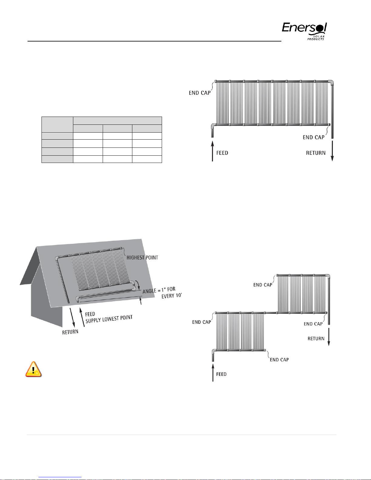
TYPICAL PARALLEL ROOF
information on how to size the line set or
consult with us at: 1-800-884-6444.
g) Gather all components and tools required for
the job.
TYPICAL PITCHED ROOF MOUNT
TYPICAL SERIES ROOF
When installing solar panels bank in series as
diagrams below, care must be taken not to exceed
panel maximum pressure capacity, and arrays must
be of same size in order to minimize restrictions.
Please refer to System Design Considerations for
further explanation.
Important: Angle panel headers inch for e
very 10 feet to drain water back to
feed/supply inlet. Use chalk lines to
reference angle.
5 | P a g e
Page 6
Enersol Pool Panel Installation Guide
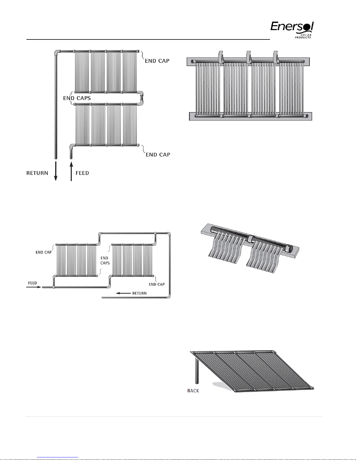
TYPICAL GROUND MOUNT
Support headers with 2x6” lumber. Panels may be
set on any material that will insulate them from the
earth: plywood, metal, plastic or gravel. Note: Flat
TYPICAL SPLIT-ARRAY REVERSE
roof or ground mount panels will not gain heat if
sitting in puddles of water, always ensure proper
drainage.
RETURN
TYPICAL FLAT ROOF MOUNT
Attach headers to 2x6” lumber on each end. 2x6”
lumber may then be attached to roof using liquid
adhesive. Ensure that the rubber is not blocking any
roof drainage.
TYPICAL RACK MOUNT
For safety reasons do not mount panels against a p
ool. Rack plywood should be mounted 45° or less.
6 | P a g e
Page 7
Enersol Pool Panel Installation Guide
ASSEMBLY INSTRUCTIONS
(CONTINUED)
2 - Roll out panels on roof, rack or
ground:
b) Continue this procedure for the top headers
a) Carry the boxes to the installation area.
b) If installing on a roof – snap a chalk line as a
guide to where the top of the panels will be
aligned. It is important to place the panels on
a slight angle on the roof. This helps purge
the air from the system when filling, and
provides drainage when draining for the
winter. Angle the panel headers 4” for every
40 feet with the slope down toward the end
that has the feed line
(lithium based)
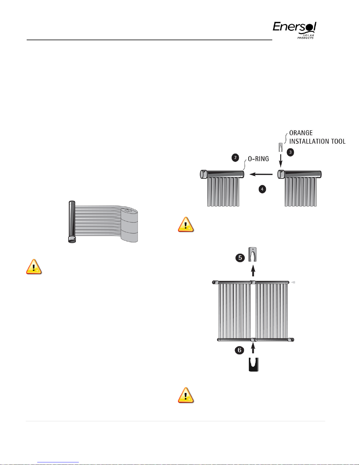
3 clip the orange installation tool into the slot
on the next header
4 push the two sections together
5 remove the installation tool
6 insert black clip to complete the connection
until all the panels are connected.
The orange installation tool must be
used to prevent damage to the O-rings
Remove from box carefully and unroll
panels. If panels become tangled, lay
flat and untwist strips from one end to
the other
c) Carefully take the sections out of the box
(give each roll a twist to tighten and pick up
from the bottom to prevent tangling), set
down, evenly arrange, and allow each
section to unroll.
3 - Clip together using the installation
tool included with the required
System Kit.
a) Keep the top header close to the reference
chalk line as you begin the assembly.
1 put an O-ring on the first header
2 lubricate the O-ring, with supplied lubricant
When connecting different versions of
headers, always cut off locator tab
before connecting.
7 | P a g e
Page 8
Enersol Pool Panel Installation Guide
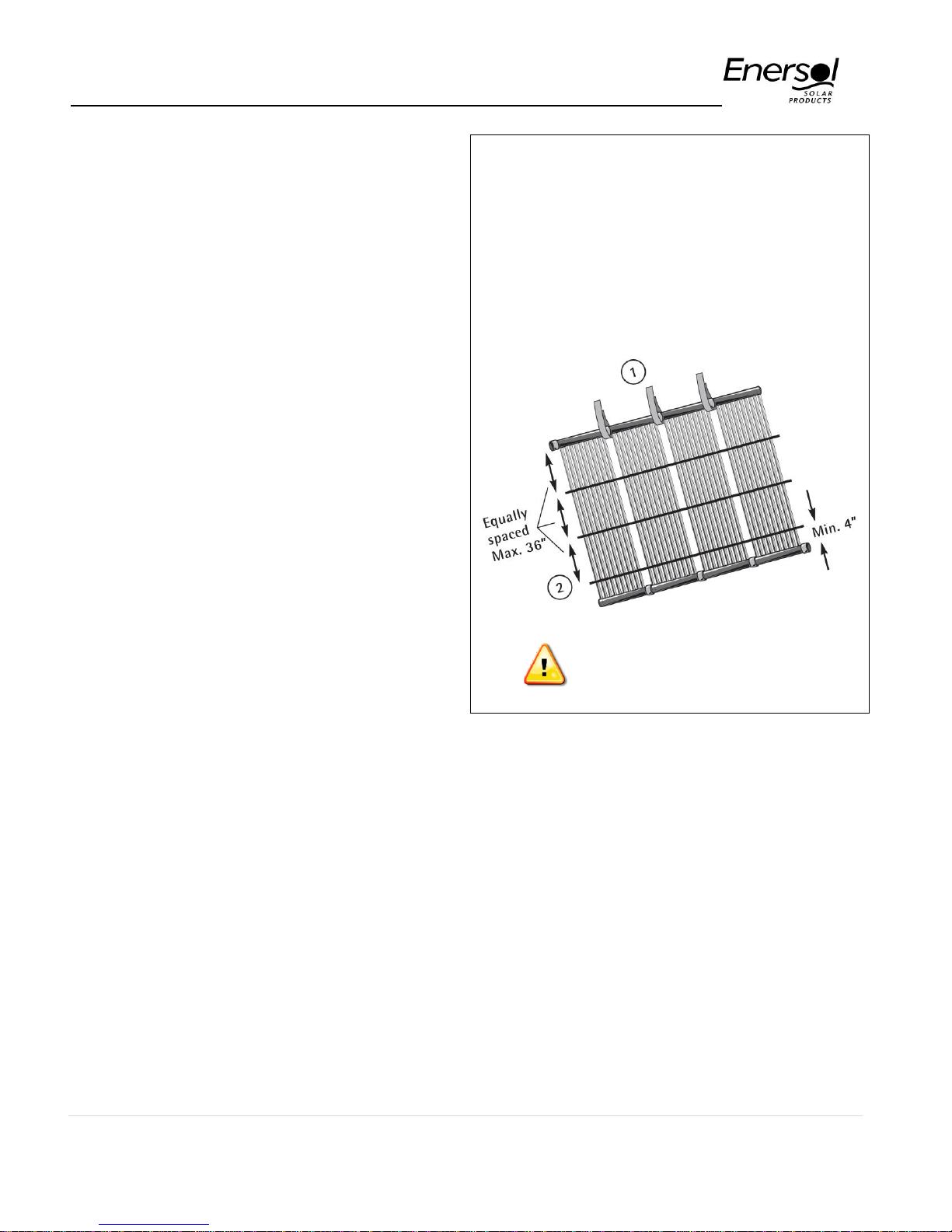
4 - Strap down headers and panels
a) Starting at the top end, secure the headers
to the roof by placing header straps (12”
long) on every clip connection.
b) Loop the strap around the top header, bring
the two grommets together and push the
threaded lag bolt through the grommets.
Check for proper tension, apply a generous
dab of roof sealant on the chalk line and
secure the lag bolt to the roof. Repeat this
for every header until complete the top row
strap installation.
c) On steeper roofs, you may want to strap the
headers one at the time while you are
making the connections to prevent the entire
assembly from slipping down.
d) Always straighten the bottom headers by
pulling gently and join together as the top
headers (see step 3), Bottom headers are
not strapped down.
e) To complete the securing process, cross
strapping (48” long) is used. The straps are
attached grommet to grommet across the
entire width of panels. Starting from the top,
the cross straps should be equally spaced at
no more than 36 inches apart. Fasten using
the proper lag bolts and roof sealant
provided. The last row, nearest to the bottom
should be no more than four inches from the
bottom header. Bottom headers are not
strapped down to allow for expansion and
contraction of the panels. When installing
longer custom sizes panel they may require
additional horizontal strapping.
f) If your roof has a membrane, or cannot be
punctured, it is possible to attach a lumber
frame to the roof with liquid nails adhesive
and attach the lag bolts into the lumber.
(Contact your roof manufacturer for advice).
Attach to Roof
1 Top strap: Install a strap every section across top
only.
2 Cross Strap: Install Cross strapping equally
spaced along the length of the collector, making
sure to leave at least 4 inches from bottom. Do not
over tighten cross strapping, to allow for expansion.
Apply a generous amount of roofing cement. Screw
lag bolts through roofing cement into roof. Use roof
sealant liberally with all lag bolts into roof.
Never use top straps on bottom
headers
PLUMBING
5 - Connect Plumbing
Join Plumbing to Headers
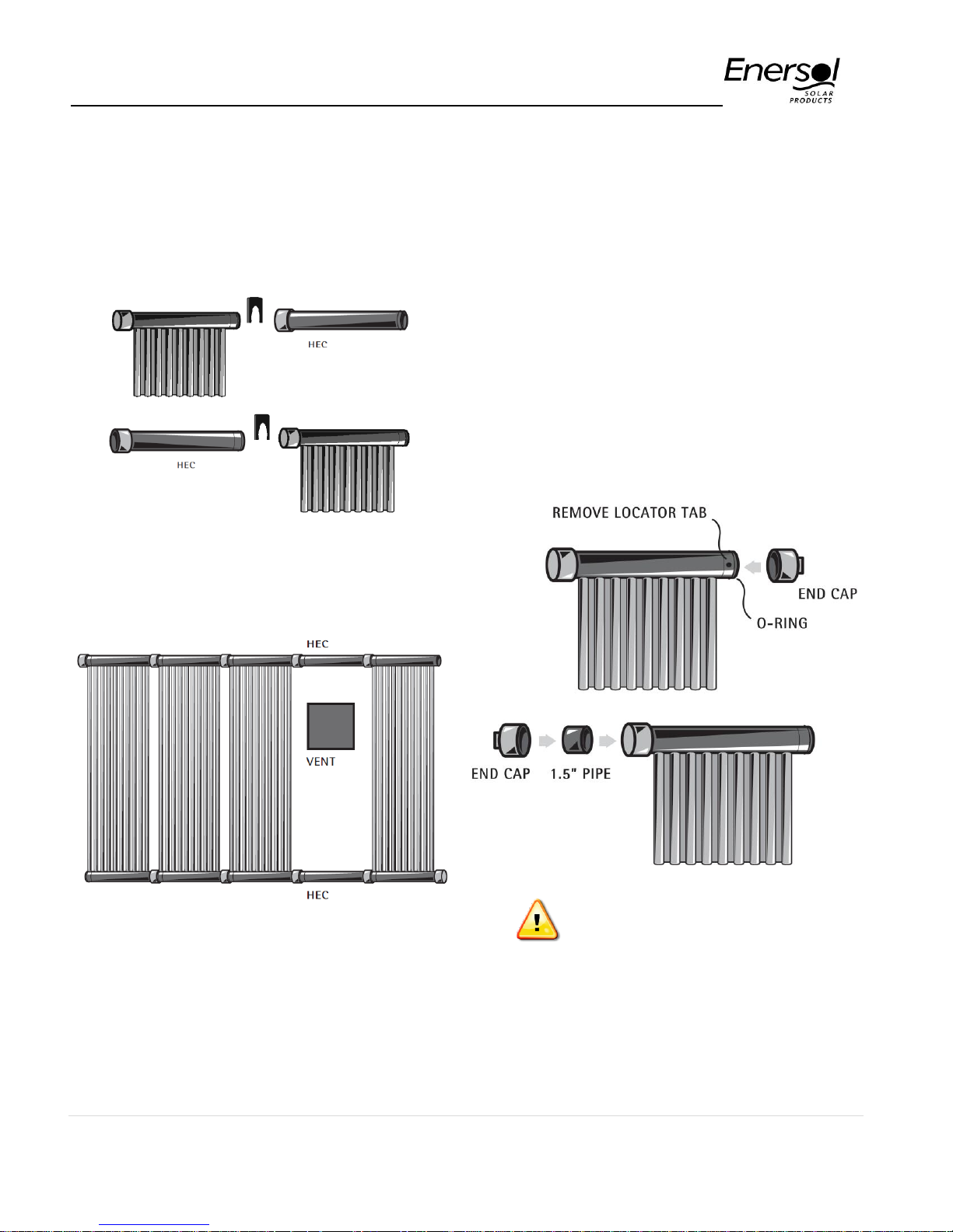
a) The Header End connector (HEC) included
in your system kit creates a male and a
female adapter.
Clip the header end connectors (HECs) to
the headers, diagonally opposite of one
another, at the input and output of the array
so that the plumbing can be glued to the
HEC instead of the header.
8 | P a g e
Page 9
Enersol Pool Panel Installation Guide
5 - Connect Plumbing (continued)
Remember the feed line goes in the bottom
and return comes out the top on the opposite
side.
HECs can also be used as spacers around small
roof vents or similar obstacles. (Purchased
separately – see drawing below)
FOR MALE END:
• Remove O-ring
• Cut locator tab off
• Apply transitional solvent cement liberally to
both male and female surfaces
• Cement together
FOR FEMALE END:
• Cut a piece of 1.5” pipe to 3” long
• Apply PVC cement liberally to all surfaces
and glue together
Always use Teflon tape on the removable threaded
plug of the end cap to prevent leaking (removable
threaded plug can be removed to allow for
drainage).
Join end-caps to Headers
b) Connect the end caps to the remaining
headers. To do this liberally apply cement to
the inside lip end of the end cap, steering
clear of the threading.
Use Teflon tape on all End Caps
c) Complete the roof installation by connecting
the supply and return water lines: measure
twice cut once! If you are travelling a
substantial distance from the panels to the
pool, consider insulating the underground
pipes.
9 | P a g e
Page 10
Enersol Pool Panel Installation Guide
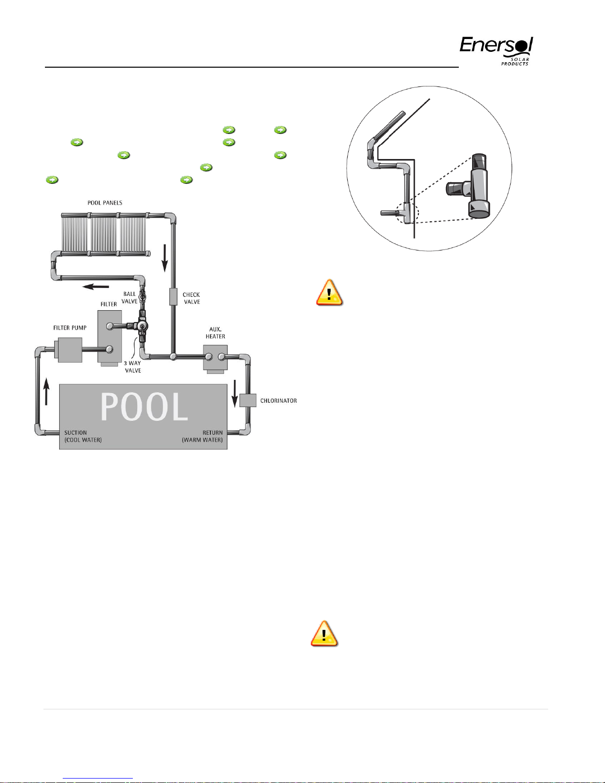
d) Plumbing Layout:
Cool feed from pool (water sensor) pump
filter manual or automatic valve ball valve
(flow regulator) solar panels (panel sensor)
return from panels (check valve) auxiliary heater
salt generator/chlorinator return to pool
At any low points in plumbing, use a
tee and end cap to allow for drainage
during winter months
SYSTEM REGULATION OPTIONS
e) The recommended 1.5” or 2” PVC pipes are
attached to the roof and side of the house
with plastic clamps and secured with lag
bolts and roof sealant
f) Be sure to measure and dry fit all pieces to
ensure a proper and neat fit around all eaves
troughs, then cement (using grey heavybodied PVC cement) the connections and
assemble. The pipes should be secure,
straight, even and close to the house.
g) At any low point in the plumbing use a tee
and end cap. This will allow for drainage.
6 - A valve is necessary to divert
the water to the panels.
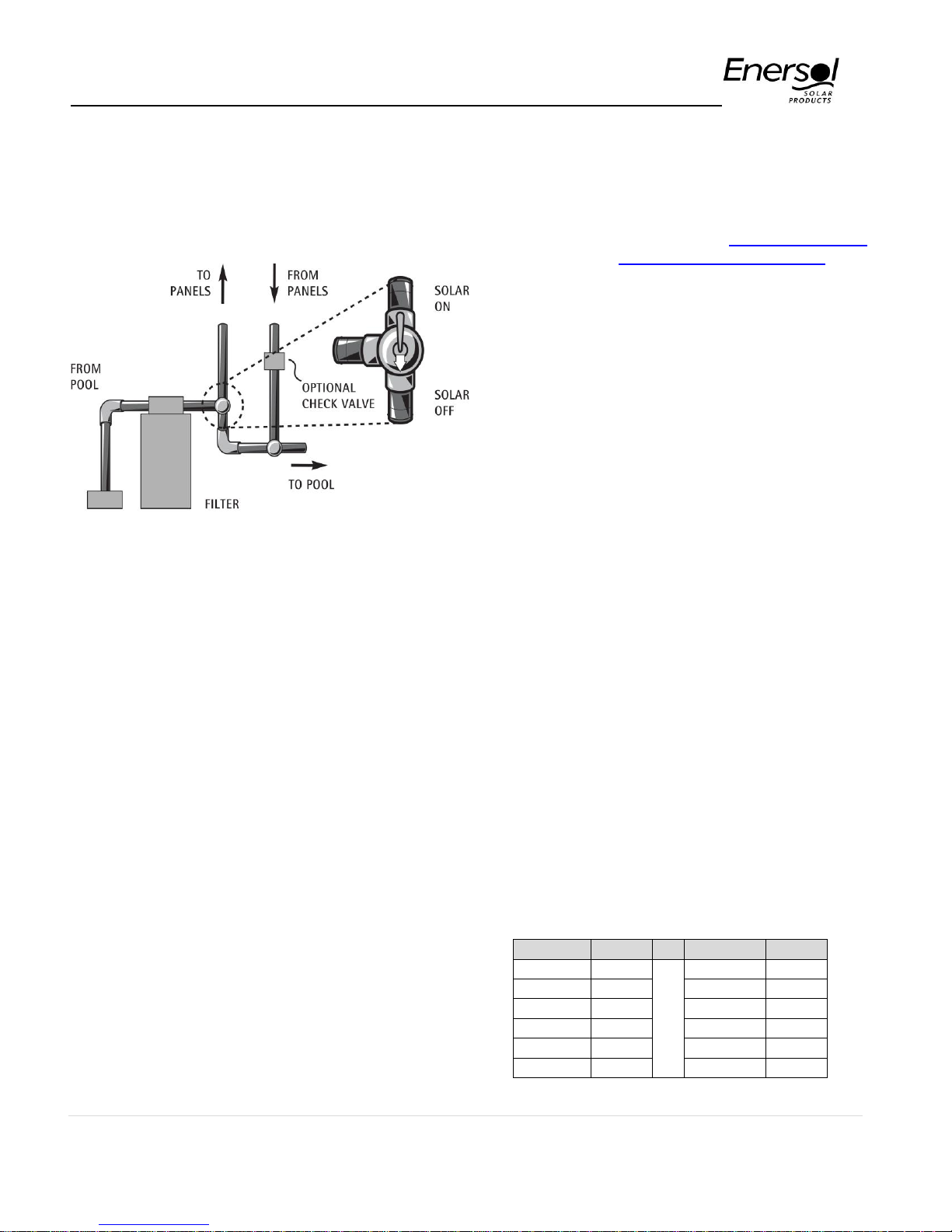
a) A 3-PORT MANUAL VALVE can be used; it
must be turned on and off manually when
the temperature fluctuates during the day to
get the most out of the sun, and must be
turned off at night. The valve is installed in
the feed line from the pool, with the water
coming into the inlet opening. The handle
can then be turned to divert the water to the
panels on sunny days or directly to the pool,
when not using the panels. Remember that
the water flows in the direction that the free
part of the handle is pointing, and the
Indicator points to the closed side.
If manual valve is left “ON” for long
periods of cold weather or at night
pool will lose heat
10 | P a g e
Page 11
Enersol Pool Panel Installation Guide
Temp °F
Kohms
Temp °F
Kohms
65
13.5 95
6.5
70
11.9 100
5.8
75
10.5 105
5.2
80
9.3 110
4.7
85
8.2 115
4.2
90
7.3 120
3.8
6 - SYSTEM REGULATION
OPTIONS (continued)
3-WAY MANUAL VALVE
b) A CHECK VALVE is optional, but
suggested, to be installed on the return line.
This will prevent back flow to the panels, and
is also required for the Summerization of
the system. In some cases a check valve
can prevent losses from heat thermo
siphoning out of the pool.
• Flick the switch to SOLAR TEST. Synchronize the
valve handle by flipping the toggle switch at the
bottom of the actuator between ON 1 and ON 2 to
rotate the handle so it points to the solar panel
feed line. See full instructions for valve actuator in
package, or visit our web site, www.enersol.com
and look under “System Automatic Controller”.
d) WATER SENSOR
Install the plastic cylinder shaped sensor by
drilling a 5/16” hole into the pipe usually
between the filter and diverter valve. The
gear clamp holds the sensor in place. Two
wired connectors are supplied to connect the
sensor to two line sensor wire. The other end
is wired into the control box (pool sensor
screws).
e) PANEL SENSOR
Install the sensor on the roof or rack where it
receives sunlight similar to the solar panels.
Two wire connectors are supplied to connect
the sensor to two wire sensor cable. The
other end is wired into the Control Box (solar
sensor screws). The plastic wire protector fits
in the hole located in the bottom of the control
box.
c) An AUTOMATIC VALVE relies on water and
panel temperature sensors to divert the
water. EnerWorks suggests the Aqua Solar
controller kit. The kit comes with a 3-port
diverter valve, actuator, control box and two
sensors. Follow manufacturer’s instructions
for installation of automatic control box,
motorized valve (actuator) and controls.
• Install the Control Box as outlined in
manufacturer’s instructions. Be sure to wire
correctly.
• The 3-port valve (diverter) is installed as above.
• Remove the locking knob and handle.
• Remove 4 screws from the valve (fit actuator on
valve to determine which screws to remove).
• Align the actuator; rotate the actuator until holes
on the actuator align with the screw holes.
• Use the 4 supplied screws to secure in place.
• Plug the actuator in the Control Box in the FWD
VALVE socket.
f) VACUUM BREAKER
A vacuum breaker is not necessary, as the
Enersol Panels do not collapse when drained.
g) OHM-METER
Use an Ohm meter to check the resistance in
the sensors. The Ohms readings should
correspond with the sensor temperature. Use
the chart below to determine if the sensor is
sensing proper temperatures.
11 | P a g e
Page 12

Enersol Pool Panel Installation Guide
Finally: double check all your joints, plumbing and
wiring. Pressure test the system to test for leaks,
then let the cement set for 3 hours. Turn your filter
pump back on to get the water flowing.
• Manual Valve: Turn handle to divert water to the
panels.
• Automatic Valve: Flick the switch to Auto.
Congratulations! Enjoy your warm pool for many
years.
Best Regards,
Team EnerWorks
12 | P a g e
Page 13
Enersol Pool Panel Installation Guide
Pipe Size
Velocity
6 fps
8 fps
10 fps
1-1/2"
35 gpm
50 gpm
62 gpm
2"
62 gpm
85 gpm
105 gpm
2-1/2"
90 gpm
120 gpm
150 gpm
3"
140 gpm
187 gpm
230 gpm
Losses (PSI) per 100 ft
GPM
1.5" DIA
2" DIA
30
3.16
0.79
60
10.97
2.75
90
22.88
5.7
Panel Size
Number of Boxes / Array
4’ x 8’
7 - 9
4’ x 10’
6 - 8
4’ x 12’
5 - 7
Custom size
Consult with EnerWorks
SYSTEM DESIGN
CONSIDERATIONS
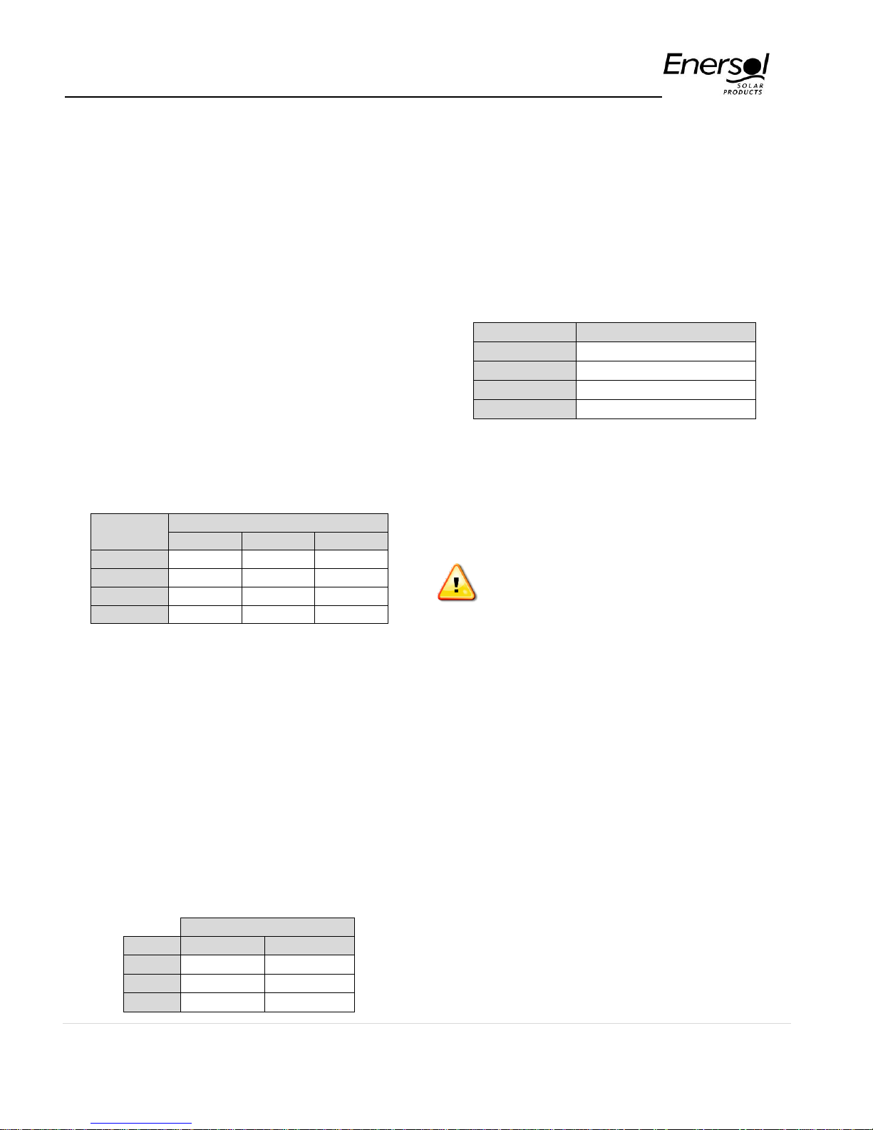
a) Line Set: in this guide “line set” refers to
the piping system carrying the water to and
from the solar panels. Typically
recommended values for water velocity on
pipe are between 6 and 8 feet per second
(fps) on the suction lines and 8 to 10 fps on
the return lines. In order to properly size
line set diameters you need to know the
flow rate of the system to ensure not
exceeding max velocity. Always check with
local regulations to ensure compliance.
Failure to properly size line set diameters
will cause early deterioration of the piping.
The table below shows the water flows in
different pipe sizes with the corresponding
velocities.
Line set length also has a negative effect on
losses; the longer the pipe the higher the
losses. A very large line set (more than 100
feet) will create additional losses to the solar
system, which can be translated into higher
operating pressures. When using large runs
of pipe is recommended to increase the pipe
diameter to minimize the losses. If losses
exceed the operating pressure for the panels
it may create leaks.
Table below illustrates the pressure loss on PSI for
every 100 feet of pipes of different diameters.
b) Panel Array Size: every component on a
hydraulic system creates resistance or
friction losses, pool solar panels do not
escape this reality; care must be taken when
determining the size of the pool panel array
(especially on large pool systems) not to
exceed the panel capacity. Use the table
below as a guideline when determining the
panel array sizes.
When the pool is too large and requires
more panels than the number recommended
on table above, the array must be split into
two or more parallel arrays of equal size
interconnected using reverse return
techniques.
Failure to properly size solar panel
array may result in panel over
pressurization and/or failure
For detailed information on pressure losses for
the Enersol solar panels please see Appendix 1.
a) Flow rate: flow rate is usually measured in
gallons per minute (GPM) and is determined
by analyzing the pump size, total losses from
the hydraulic system, and turnover rate
required. Adequate flow rate will ensure
proper sanitation, even heat and chemical
distribution in the pool. When installing a
pool collector system on an existing pool,
care must be taken not to interfere with the
original system characteristics. Always follow
the recommendations in this guide to avoid
issues.
When retro-fitting an already designed pool with
solar panels with an oversized pump, a ball valve
can be installed between the 3-port valve that diverts
the flow to the solar panels and the panels and be
used as regulator valve to ensure proper flow
through the solar panels.
13 | P a g e
Page 14
Enersol Pool Panel Installation Guide
Friction Loss for Pipe Fitting
90° elbow
7.4 to 11 feet added
45° elbow
2.1 to 4 feet added
Gate valve
1.2 to 1.9 feet added
Check valve
15 to 27 feet added
Coupling
.5 feet added
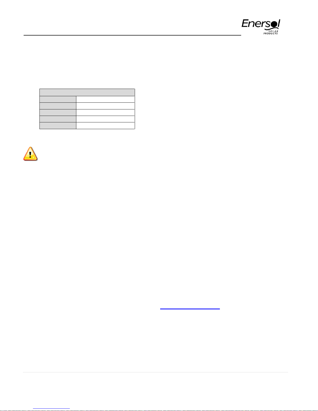
Pipe fittings also add losses to the system,
excessive amount of fittings will increase the
pressure on the hydraulic system affecting the
flow rate. See table below for an equivalent
length of straight pipe in Feet of losses added to
the system for various fittings.
If assistance is required during the
stage of a pool system please contact
EnerWorks for technical support at:
1.800.884.6444
Turnover rate requirements are established by
regulations in order to maintain proper sanitation
levels on the pool water. Always check local
regulations for TOR when designing a pool system.
Below are typical TOR used on pool design:
– Public pools: water circulation = 4+ per 24 hrs
/ TOR of 6 hrs
– Commercial pools: water circulation = 2+ per
24 hrs / TOR 12 hrs
– Hot Tubs: water circulation = 48+ per 24 hrs /
TOR 30 min
– Residential pools: water circulation = 1 per 24
hrs
• The Enersol System is not potable water
compatible. Is not recommended for use with
glycol, and cannot be used in a pressurized
water system.
• The Enersol Pool panel is not designed for
winter use.
• The recommended operating pressure for the
solar panel is 15 PSI @ 120°F, with a maximum
fluid pressure of 17 PSI @ 120°F
• Recommended flow rate for the solar panels is
0.166 gallons per minute for every square feet
of solar panel (0.166 GPM / Ft2)
ADDITIONAL TECHNICAL INFORMATION
• Use PVC pipe for plumbing, ABS is not UV
stable and will degrade with outdoor use
• The Enersol solar panels are designed to be
installed at a tilt angle of 45 degrees or less with
the flow (rubber sections) running vertically from
bottom to top header
• Do not install Enersol solar panel on a fence or
wall at 90 degrees
• Avoid installing solar panels below the level of
the pool, otherwise there will be pressure issues
• Use Weld-On 711 PVC cement or heavy bodied
PVC cement.
• Ensure plumbing is straight. Measure twice cut
once!
• One System Kit is needed for each installation. If
you are installing multiple arrays, you will need
extra end caps.
• At any low points in plumbing, use a Tee and
end cap. This will allow for drainage in the winter
months.
• Covering the panels with glazing (Plexiglas or
glass) is not recommended.
• A vacuum breaker valve is not required on the
Enersol System
• Always install solar panels of at least 50% of the
pool area, and never less than one box.
SOLAR PANEL STRAPING
REQUIREMENTS FOR HIGH WINDS
For high wind areas additional strapping and
anchoring may be required, depending of wind
velocities and locations. Please contact us for
instructions at:
1.800.884.6444
Or by e-mail through our web site:
www.enersol.com
14 | P a g e
Page 15
Enersol Pool Panel Installation Guide
MAINTENANCE AND
TROUBLESHOOTING
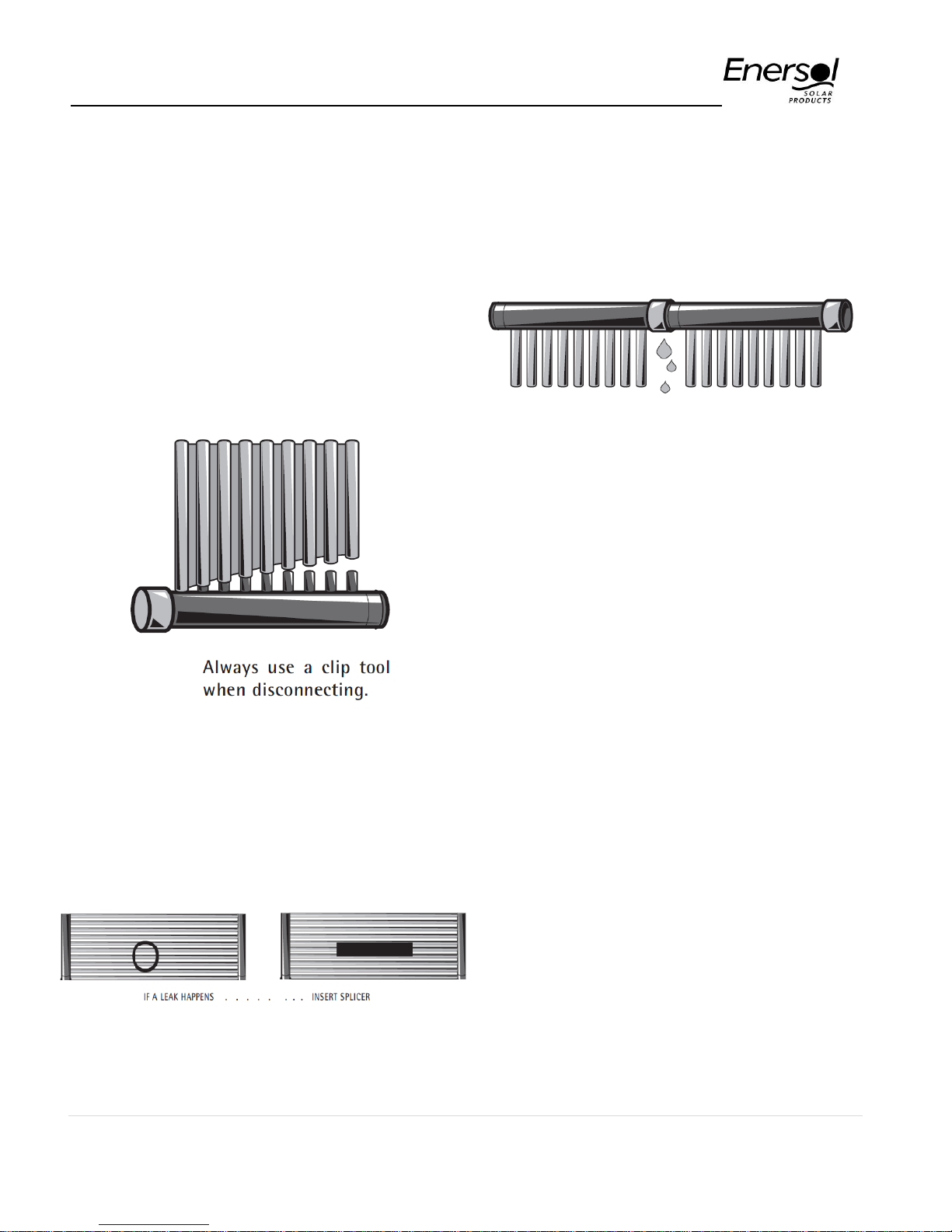
Header or Rubber Replacement
Any header section or length of rubber can be
replaced. To remove the rubber, push the rubber off
with a flat screwdriver. Attach tubes to the headers
by simply sliding them over the nipples. Warm the
ends of the tubes in hot water momentarily. Push
each tube on until it contacts the header and
completely covers the nipple. No clamps are
needed.
Tube Repair
Small isolated holes a splicer can be inserted to
repair small isolated holes.
For repair parts contact your Enersol Dealer or call
1-800-884-6444
If a Section Develops a Leak
Allow 5 or 10 minutes for the O-ring to seat. Replace
O-ring if marked, pinched, nicked or cut. Use O-ring
lubricant as supplied.
WINTERIZATION OF YOUR SOLAR
SYSTEM
Winterization must be done after your pool is closed.
1) Go to the highest point of the solar panels
and pipes and open the top corner end cap.
Remove the opposite bottom corner end
cap. Without disturbing the top and bottom
rows of headers, work your way along the
panels and gently lift the rubber from top to
bottom. If in doubt you can open a section
and drain out excess water. Blowing the
lines with a shop-vac may not remove all of
the water.
2) Open all the end caps at down pipes, pump
house and blow any underground lines.
Make sure that no water remains in any low
pipes, sags in pipe valleys or any part of the
system. Reattach the end cap to ensure
nothing enters header.
3) Valves must be turned to be halfway open or
closed. On motorized valves, turn switch to
TEST and let valve turn halfway. Pull the
electric cord.
15 | P a g e
Page 16

Enersol Pool Panel Installation Guide
4) A general inspection of the roof at this time
is wise. Check for loose lag bolts and
strapping. Remove leaves and debris that
might block the runoff of rain or snow.
SUMMERIZATION OF YOUR
SOLAR SYSTEM
Summerization is done if the system is left for a
prolonged period of inactivity in extreme heat
conditions in excess of 150˚F. This prevents no
circulating water from becoming stagnant and
promoting bacterial growth. The use of a drain down
valve and end cap, and a one way check valve is
necessary. Follow steps for Winterization.
Visit our web site for more
information on repair tips, diagnostic
and troubleshooting.
www.enersol.com
Contents of this Instruction Manual, including
illustrations are the property of EnerWorks Inc. It’s
protected by copyright and shall not be reproduced,
copied, or use for any purpose other than that for
which is given, without EnerWorks written
permission.
16 | P a g e
Page 17
Enersol Pool Panel Installation Guide
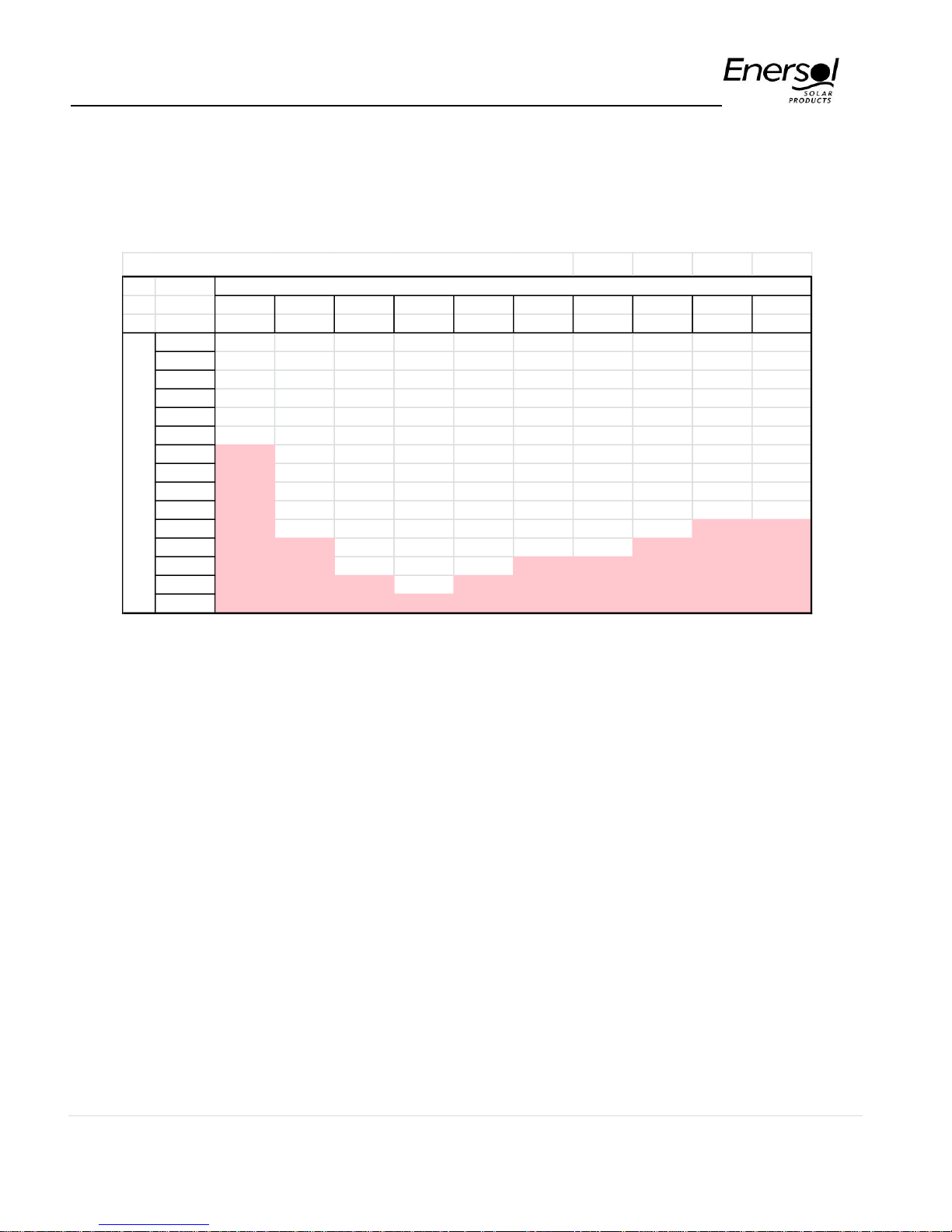
Pressure Losses on (PSI) for 8 feet long Pool Collectors
1 2 3 4 5 6 7 8 9 10
(4 ft) (8 ft) (12 ft) (16 ft) (20 ft) (24 ft) (28 ft) (32 ft) (36 ft) (40 ft)
5 0.24 0.137322 0.10959 0.101136 0.100394 0.103508 0.108825 0.115519 0.123131 0.131386
10 0.90 0.303704 0.262771 0.260394 0.27344 0.294198 0.319362 0.34728 0.377035 0.408074
15 1.88 0.494686 0.45285 0.46885 0.507984 0.558685 0.615996 0.677438 0.741634 0.807758
20 3.06 1.113151 0.677031 0.722774 0.799363 0.891375 0.9922 1.098533 1.208539 1.321114
25 4.49 1.647165 0.933578 1.019853 1.144686 1.288797 1.443925 1.605938 1.772541 1.942357
30 6.15 2.307188 1.626011 1.358448 1.541904 1.748494 1.968303 2.196375 2.429954 2.66739
35 8.04 3.006413 2.135387 2.019137 1.989458 2.268593 2.563151 2.867349 3.177972 3.493094
40 10.14 3.784791 2.704666 2.5602 2.486105 2.847604 3.22673 3.616872 4.014358 4.416985
45 12.46 4.640321 3.370114 3.157516 3.335781 3.484301 3.957608 4.443309 4.937272 5.437019
50 14.98 5.57132 4.049949 3.809879 4.027499 4.177648 4.754579 5.345281 5.945163 6.55147
55 17.72 6.576353 4.784378 4.516246 4.777075 5.247546 5.616608 6.321604 7.036699 7.758862
60 20.65 7.65417 5.572497 5.313589 5.583597 6.135611 6.808544 7.37125 8.210722 9.057905
65 23.79 8.803677 6.413509 6.121963 6.446257 7.085894 7.864632 8.493308 9.46621 10.44747
70 27.12 10.0239 7.306706 6.981243 7.364334 8.097633 8.989292 9.968797 10.80225 11.92653
75 30.65 11.31397 8.251451 7.890837 8.375065 9.17014 10.18178 11.29254 12.21804 13.4942
GPM
Number of Collectors (1 collector = 4 sections of 1 ft each)
Appendix 1:
Pressure Losses in PSI for 8’, 10’ and 12’
Enersol solar panel
Example:
To read values on table match the panel size
(collector) width (top) with the flow rate (left side),
the number at the intersection represent pressure
losses of the panel expressed in PSI. i.e. A pool
solar panel array of 20 feet wide (5 panels) by 8 feet
long will have a pressure loss of 1.54 PSI at 30 GPM
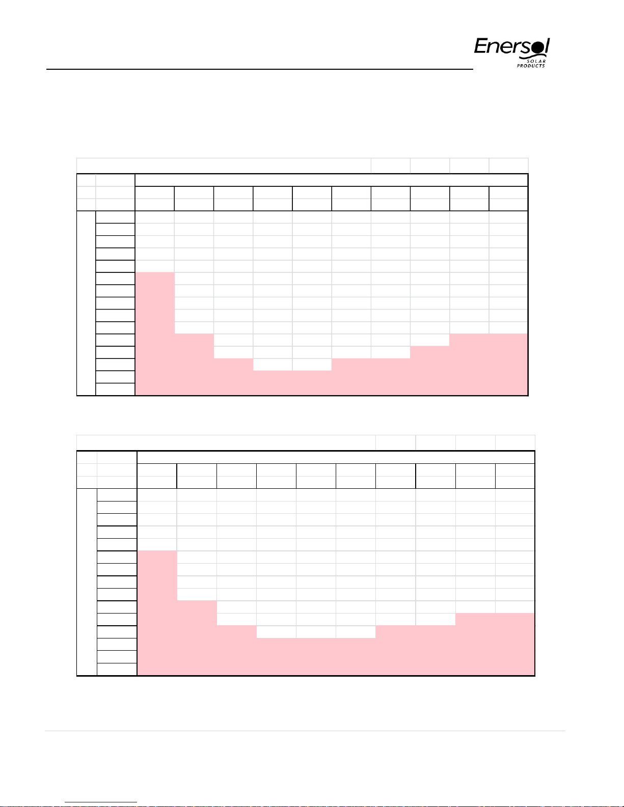
Important: Shaded numbers on the tables indicates
excessive pressure losses on the panels. Care must
be taken not to exceed panel capacity by means of
restricting the flow going to the panels or by splitting
the array as per recommendations. If you have any
questions during the design stage of your solar pool
heating contact us at: 1-800-884-6444.
17 | P a g e
Page 18
Enersol Pool Panel Installation Guide
Pressure Losses on (PSI) for 10 feet long Pool Collectors
1 2 3 4 5 6 7 8 9 10
(4 ft) (8 ft) (12 ft) (16 ft) (20 ft) (24 ft) (28 ft) (32 ft) (36 ft) (40 ft)
5 0.30 0.16624 0.128868 0.115595 0.111961 0.113147 0.117087 0.122748 0.129557 0.137169
10 1.12 0.36154 0.301328 0.289312 0.296574 0.313476 0.335887 0.361739 0.389887 0.419641
15 2.33 0.58144 0.510686 0.512226 0.542685 0.587603 0.640783 0.699126 0.760913 0.825109
20 3.80 1.33001 0.754145 0.78061 0.845632 0.929932 1.025249 1.127451 1.234243 1.344249
25 5.57 1.967622 1.029971 1.092148 1.202522 1.336994 1.485236 1.642085 1.804672 1.971275
30 7.63 2.757556 1.84287 1.445202 1.611307 1.806329 2.017877 2.239751 2.468512 2.702091
35 9.96 3.591458 2.419398 2.190805 2.070428 2.336068 2.620987 2.917955 3.222956 3.533579
40 12.57 4.519394 3.063439 2.777059 2.578642 2.924719 3.292828 3.674708 4.065768 4.463254
45 15.44 5.538961 3.820482 3.424014 3.516125 3.571054 4.031968 4.508374 4.995108 5.489071
50 18.57 6.648144 4.588427 4.130336 4.244358 4.274041 4.837202 5.417576 6.009425 6.609306
55 21.96 7.845221 5.417644 4.894868 5.033296 5.433775 5.707493 6.401129 7.107387 7.822481
60 25.60 9.128698 6.3071 5.763956 5.88196 6.35247 6.974129 7.458003 8.287836 9.127308
65 29.48 10.49726 7.255883 6.637781 6.789481 7.33536 8.055114 8.587291 9.54975 10.52265
70 33.61 11.94974 8.263183 7.566288 7.755086 8.381643 9.206151 10.14047 10.89222 12.0075
75 37.98 13.4851 9.328274 8.548828 8.825432 9.490597 10.42647 11.48624 12.31443 13.58096
Number of Collectors (1 collector = 4 sections of 1 ft each)
GPM
Pressure Losses on (PSI) for 12 feet long Pool Collectors
1 2 3 4 5 6 7 8 9 10
(4 ft) (8 ft) (12 ft) (16 ft) (20 ft) (24 ft) (28 ft) (32 ft) (36 ft) (40 ft)
5 0.36 0.195158 0.148147 0.130054 0.123529 0.122787 0.125349 0.129978 0.135983 0.142953
10 1.34 0.419376 0.339885 0.31823 0.319709 0.332755 0.352411 0.376198 0.402739 0.431209
15 2.78 0.668193 0.568521 0.555603 0.577387 0.616521 0.665569 0.720815 0.780191 0.84246
20 4.53 1.546869 0.83126 0.838446 0.8919 0.968489 1.058298 1.156369 1.259948 1.367383
25 6.64 2.288079 1.126364 1.164443 1.260358 1.38519 1.526548 1.678233 1.836803 2.000193
30 9.10 3.207924 2.059728 1.531956 1.68071 1.864165 2.06745 2.283128 2.507069 2.736793
35 11.89 4.176504 2.703408 2.362474 2.151398 2.403543 2.678823 2.968561 3.267939 3.574064
40 15.00 5.253996 3.422212 2.993918 2.671179 3.001833 3.358926 3.732544 4.117177 4.509523
45 18.43 6.4376 4.27085 3.690512 3.696469 3.657808 4.106329 4.57344 5.052944 5.541123
50 22.16 7.724968 5.126905 4.450793 4.461217 4.370435 4.919825 5.48987 6.073687 6.667142
55 26.20 9.11409 6.05091 5.273491 5.289517 5.620004 5.798378 6.480653 7.178075 7.886101
60 30.54 10.60323 7.041702 6.214324 6.180322 6.569329 7.139714 7.544757 8.364951 9.196711
65 35.17 12.19084 8.098256 7.1536 7.132706 7.584826 8.245596 8.681275 9.633291 10.59784
70 40.10 13.87558 9.219661 8.151334 8.145839 8.665653 9.42301 10.31213 10.98219 12.08847
75 45.32 15.65623 10.4051 9.206819 9.2758 9.811054 10.67116 11.67994 12.41083 13.66771
Number of Collectors (1 collector = 4 sections of 1 ft each)
GPM
Appendix 1: (continued)
Pressure Losses in PSI for 8’, 10’ and 12’
Enersol solar panel
18 | P a g e
 Loading...