

Enersafe ESOL T-E 6kVa, ESOL T-E 10kVa, ESOL T-E 6kVaL, ESOL T-E 10kVaB, ESOL T-E 10kVaS User Manual
Page 1

User Manual
UPS ESOL T-E
6 y 10 kVA
Page 2
User Manual
Foreword
Summaries
Alerts you to a medium or low risk hazard that could, if not
you to a potentially hazardous situation that could, if not
avoided, result in equipment damage, data loss, performance
Thank you for choosing UPS!
This document gives a description of the (6-10kVA) UPS(hereinafter referred to as UPS),
including the features, performance, appearance, structure, working principles, installation,
operation, maintenance, transportation and storage, etc.
lease save the manual after reading, in order to consult in the future.
P
The figures in this manual are just for reference, for details please see the actual product.
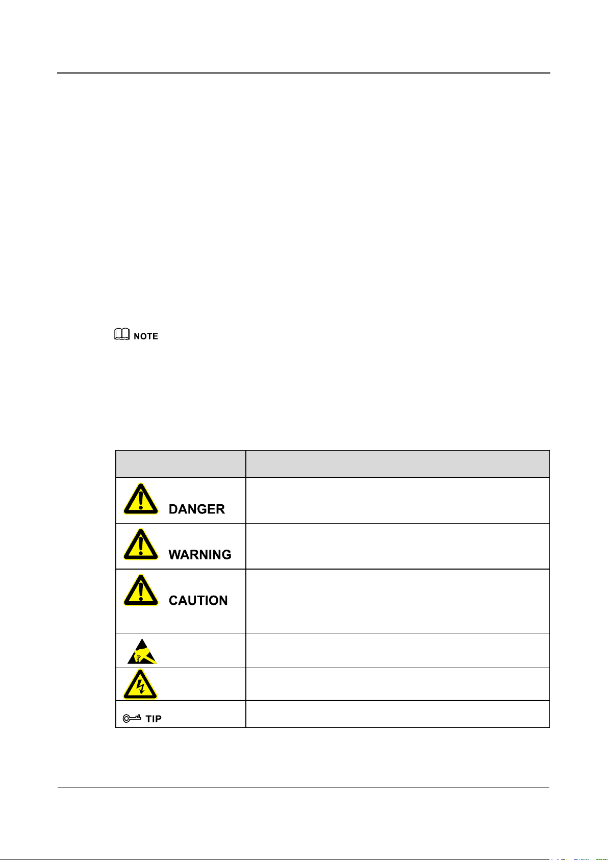
Symbol Conventions
The manual quotes the safety symbols, these symbols used to prompt users to comply with safety
Foreword
matters during installation, operation and maintenance. Safety symbol meaning as follows.
Symbol Description
Alerts you to a high risk hazard that could, if not avoided, result in
serious injury or death.
avoided, result in moderate or minor injury.
Alerts
deterioration, or unanticipated results.
Anti-static prompting.
Be care electric shock prompting.
P
rovides a tip that may help you solve a problem or save time.
i
Page 3

Foreword
User Manual
Symbol Description
information to emphasize or supplement
Product standard: Q/ZZKJ 001
Change History
Changes between document issues are cumulative. The latest document issue contains all the changes
made in earlier issues.
Issue 001 (2017-09-01)
First issue.
Provides additional
important points in the main text.
ii
Page 4

User Manual
Contents
Contents
1 Safety Description......................................................................................................................... 1
1.1 Safety Announcements ..................................................................................................................................... 1
1.1.1 Use Announcement s ................................................................................................................................ 1
1.1.2 Battery Announcements .......................................................................................................................... 2
1.1.3 ESD Protection ........................................................................................................................................ 3
1.2 Working Environment Requirements ............................................................................................................... 3
2 Overview ......................................................................................................................................... 4
2.1 Product Intro..................................................................................................................................................... 4
2.1.1 Model Meaning ....................................................................................................................................... 4
2.1.2 Features ................................................................................................................................................... 4
2.2 Appearance ....................................................................................................................................................... 5
2.2.1 Operation Panel ....................................................................................................................................... 7
2.2.2 Rear Panel View ...................................................................................................................................... 9
2.2.3 Intelligent Slot ....................................................................................................................................... 13
2.2.4 EPO Connect or ..................................................................................................................................... 14
2.2.5 RS232 Communication ......................................................................................................................... 14
2.3 Working Principl es ......................................................................................................................................... 15
2.3.1 Working Mode ...................................................................................................................................... 15
2.3.2 UPS Parameters Setting ........................................................................................................................ 18
3 Installation.................................................................................................................................... 20
3.1 Unpacking a nd Checking ............................................................................................................................... 20
3.1.1
6kVA(L)/ 10kVA(/B) ...........................................................................................................................20
3.1.2 6kVA/10kVA(S) .................................................................................................................................... 20
3.2 Installation Preparation .................................................................................................................................. 22
3.2.1 Input Breaker Selection ......................................................................................................................... 22
3.2.2 Selection of the Cross-sectional Area of Wire....................................................................................... 23
3.3 Electrical Connection ..................................................................................................................................... 23
iii
Page 5

Contents
User Manual
3.3.3 6kVA/6kVA(L) ...................................................................................................................................... 26
3.3.4 10kVA/10kVA(S)/10kVA(/B) ............................................................................................................... 28
3.3.5 Intelligent Slot Installation .................................................................................................................... 31
4 Operation and Maintenance ..................................................................................................... 32
4.1 Check Before Startup ..................................................................................................................................... 32
4.2 Startup Operation ........................................................................................................................................... 32
4.2.2 6kVA(L)/ 10kVA(/B) /10kVA(S) .......................................................................................................... 33
4.3 Shutdown Op eration ....................................................................................................................................... 33
4.3.2 6kVA (L)/10kVA (/B) /10kVA(S) .......................................................................................................... 33
4.4 Parallel System Operation .............................................................................................................................. 34
4.4.1 Start Parallel System ............................................................................................................................. 34
4.4.2 Close Parallel System............................................................................................................................ 34
4.4.3 Remove Faulty UPS from Parallel System ........................................................................................... 35
4.4.4 Add New UPS into Parallel System ...................................................................................................... 35
4.4.5 Redundancy Funciton of Parallel System ............................................................................................. 35
4.5 Periodic Preventative Maintenance ................................................................................................................ 35
4.6 Battery Maintenance ...................................................................................................................................... 36
4.7 Maintenance Byass Mode(Only for UPS with Maintenance Bypass) ............................................................ 36
4.8 Troubleshooting .............................................................................................................................................. 37
5 Package, Transportation, Storage ............................................................................................. 41
5.1 Package .......................................................................................................................................................... 41
5.2 Transportation ................................................................................................................................................ 41
5.3 Storage ........................................................................................................................................................... 41
Appendix A Technical Specifications ........................................................................................ 42
Appendix B Acronyms and Abbreviations ............................................................................... 46
iv
Page 6
User Manual
1 Safety Description
1 Safety Description
This chapter mainly describes the safety announcements. Prior to performing any work on the device,
please read the user manual carefully, follow the operation and installation instructions and observe
all danger, warning and safety information, which is to avoid human injury and device damage by
irregular operations.
1.1 Safety Announcements
This section mainly describes the safety announcements when operation and maintenance. For details,
please refer to safety description in the relevant chapters.
Before using UPS, please read the announcements and operation instructions in this section carefully
to avoid accident.
The promptings in the user manual, such as "Danger", "Warning", "Caution", etc. don't include all
safety announcements. They are just only the supplement of safety announcements when using UPS.
Any device dama ge c au s ed by violating the general safety operation requirements or safety standards
of design, production, and usage will be out of warranty range.
1.1.1 Use Announcements
There exists high temperature and high voltage inside UPS. When using UPS, please strictly comply
with all warnings and operation instruments on the UPS and in the user manual.
1
Page 7
1 Safety Description
User Manual
Only authorized professionals are allowed to open the UPS chassis to avoid electric shock. Otherwise,
if it causes UPS failure, it is out of the guarantee range.
UPS is a class A product. When it is applied to residential building, additional measures should be
took to prevent harassment.
Ensure that no liquid or other foreign objects can enter into UPS.
UPS must be grounded well.
If UPS has to be moved, rewired or maintained, it must disconnect all electrical connection, suc
s AC power, battery power, etc. to isolate power. It can't perform any work on the UPS until
a
UPS is powered off completely(≥10min). Otherwise, the output may have electricity, which may
cause electric shock.
When dismantling fan, do not put fingers or tools into the rotating fan until it has stoppe
orking to avoid device damage or human injury.
w
Do not connect unbalance load, half-wave rectification load or inductive load in the output of
UPS, such as air-condition, blower, starter, electric drill, motor, daylight lamp, etc.
In case of fire, use dry powder extinguisher to put out the fire. If you use liquid fire extinguisher
i
t may cause electric shock.
1.1.2 Battery Announcements
h
d
,
2
Please use specified model battery!Non-specified model battery will lead to UPS damage.
Only authorized professional can replace battery. When operation, take off conductive objects,
such as watch, bracelet, bangle, ring, etc., wear rubber shoes and gloves and use tools with
insulated handle.
Page 8

User Manual
1 Safety Description
Don't put tools or other conductive objects on the battery.
It's prohibited to connect the anode of bat tery with the cathode of battery or connect them
reversely, which is to avoid fire or electric shock.
Before connecting or disconnecting the battery terminals, disconnect charger first.
The battery must be with the same type, model, and manufacturer.
Battery should be kept away from fire source or all electrical equipments that may easily caus
sp
ark avoid human injury.
Don't open or destroy battery. The electrolyte in the battery includes some dangerous objects,
such as strong acid, which will be harmful to skin and eyes. If it is careless to touch the
electrolyte, clean it by a lot of water immediately and then check it in the hospital.
The waste battery should be disposed according to the local regulations.
1.1.3 ESD Protection
To prevent human electrostatic damaging sensitive components(such as circuit board), make sure that
to wear a anti-static wrist strap before touching sensitive components, and the other end of wrist strap
is well grounded.
e
1.2 Working Environment Requirements
Don't install UPS where it would be exposed to direct sunlight, in rain or in moist environments.
Don't install UPS where it is with conductive metal dust or nearby heater.
Generally, the working temperature is -5℃~+40℃ and the relative humidity is 0%RH~
95%RH that is with no condensation(The recommended working temperature is 20℃~25℃ and
the recommended relative humidity is about 50%).
Put UPS in the flat floor without vibration and the vertical gradient is less than 5°. Kee
v
entilation around UPS. The clearance between the rear or the side of UPS and adjacent devices
or wall should be at least 300mm~500mm. Poor ventilation will rise temperature inside UPS,
which will reduce the working life of inner components and then affect the working life of UPS.
The recommended altitude is lower than 1000m. If exceeding 1000m, it need to decrease th
r
ated power according to GB3859.2-93.
p good
e
3
Page 9

2 Overview
User Manual
2 Overview
This chapter mainly describes the model meaning, features, structure and working principle, etc.
2.1 Product Intro
(1-10kVA ) U PS are with all high frequency, pure online, double-conversion, intelligent features.
They are the perfect power security for file server, enterprise server, center server, mirco-computer,
concentrator, telecom system, data center and others that require high quality power protection. They
are widely applied to the many key business areas, such as post, finance, network, stock, railway, etc.
(1-10kVA) UPS are with the single-phase AC input and single-phase AC output. Each series UPS
includes standard and long backup models.
2.1.1 Model Meaning
UPS that the output power is less than 6kVA
"L" means long backup model. If there is no "L" symbol, it means standard model.
UPS that the output power is not less than 10kVA
"/B" means that the product can be used in the parallel system; "S" means standard model. If th ere is
no "S" symbol, it means long backup model.
2.1.2 Features
Intelligent RS232 communication
Through the RS232 standard data port and UPS power management software, it can realize the three
remote function between the computer and UPS, monitor the running and electrical data of UPS on
the computer, perform ON/OFF operation remotely and support SNMP network adaptor (external,
connect with UPS through RS232 port), which makes UPS be a network new member.
High input power factor
Adopt the advanced active PFC technology, which eases load in the power grid. It is the new
generation green power.
4
Page 10
User Manual
2 Overview
High cost performance
Adopt many kinds of power conversations and high frequency PWM technologies, which is with
high efficiency, small volume, light weight, improves the running reliability and reduces cost.
Perfect protection
Equipped with the functions, such as output over-voltage protection, battery under-voltage protection,
input over-voltage protection, triple over-current protection, etc. and solve the problems of the high
frequency UPS, such as poor adaptability in the power grid and weak anti-impact ability.
Low mains input voltage
Adopt the independent rapid detection technology. When the mains input voltage is 120V, which is
the lower limit, the battery still doesn't discharge. Therefore, in the mains mode, all output power gets
from the power grid, which is to ensure the battery is still in the 100% energy storage status, reduce
the battery discharge times and prolong the working life.
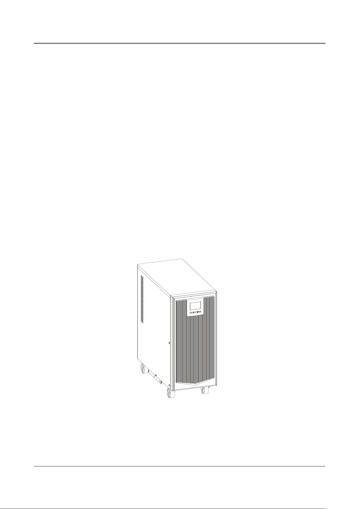
2.2 Appearance
Figure2-3 Appearance of 6kVA/10kVA
5
Page 11
User Manual
2 Overview
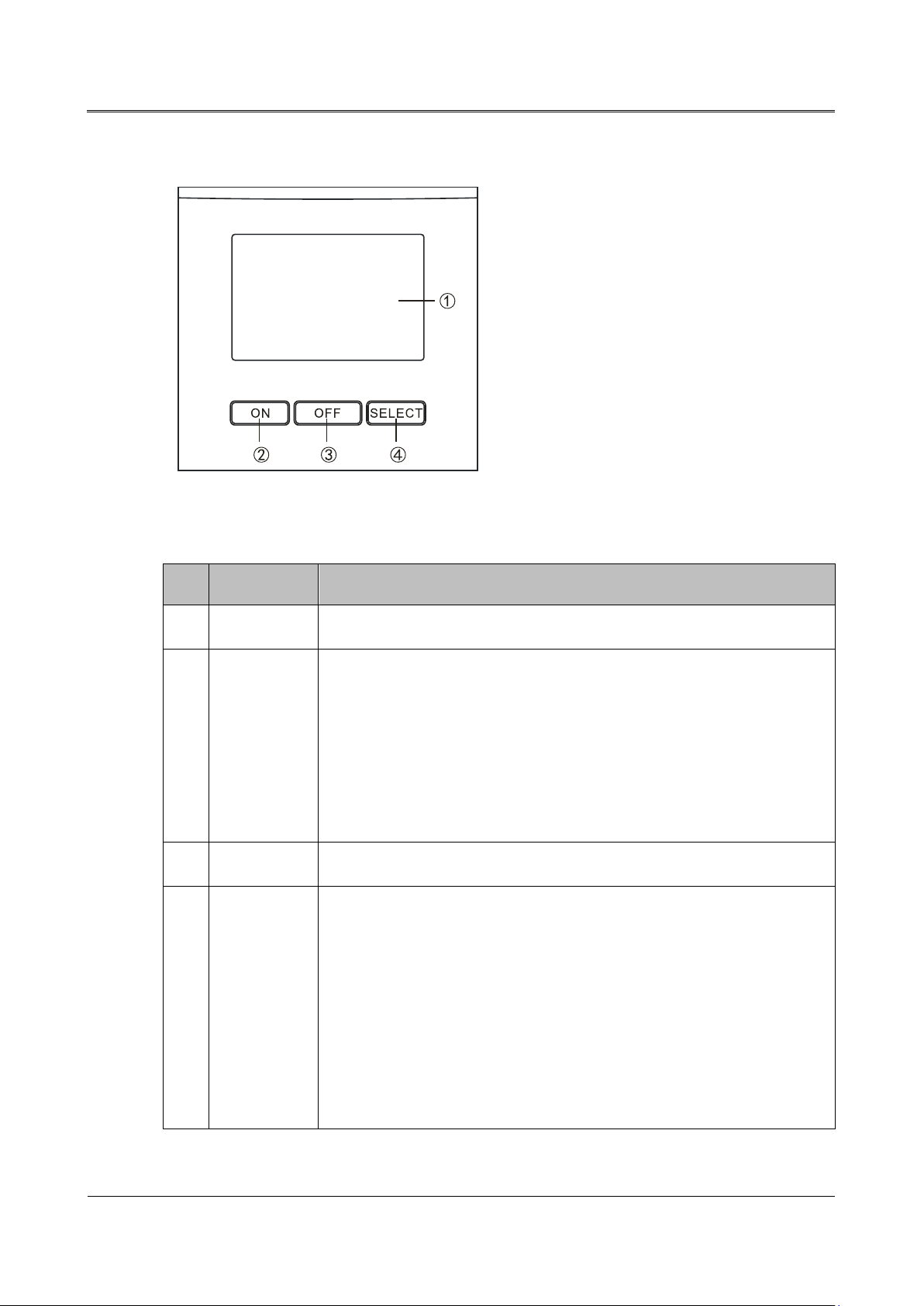
2.2.1 Operation Panel
transfer the display information, such as
igure2-4 Operation panel
F
Table2-1 The illustration of operation panel
No. Name Illustration
1
○
LCD Display the working status and setting of UPS.
When UPS is off, press and hold "ON" button for 1s to turn on UPS.
When UPS is on and works in the mains mode, press and hold "ON
but
2
○
"ON" button
In the set page, press and hold "ON" button for 1s to confirm the setting.
3
○
"OFF" button When UPS is on, press and hold "OFF" button for 1s to turn off UPS.
Press "SELECT" button to
4
○
"SELECT"
button
Press and hold "SELECT" button for 5s to enter the set page. Then press
ton for 3s to do the battery test. When UPS works in the battery
mode, press and hold "ON" button for 3s to silence the buzzer(cancel
the mains abnormal alarm).
output voltage, output frequency, input voltage, input frequency, battery
voltage, inner temperature, load percentage, fault information, etc.
"SELECT" button to transfer the setting information, such as PAR/SGL
mode(only available for parallel system), ECO/INV mode or the
"
inverting output voltage that is 208V/220V/230V/240V, and press "ON"
button to confirm the setting.
7
Page 12
2 Overview
User Manual
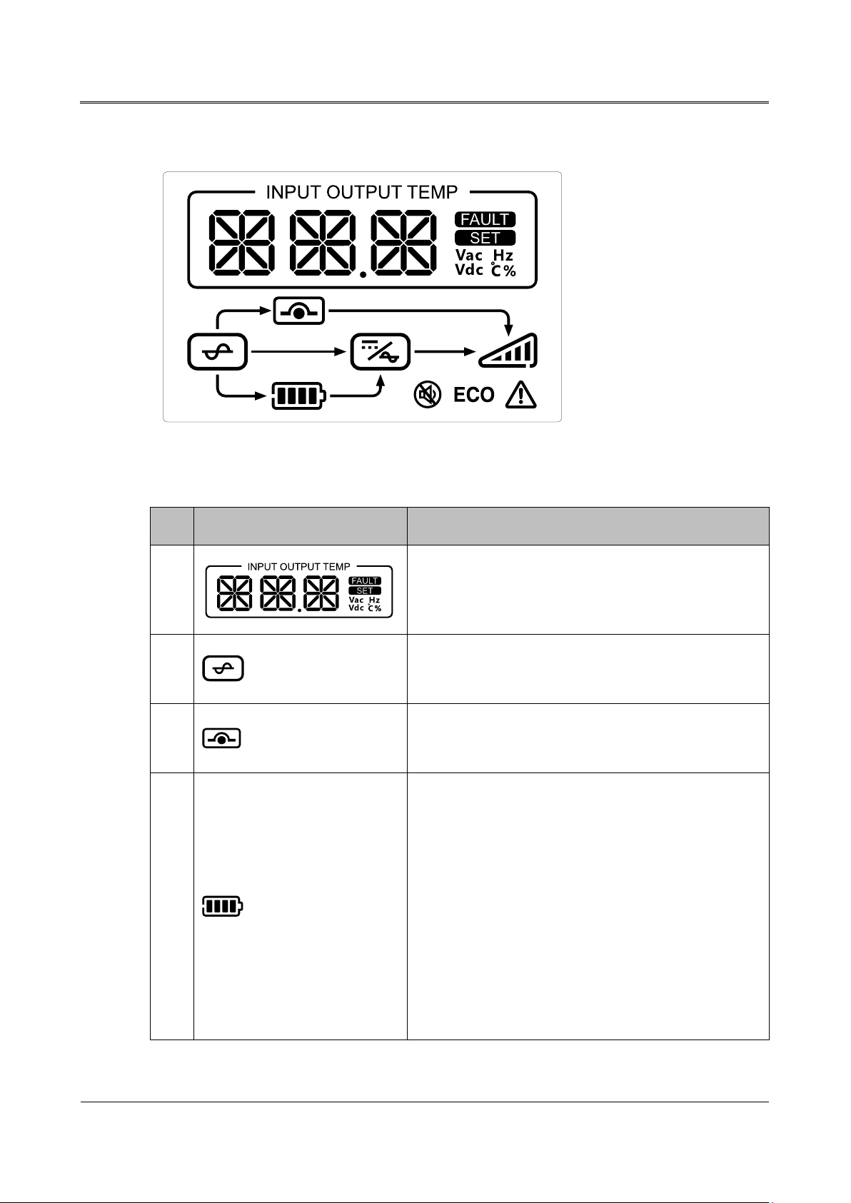
LCD panel
It shows input voltage, input frequency, output voltage,
igure2-5 LCD panel
F
Table2-2 The illustration of LCD panel
No. Icon Illustration
1
2
3
4
output frequency, load percent, temperature, fault code,
parameters or working mode, etc.
M
ains icon
ON: Mains input is normal.
Bypass icon
ON: UPS works in the bypass mode.
attery icon: four energy bars
B
1. When the energy bars light on from left to right again
and again, it indicates battery is in charge.
2. When all energy bars are on, it indicates battery is
fully charged.
3. When all energy bars flicker, it indicates battery is
over-voltage.
4. When all energy bars are off and the frame flickers, it
8
indicates battery is about to run out.
Page 13
User Manual
2 Overview
No. Icon Illustration
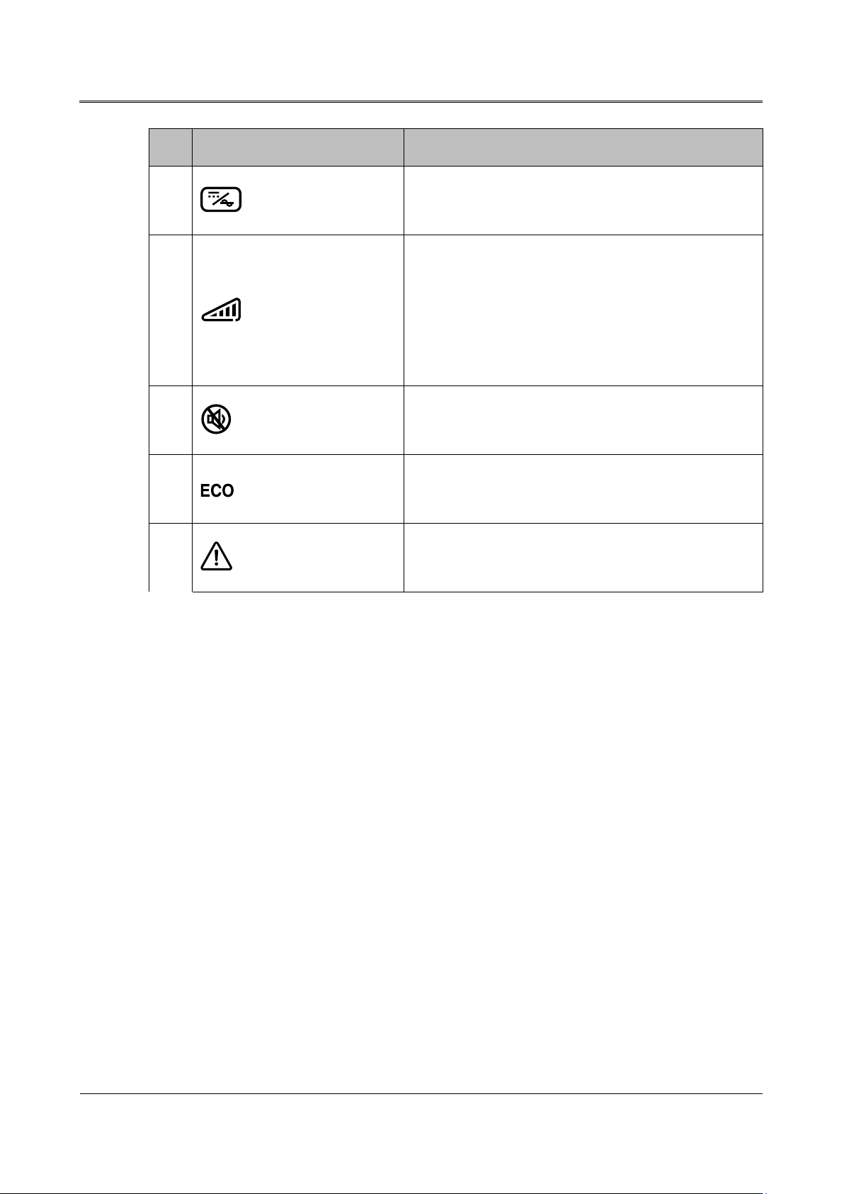
Inverting icon
5
ON: Inverter is working.
d icon: four energy bars
Loa
1. The energy bars from left to right indicates the load
6
level.
2. When all energy bars flicker, it indicates load is too
large.
Silence icon
7
ON: Buzzer is in the silence status.
ECO mode icon
8
ON: UPS works in the ECO mode.
Alarm icon
9
ON:UPS failure.
9
Page 14
User Manual
2 Overview
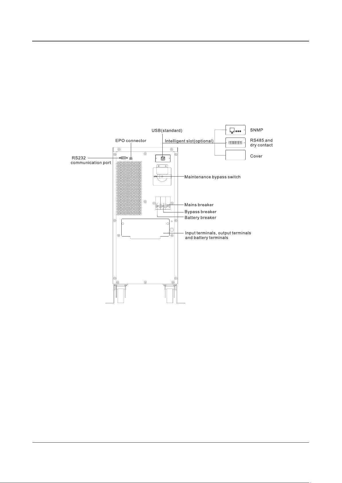
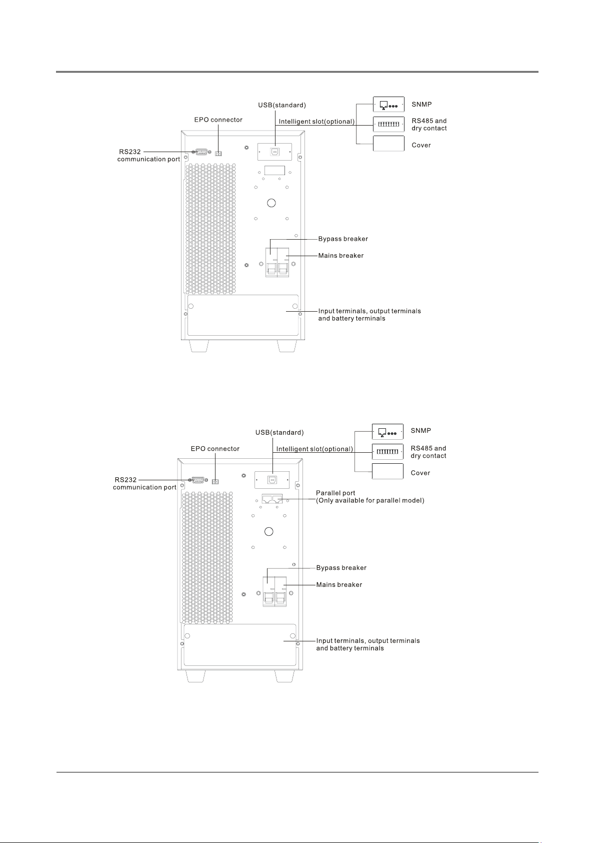
2.2.2 Rear Panel View
6kVA/6kVA(L)
6kVA standard model
Figure2-8 Rear panel of 6kVA
6kVA(L) long backup model
11
Page 15
2 Overview
User Manual
F
igure2-9 Rear panel of 6kVA(L)
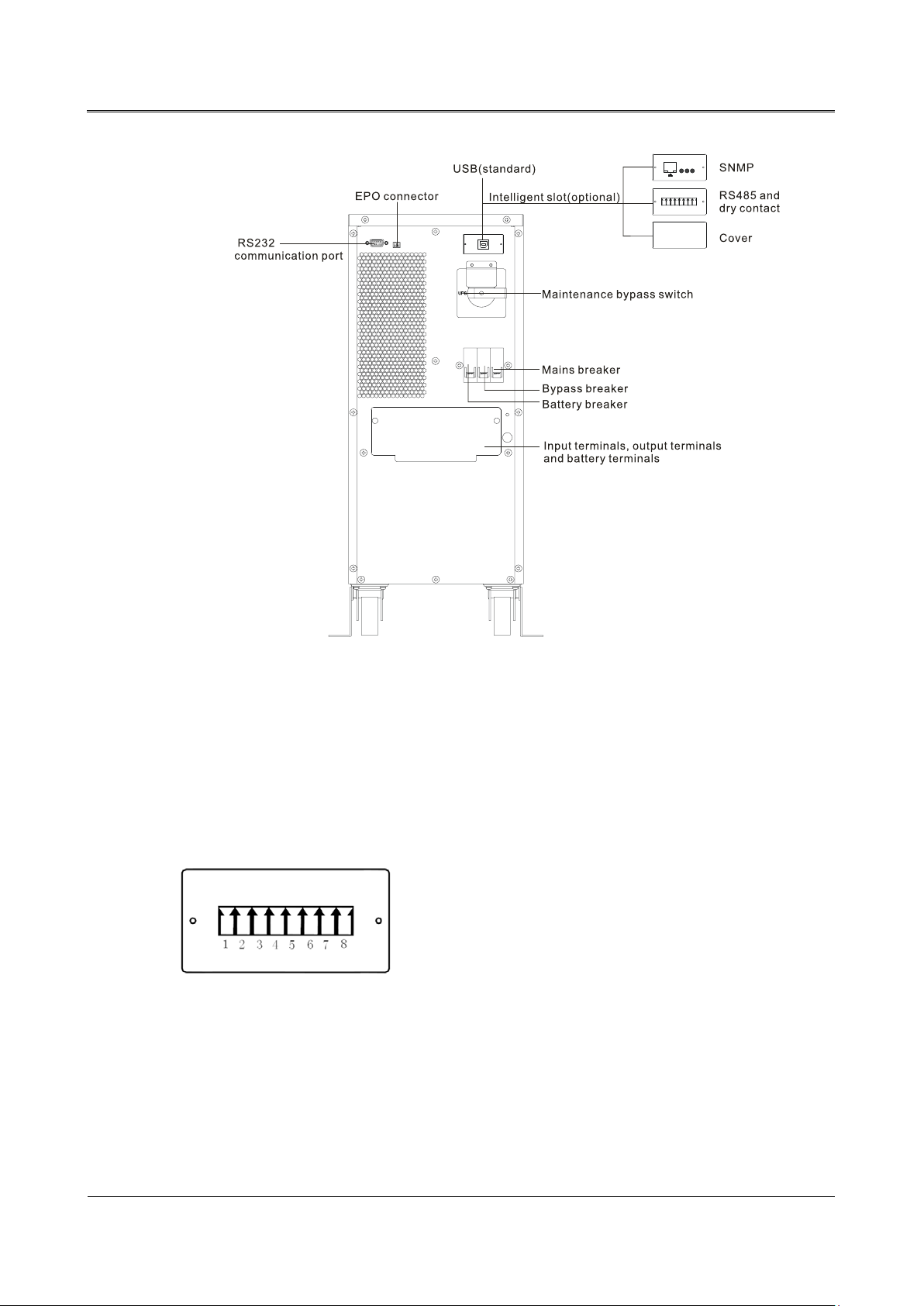
10kVA(/B) /10kVA(S)
12
igure2-10 Rear pa nel of 10kVA(/B)
F
Page 16
User Manual
2 Overview
igure2-11 Rear panel of 10kVA(S)
F
2.2.3 Intelligent Slot
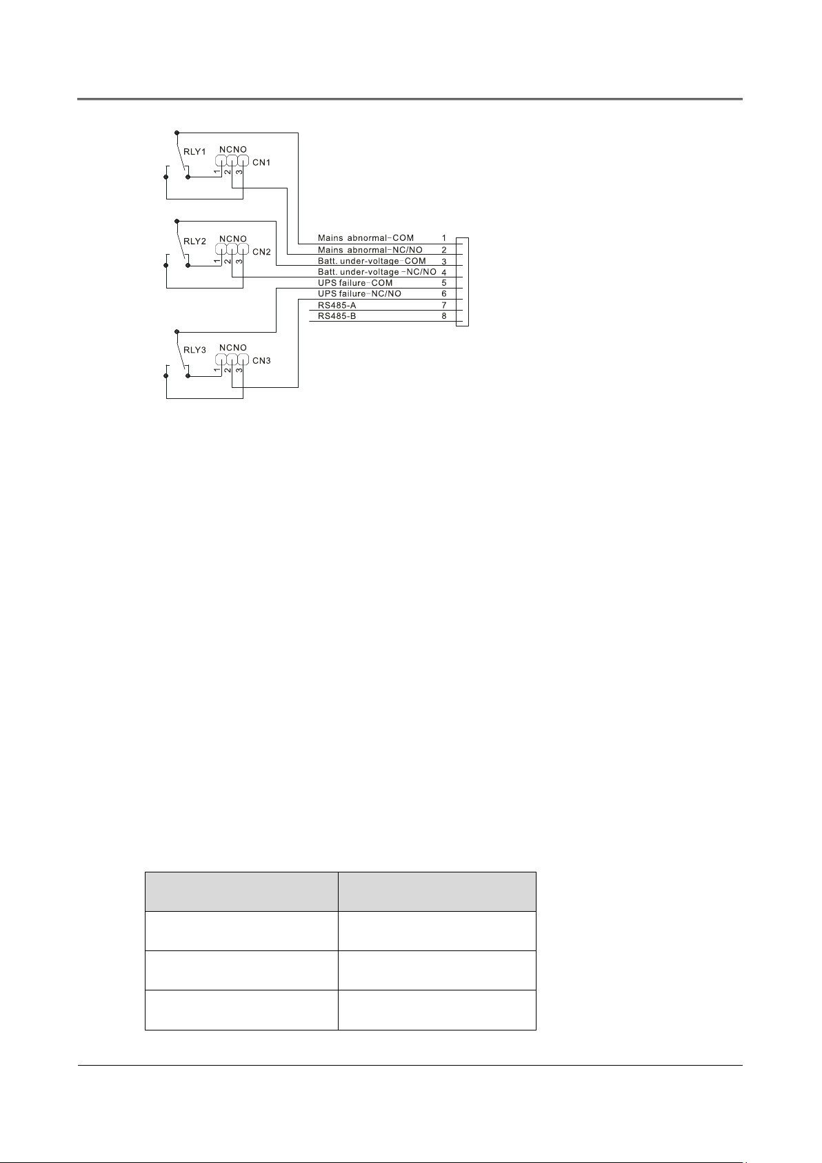
RS485 and dry contact(optional)
The pin sequence and pin definition of RS485 and dry contact is as shown in Figure2-14 and
Figure2-15.
igure2-12 RS485 and dry contact
F
13
Page 17
2 Overview
User Manual
igure2-13 Pin definition of RS485 and dry contact
F
The illustration of dry contact is as below:
1. CN1, CN2, CN3 determine that dr y contact output signal is normal open or normal close. In
default, dry contact output signal is normal close, that is PIN1 connects with PIN2. If one route
signal needs to set to normal open, connect PIN2 with PIN3.
2. The requirements for input signal of dry contact: the voltage should be less than 60Vdc or
42Vac RMS and the current should be less than 1.25A.
2.2.4 EPO Connector
When connecting two ports in the EPO connector together, UPS will close output. If it needs to
recover output, disconnect two ports in the EPO connector and power UPS off, and then restart UPS.
2.2.5 RS232 Communication
The corresponding pin relationship between RS232 port of UPS and RS232 port of PC is as shown in
Table2-3.
Table2-3 The corresponding pin relationship between RS232 port of UPS and RS232 port of PC
RS232 port of UPS RS232 port of PC
9 (3) 2 (receiving end)
6 (2) 3 (transmitting end)
7 (5) 5 (grounding end)
14
Page 18
User Manual
2 Overview
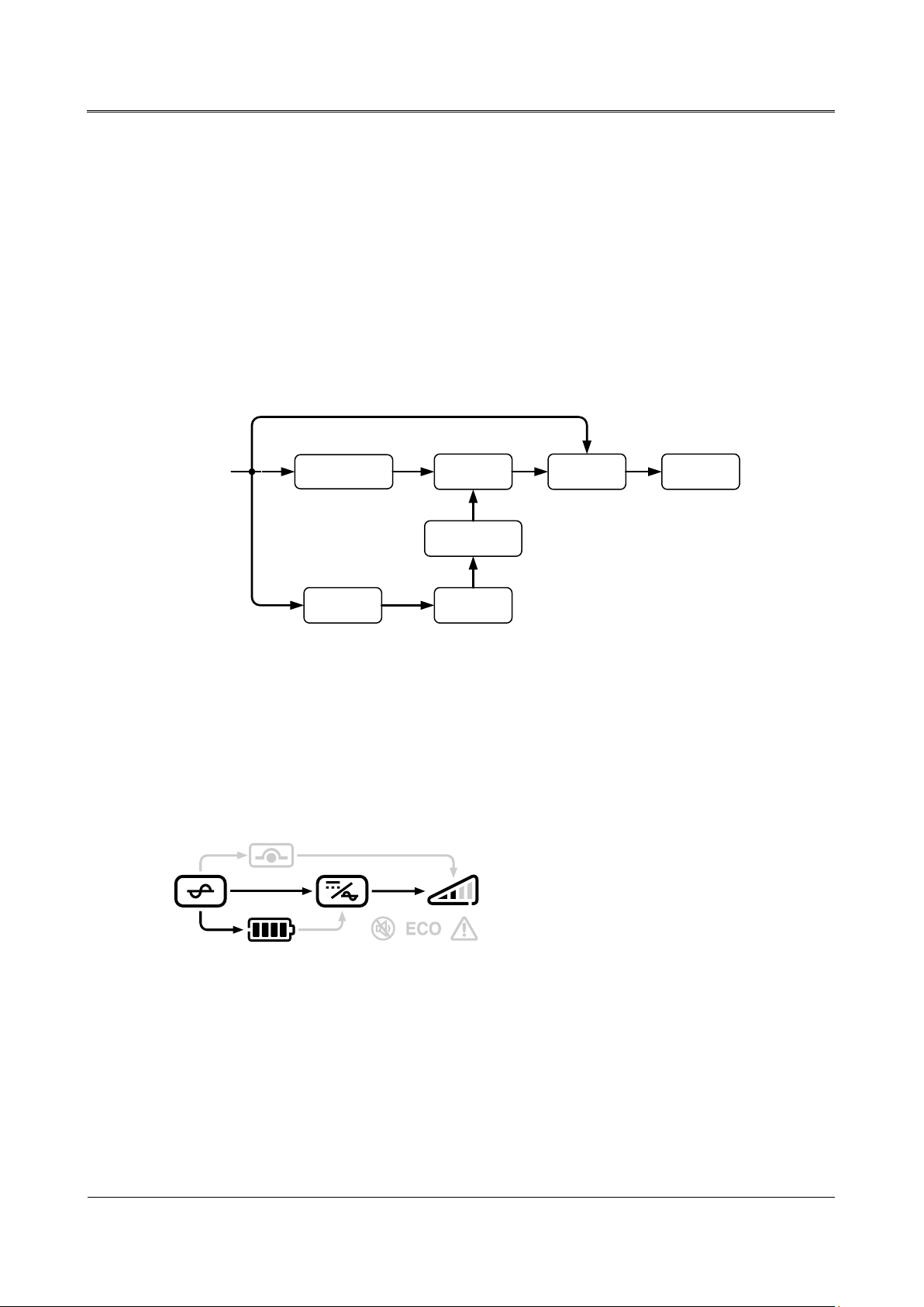
2.3 Working Principles
Mains
220Vac
PFC AC/DC
DC/AC
Transfer
switch
Load
DC/DC
Battery
Charger
When the mains is normal, the input of UPS (1-10kVA) series converts into the ±360V steady DC
voltage through PFC, which supplies power for DC/AC inverter to output steady 220V AC and
charges battery at the same time. When the mains is abnormal, the battery will boost into the ±360V
DC voltage for DC/AC inverter through DC/DC.
The working principles of UPS (1-10kVA) series is as shown in Figure2-16. The DC/AC inverter
adopts half bridge structure and the DC/DC boost adopts the push-pull circuit or boost circuit. PFC is
the correction circuit for active power factor.
igure2-14 The working principle of UPS (1-10kVA) series
F
2.3.1 Working Mode
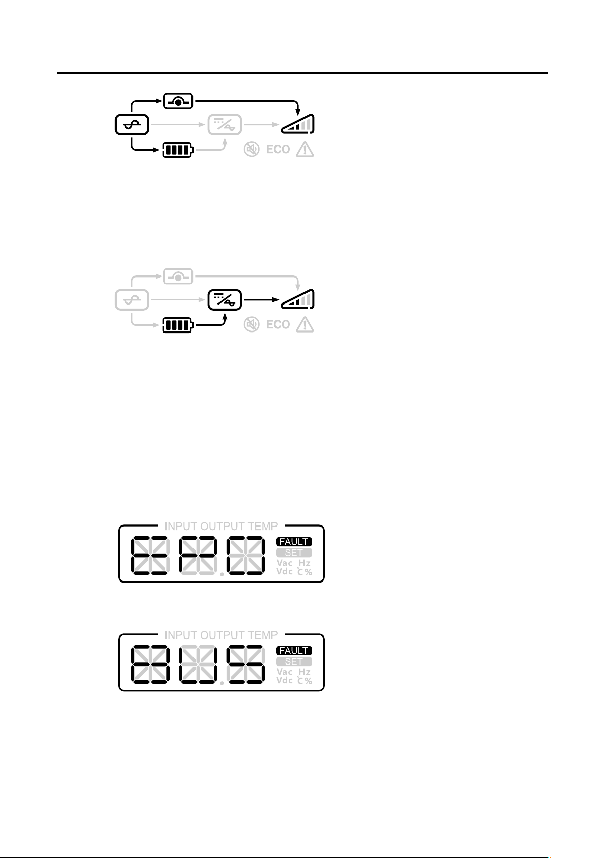
Mains mode
When the mains works, UPS will work in the mains mode and charge battery. The LCD display is as
shown in Figure2-17.
Figure2-15 Mains mode
Bypass mode
UPS works in the bypass mode and charges battery. The LCD display is as shown in Figure2-18.
15
Page 19
2 Overview
User Manual
igure2-16 Bypass mode
F
Battery mode
When the mains is abnormal, it will work in the battery mode. The LCD display is as shown
Figure2-19.
Figure2-17 Battery mode
Fault status
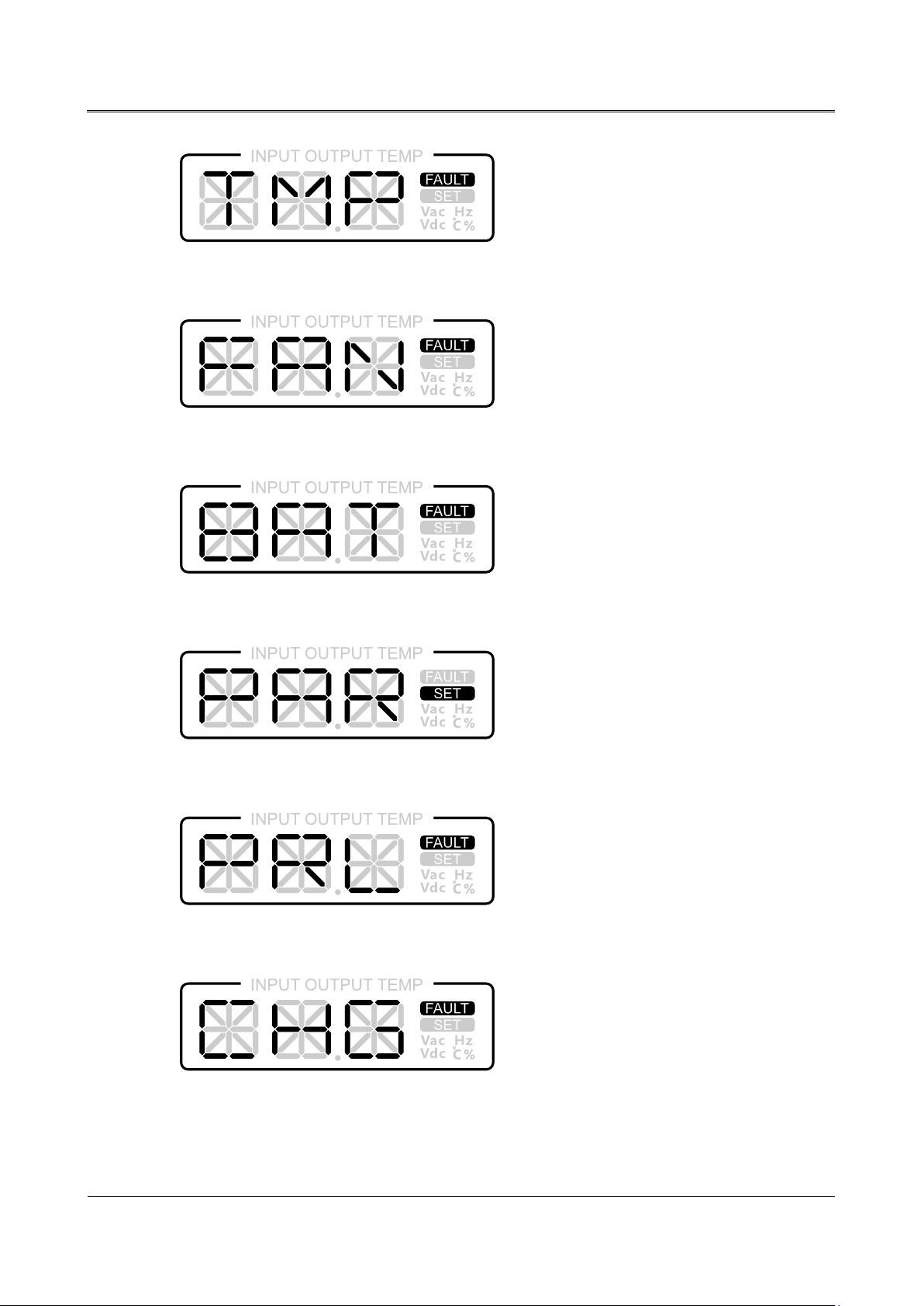
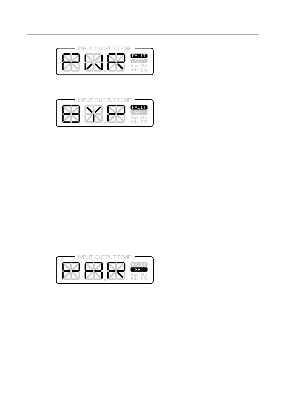
UPS faults include: EPO protection, busbar voltage fault, IGBT over-temperature fault, fan
fault(including fan blocked, fan damage, etc.), output fault(including output overload protection,
output short-circuit, etc.), battery fault(including battery over-voltage protection, battery
under-voltage protection, etc.), parallel wire disconnected fault, parameter error, charger
fault(including charger over-temperature, charger short-circuit, etc.), bypass fault, inner power fault,
etc. The corresponding fault status displayed in the LCD is as shown in Figure2-20 to Figure2-29.
F
igure2-18 EPO protection
F
igure2-19 Busbar voltage fault
16
Page 20
User Manual
2 Overview
igure2-20 IGBT over-temperature fault
F
igure2-21 Fan fault
F
igure2-22 Battery fault
F
Figure2-23 Parameters error
Figure2-24 Parallel wire disconnected fault
Figure2-25 Charger fault
17
Page 21
2 Overview
User Manual
igure2-26 Inner power fault
F
igure2-27 Bypass fault
F
2.3.2 UPS Parameters Setting
Press and hold "SELECT" button for 5s to enter the set page. Then press "SELECT" button to
transfer the setting information, such as PAR/SGL mode(only available for parallel system),
ECO/INV mode or the inverting output voltage that is 208V/220V/230V/240V, and press "ON"
button to confirm the setting.
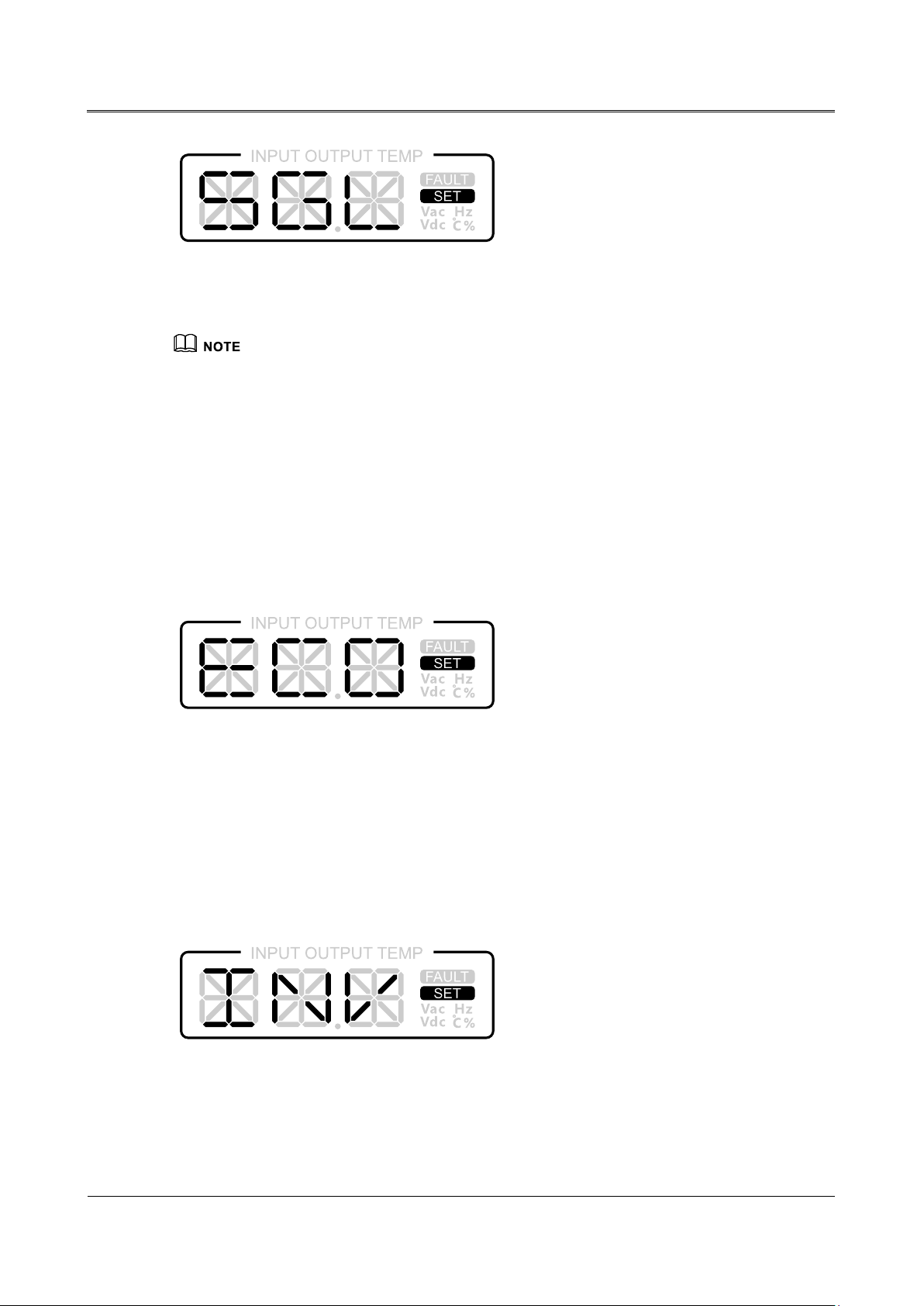
PAR mode(only available for parallel system)
"PAR" set page: When system works in the SGL mode and it has to set to PAR mode, in the set page,
three characters "PAR" flicker. If you confirm the selection, press and hold "ON" button more than 1s
to q uit the set page, the settin g is successful. If you aren't sure the selection, it will quit the se t page
20s later automatically. In the PAR mode, the LCD display is as shown Figure2-30.
F
igure2-28 PAR mode
SGL mode(only available for parallel system)
"SGL" set pa g e : When system works in the PAR mode and it has to set to SGL mode, in the set page,
three characters "SGL" flicker. If you confirm the selection, press and hold "ON" button more than 1s
to q uit the set page, the settin g is successful. If you aren't sure the selection, it will quit the se t page
20s later automatically. In the SGL mode, the LCD display is as shown Figure2-31.
18
Page 22
User Manual
2 Overview
ECO mode
igure2-29 SGL mode
F
PAR mode and SGL mode are only available for parallel system. It only can show PAR mode or SGL
mode alternatively in the LCD. When it is in the PAR mode, it shows three characters "SGL" in the set
page. It can set the working mode to the SGL mode. When it is in the SGL mode, it shows three
characters "PAR" in the set page. It can set the working mode to the PAR mode.
"ECO" set page: In the set page, three characters "ECO" flicker. If you confirm the selection, press
and hold "ON" button more than 1s to quit the set page, the setting is successful. If you aren't sure the
selection, it will quit the se t page 20s later automatically. In the ECO mode, the LCD display is as
shown Figure2-32.
INV mode
F
igure2-30 ECO mode
"INV" set page: In the set page, three charters "INV" flicker. If you confirm the selection, press and
hold "ON" button more than 1s to quit the set page, the se tting is successful. If you aren't sure the
selection, it will quit the se t page 20s later automatically. In the INV mode, the LCD display is as
shown Figure2-33.
Figure2-31 INV mode
The setting of the inverting output voltage that is 208V/220V/230V/240V is the same to the above
method.
19
Page 23

3 Installation
User Manual
3 Installation
This chapter mainly describes installation, including the unpacking and checking, installation
preparation, electrical connection, etc.
3.1 Unpacking and Checking
3.1.1 6kVA(L)/ 10kVA(/B)
Besides 6kVA/10kVA(S) standard model, the package of the UPS (6-10kVA) series is carton.
Unpacking UPS and conduct t he following items:
nspect the appearance for shipping damage. If any shipping damage is found, report it to the
I
carrier immediately.
Check the delivery list to see if the types of accessories are complete and correct. If there is an
d
iscrepancy, contact the distributor immediately.
3.1.2 6kVA/10kVA(S)
The package of 6kVA/10kVA(S) standard model adopts the wooden bracket and carton. The
unpacking procedures are as follow.
Step 1 Check the appearance of package for shipping damage. If any shipping damage is found, report it to
the carrier immediately.
Step 2 Transport device to the installation site.
When using a forklift to move UPS, the end of arm of forklift should be beyond the wooden bracket
to avoid falling.
y
Step 3 Cut belts and remove them.
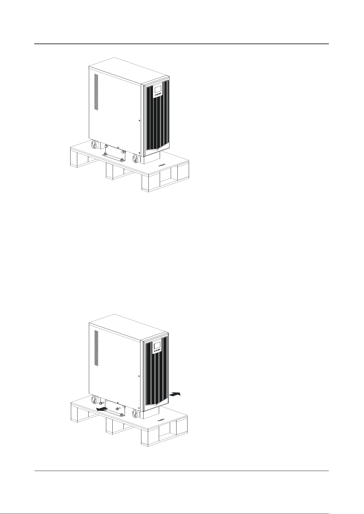
Step 4 Remove the package and take out the optional components and user manual. The appearance after
unpacking is as shown in Figure3-1.
20
Page 24
User Manual
3 Installation
igure3-1 Appearance after unpacking
F
Step 5 Check the device completeness.
Inspect the appearance of device for shipping damage, if any shipping damage is found, report it
to the carrier immediately.
Check if the types of the accessories are complete and correct. If there is any discrepancy, tak
not
es and contact the distributor immediately.
e
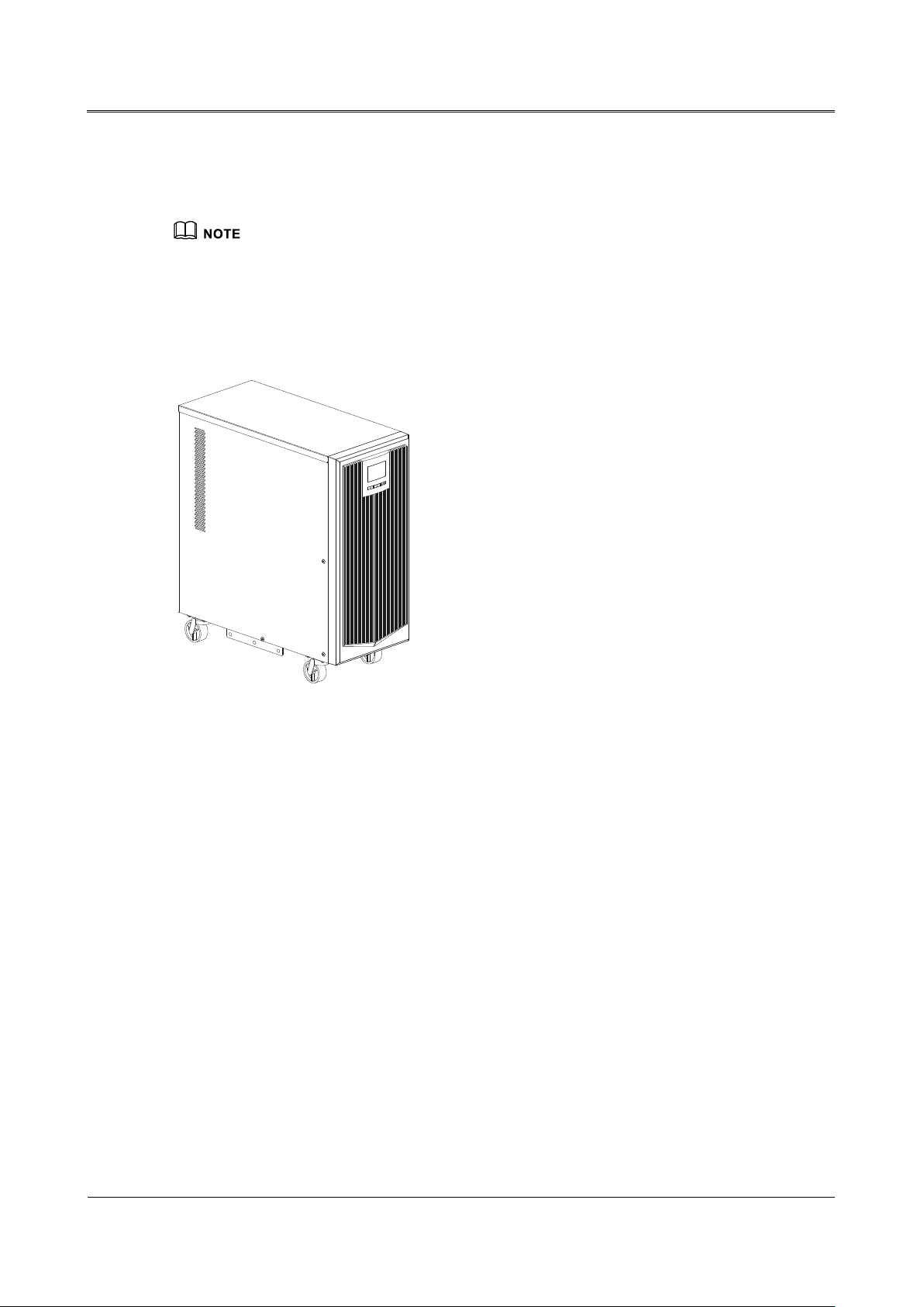
Step 6 If UPS is OK, dismantle four hexagonal bolts M8×20(two pieces on the left and right side
respectively) between the anchor frame and anchor support plate, as shown in Figure3-2.
Figure3-2 Dismantle the hexagonal bolts
21
Page 25
3 Installation
User Manual
Step 7 Move UPS to floor and fasten it.
After putting UPS in the floor , you can move it by f our Omni-dir ecti onal wheels at the bottom of UPS.
When moving UPS, the Omni-directional wheels should be at ON position. After moving UPS, the
Omni-directional wheels should be at OFF position to avoid UPS moving.
For stability concern, after moving UPS to the installation place. It's recommend to dismantle the
anchor frame in the wooden bracket and install it in the anchor support plate by four bolts M8*20. If
there has installation holes in the floor or other bases, fasten UPS in the floor or other bases
through anchor.
igure3-3 Install UPS in t he installation position
F
----End
3.2 Installation Preparation
3.2.1 Input Breaker Selection
Add a breaker(It's recommended that the breaker is with backfeed protection and bipolar
disconnection function) or a power distribution box in the input wire of UPS, which matches with the
power of UPS, to isolate the mains. Consider the charging power of UPS and the transient current
impact when power on, the current of the selected breaker should be 1.5~2 times of the max. input
current of UPS. Besides, the selected breaker should be without the power leakage protection to
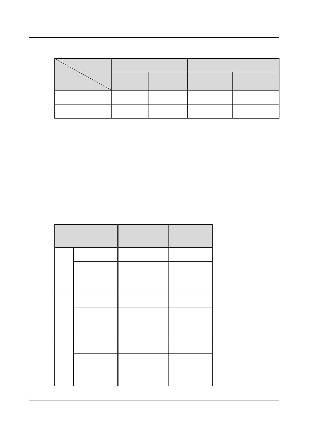
avoid mis-operation. The distribution box is better to be made by the professional company. The
selection of input breaker refers to Table3-1.
22
Page 26
User Manual
3 Installation
Table3-1 The recommended input breaker of (6-10kVA) UPS
(Neutral/live)
(Neutral/live)
Index
Model
6kVA (L) 36 50 39 50
10kVA/10KVA(S) 60 100 65 100
AC input (A) DC input (long backup model) (A)
Max. current Breaker Max. current Breaker
3.2.2 Selection of the Cross-sectional Area of Wire
For the selection of the cross-sectional area of AC input wire, AC output wire and battery wire of
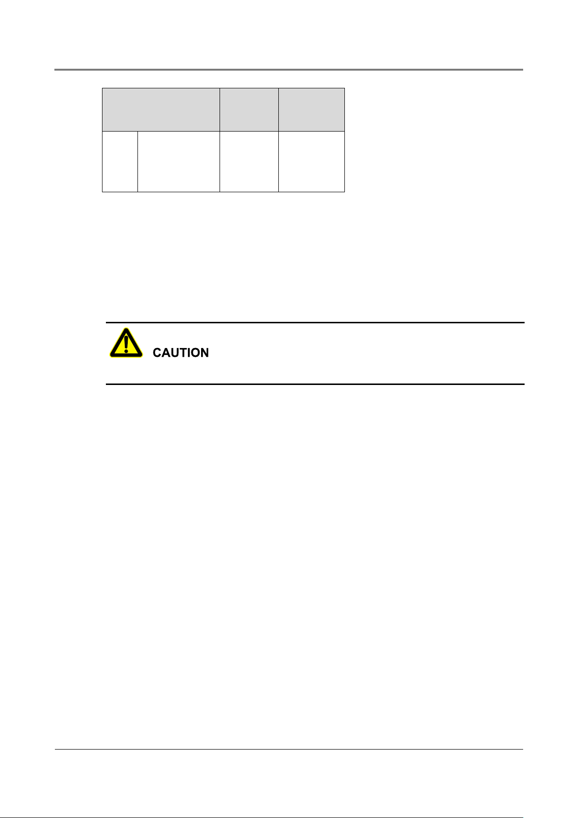
6kVA (L), 10kVA, 10kVA(S), please refer to Table3-2 for the corresponding recommended value and
choose upwards.
Table3-2 The ampacity of the recommended cross-sectional area of wire
KR6000(L)
Rated current(A) 30.2 48.5
AC input
Cross-sectional
area of wire
(mm2)
Rated current(A) 27.3 45.5
AC output
Cross-sectional
area of wire
(mm2)
DC input(Long
backup model)
Rated current(A) 30.6 52.0
Cross-sectional
6 10
6 10
KR(/B)1110
/KR1110S
area of wire
(mm2)
6 10
23
Page 27
3 Installation
User Manual
KR6000(L)
KR(/B)1110
/KR1110S
Ground
Cross-sectional
area of wire
(mm2)
3.3 Electrical Connection
Before performing the electrical connection, ensure all breakers in the rear panel of UPS, external
mains upstream switch, external battery upstream switch are all disconnected. It's prohibited to
perform wring when power on.
Place wires in such a way that no one can step on or trip over them.
3.3.1 1kVA(L)
10
In the 1kVA(L) series UPS, the input and output adopt sockets. When using it, please connect one
end of the input power wire with input socket and then connect the other end of the input power wire
with mains socket. Besides, connect the load power wire with the output socket. The wiring for the
input and output of the 1kVA(L) series UPS is as shown in Figure3-4.
24
Page 28
User Manual
3 Installation
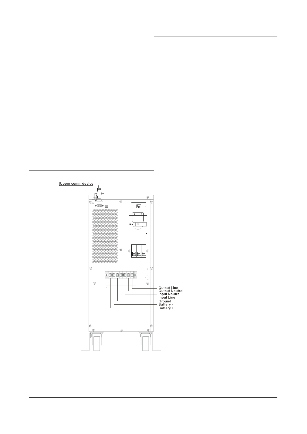
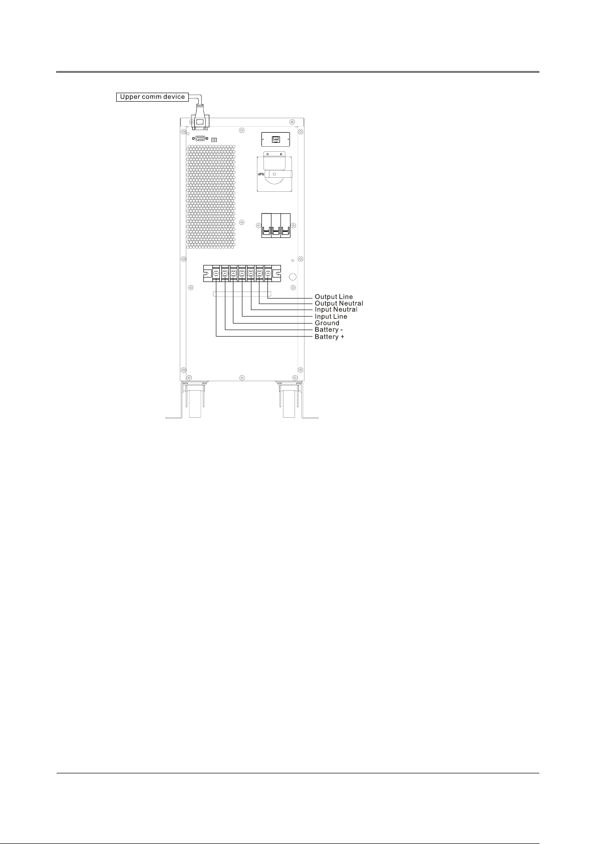
3.3.3 6kVA/6kVA(L)
In the 6kVA(L) series UPS, the input, output and battery adopt the terminal bar. The wiring for the
6kVA series UPS is as shown in Figure3-6 and the wiring for the 6kVA (L) series UPS is as shown in
Figure3-7.
Figure3-6 Wiring diagram of 6kVA
27
Page 29
3 Installation
User Manual
Figure3-7 Wiring diagram of 6kVA(L)
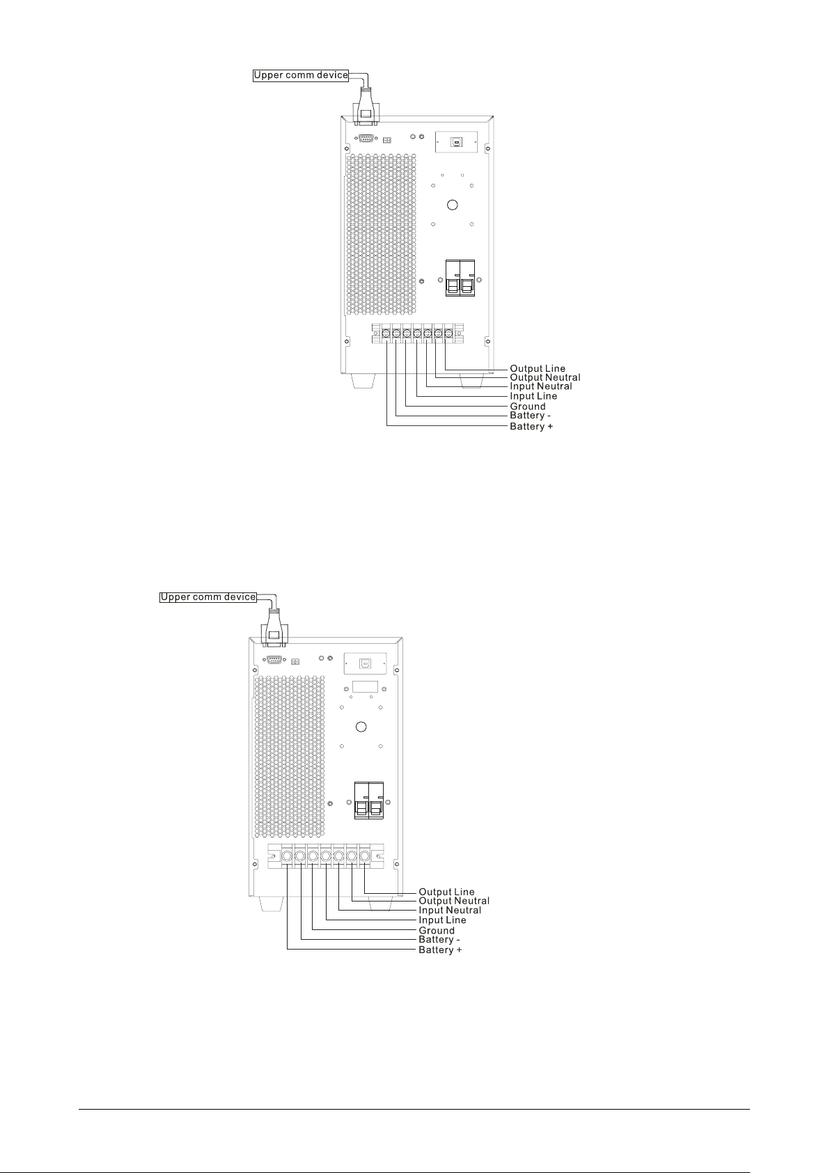
3.3.4 10kVA/10kVA(S)/10kVA(/B)
10kVA
In the 10kVA series UPS, the input, output and battery adopt the terminal bar. The wiring for the
10kVA series UPS is as shown in Figure3-8.
Figure3-8 Wiring diagram of 10kVA
10kVA(S)
In the 10kVA(S) series UPS, the input, output and battery adopt the terminal bar. The wiring for the
10kVA(S) series UPS is as shown in Figure3-9.
28
Page 30
User Manual
3 Installation
gure3-9 Wiring diagram of 10kVA (S)
Fi
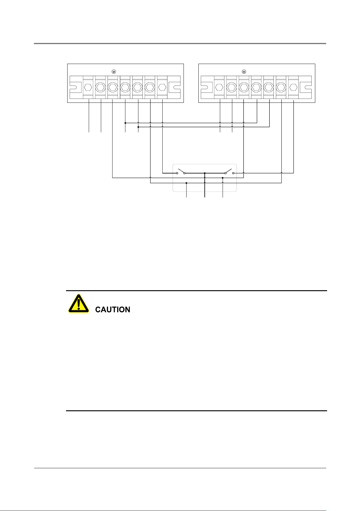
10kVA(/B)
Step 1 Install the battery and UPS of each UPS respectively according to the above description.
Step 2 Connect the AC output of each UPS with the output distribution box, as shown in Figure3-10.
29
Page 31
3 Installation
User Manual
Batt.+
UPS1(L)
UPS2(L)
N L GND
I
n
p
u
t
L
i
n
e
G
r
o
u
n
d
I
n
p
u
t
N
e
u
t
r
a
l
O
u
t
p
u
t
N
e
u
t
r
a
l
O
u
t
p
u
t
L
i
n
e
UPS1 UPS2
Batt. - Input L
Input N Output N
Output L Batt. +
Batt. -
Input L
Input N
Output N Output L
B
a
t
t
e
r
y
+
Output distribution box
B
a
t
t
e
r
y
-
B
a
t
t
e
r
y
+
B
a
t
t
e
r
y
-
G
r
o
u
n
d
O
u
t
p
u
t
L
i
n
e
O
u
t
p
u
t
N
e
u
t
r
a
l
I
n
p
u
t
L
i
v
e
I
n
p
u
t
N
e
u
t
r
a
l
O
u
t
p
u
t
N
e
u
t
r
a
l
O
u
t
p
u
t
L
i
n
e
G
r
o
u
n
d
igure3-10 Wiring diagram of 10kVA(/B) parallel system
F
Step 3 Connect the equipped parallel wires with parallel port i n the rear panel of each UPS in the p arallel
system.
1. The wiring method and phase sequence of the input of each UPS in the parallel system should be
the same. Besides, the bypass power of parallel system should be the in-phase.
2. Each UPS in the parallel system is connected to an independent battery pack. It's prohibited that
two UPS use the same battery pack.
3. Connect the equipped parallel wires with parallel port in the rear panel of each UPS in the parallel
system. Two RJ45 parallel ports are the same, that will have redundancy to improve reliability. If
there has a parallel port disconnected, UPS will have an alarm. After connecting the parallel wires,
fasten them in the rear panel holes of each UPS by cable ties.
30
----End
Page 32
User Manual
3 Installation
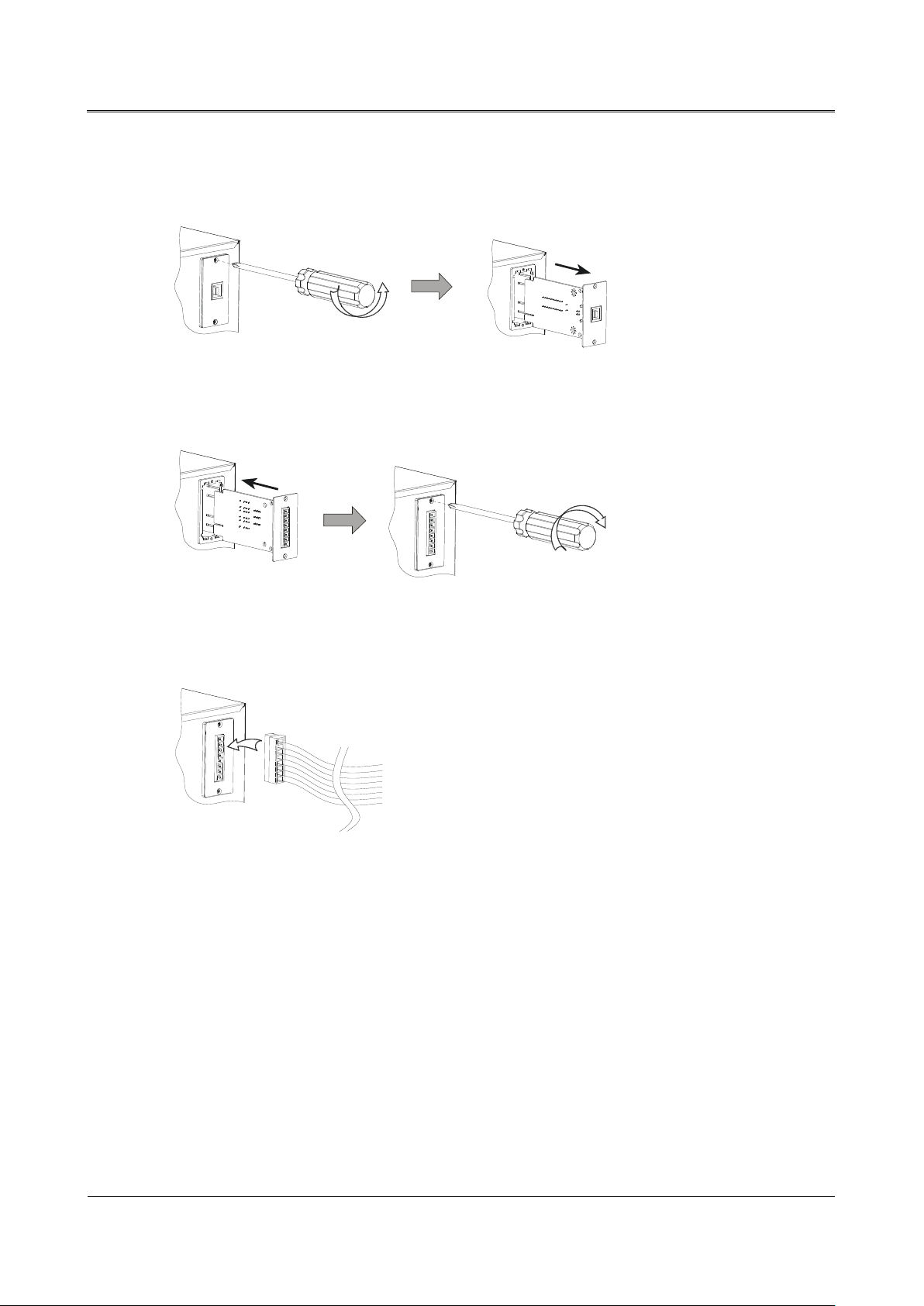
3.3.5 Intelligent Slot Installation
Step 1 Dismantle standard intelligent slot.
Figure3-11 Dismantle standard intelligent slot
Step 2 Install optional intelligent slot and fix it.
igure3-12 Install optional intelligent slot
F
Step 3 Connect communication cable.
igure3-13 Connect communication cable
F
----End
31
Page 33

4 Operation and Maintenance
User Manual
4 Operation and Maintenance
This chapter mainly describes the operation process, operation method, daily maintenance and
troubleshooting, etc.
4.1 Check Before Startup
Check if the wire connection is firm and the color of AC wires is in accordance with the
pecification.
s
Check if UPS is grounded reliably.
Check if the voltage between the neutral wire and grounding wire is less than 5Vac.
If installing the remote monitoring device in the UPS, check if the wiring in the RS232 port is
correct.
If it is long backup model, check if the wiring between UPS and battery cabinet is correct and
reliable.
Check if the wiring is neat and the wire binding is in accordance with the specification.
Check if the installation and wiring are good for transformation, expansion and maintenance i
f
uture.
Check that there is no short-circuit in the output of UPS and the load capacity isn't beyond the
rated capacity of UPS.
n
32
Page 34
User Manual
4 Operation and Maintenance
----End
4.2.2 6kVA(L)/ 10kVA(/B) /10kVA(S)
Step 1 Switch on the mains breaker, bypass breaker and battery breaker.
Step 2 Press "ON" button on the panel for 1s to start UPS.
Step 3 About 10s later, if the UPS works steadily, start loads, such as PC, etc.
Start load with the sequence that "high power device→small power device", which is to avoid
overload protection when starting high power device.
----End
4.3.2 6kVA (L)/10kVA (/B) /10kVA(S)
Step 1 Close load and keep UPS running without load for about10min to exhaust heat.
Step 2 Press "OFF" button on the panel for 1s.
Step 3 Switch off the battery breaker, bypass breaker and mains breaker.
----End
33
Page 35

4 Operation and Maintenance
User Manual
4.4 Parallel System Operation
4.4.1 Start Parallel System
Don't start loads until parallel system have started completely. Ensure all breakers in the distribution
box are switched off.
Start the parallel system following the procedures as below:
Step 1 After installing parallel system correctly, start each UPS in the parallel system according to 4.2
Startup Operation successively.
Step 2 When each UPS outputs, measure the inverting voltage of each UPS. The voltage difference between
the max. voltage and the min. voltage should be less than 5V. Switch on breakers that connected with
each UPS in th e distribution box in 5min and check the circulation current of each UPS that should
be less than 3A.
If the voltage difference is more than 5V, check if the output of each UPS are all 220V. If the volta ge
difference is more than 10V, please contact your local distributor or service center for help. Besides,
if the circulation current of each UPS is too large, it will damage inverter. If the circulation current of
each UPS is more than 3A, please contact your local distributor or service center for help.
Step 3 Switch on major output breaker and output breakers of each branch in the distribution box. Then start
load successively.
----End
4.4.2 Close Parallel System
Generally, it is not recommended that turn on or turn off the parallel system frequently.
Step 1 Close all loads;
Step 2 Press "OFF" button in the panel of each UPS to shut down UPS successively.
Step 3 Switch off breakers in the rear panel of each UPS.(In the daily operation, it's unnecessary to switch
them off).
----End
34
Page 36
User Manual
4 Operation and Maintenance
4.4.3 Remove Faulty UPS from Parallel System
Switch off breaker in the
distribution box , which connects
with the faulty UPS
.
Close the faulty UPS
according to shutdown
procedures.
Finish installing the
added UPS
Start the added UPS
according to the startup
procedures successively
Switch on breaker that
connected with added UPS in
the distribution box
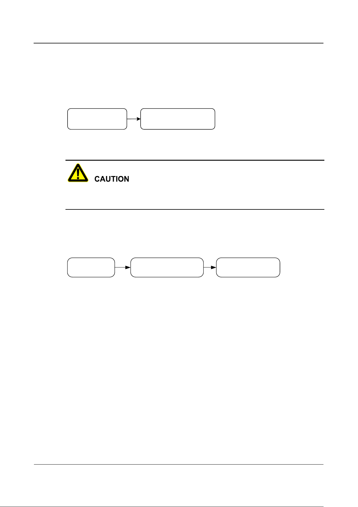
When one UPS failure, it will remove from parallel system automaticall y with sound&light alarm.
Now, perform the operations shown in Figure4-1 to remove the faulty UPS from parallel system
completely to achieve online hot maintenance or replacement.
F
igure4-1 Remove faulty UPS from parallel system
When the parallel system works normally, don't remove UPS from the parallel system until it's
switched off, or the power system will work abnormally.
4.4.4 Add New UPS into Parallel System
When it has to add one or more UPS into parallel system, perform the operations shown in Figure4-2.
When the added UPS works steadily, it will add into parallel system automatically for share current.
igure4-2 Add new UPS into parallel system
F
4.4.5 Redundancy Funciton of Parallel System
When adopting the N+1 redundancy backup design, the total output load should be less than N times
of rated load of single UPS. If there has a faulty UPS, it will remove form parallel system
automatically, which doesn't influence system running and enhances system reliability. When the
output load is more than N times of rated load of single UPS, the overload unit (more than N/(N+1)
times of rated load of single UPS)will have an alarm. e.g. For the parallel system with two UPS,
when the load of UPS is more than 50%, it will have overload alarm.
4.5 Periodic Preventative Maintenance
To improve the efficiency and reliability of UPS, perform the following maintenance regularly.
Clean UPS regularly by dry cloth. Don't use liquid or spray cleaner. Before cleaning, shut dow
PS.
U
n
35
Page 37

4 Operation and Maintenance
User Manual
Check if the wiring in the input and output are firmly and connect well.
Check the working status of cooling fans regularly. Prevent sundries from blocking the air outlet
f any damage, please replace it in time.
I
Check the battery voltage and the working status of UPS regularly.
4.6 Battery Maintenance
The working life of battery is based on environment temperature and discharge times. Using battery
in the high temperature for a long time or discharging battery deeply will reduce the working life of
battery.
Charge battery for ten hours before using it. During charging, it can use the battery. If the battery
and charger are powered off at the same time, the discharging time will be less than the standard
value.
Generally, charge and discharge battery once every four to six months. Discharge battery till the
battery is under-voltage and power it off and then charge it. In the high temperature area, charg
nd discharge battery once every two months. The charging time for the standard battery shoul
a
more than ten hours every time.
be
.
e
d
If UPS hasn't been used for a long time, it is recommended to charge battery more than ten hours
every three months.
Generally, the working life of battery is three to five years. If battery failure, replace it early. Th
ba
ttery replacement should be performed by authorized professional.
4.7 Maintenance Byass Mode(Only for UPS with Maintenance
Bypass)
When it n eeds to maintain UPS or replace battery, but it can't stop supplying power for load, switch
off UPS and transfer to bypass mode, dismantle the maintenance bypass cover and transfer the
maintenance bypass switch from maintenance bypass to bypass and then switch off mains breaker
and bypass breaker in the rear panel of UPS. Now, AC power draws through maintenance bypass
switch to supply power for load.
e
36
Page 38

User Manual
4 Operation and Maintenance
In the maintenance bypass mode, the re still exists elec tricity in the inpu t terminals, output te rminals,
on, UPS works in the bypass mode
is beyond the rated power of UPS. It should reduce
and the terminals in the filter board.
4.8 Troubleshooting
As shown in Table4-1, it only includes some common fault diagnosis. If any doubt, contact the local
office or distributor for details.
Table4-1 Troubleshooting
Fault phenomenon Possible reason
The mains is normal. When starting
UPS, it outputs normally. But it
works in the battery mode and the
buzzer beeps intermittently.
1) Check if the contacts and sockets in the input are with
poor contact;
2) Check if the input voltage amplitude or frequency o
m
ains displayed in the LCD is beyond the allowable
input range of UPS;
3) Check if the over-current protector in the rear panel is
f
After finishing installing UPS,
connecting with power will fuse the
fuse or cause power cut.
When starting UPS, the LCD display
and output are normal. But when
connecting with load, it will stop
outputting immediately.
Buzzer long beeps, fault indicator is
sprung. If yes, press the over-current protector switch.
Output short circuit or wiring for three phase of output
error.
1) UPS is overload seriously or the output circuit is
short-circuit. It should reduce load to the proper
capacity or find the short-circuit reason. The comm
eason is that the output changeover socket is
r
short-circuit or the input is short-circuit after UPS
failure.
2) It doesn't follow the startup sequence that "high power
device → small power device" to start load. Restart
UPS. When UPS works steadily, start high power
device first, and start small power device successively.
1) The output is overload. The load is too heavy, which
on
37
Page 39

4 Operation and Maintenance
User Manual
Fault phenomenon Possible reason
Fault info.
UPS has emergency protection(if equipped with
EPO function), Bypass output and inverting
There has busbar voltage fault in the UPS, the
temperature protection, the
Rapid beep (Alarm
going to protect. Please check if cooling fan
and inverter failure. load or select UPS with larger power capacity. It is
normal that UPS works in the bypass mode
temporarily for load startup impact and then recover
automatically
2) UPS over-temperature protection. Check if the air
inlet and air outlet of UPS is blocked or the worki
emperature of UPS is beyond the allowable range.
t
Usually, UPS works normally. When
UPS powers off, it doesn't transfer to
battery mode or it transfers to battery
mode and battery has under-voltage
protection soon.
1) Battery aging, battery capacity loss or it needs to
replace battery.
2) Battery charger fault. Usually, it can't charge battery.
3) Battery wire doesn't connect well or the terminals ar
wit
h poor contact.
When the load is PC, everything
The grounding is unreliable for the floating voltage
works normally. When power failure,
between the neutral wire and the grounding wire is too
UPS works normally, but the
high.
computer halts.
Table4-2 The m eaning of fault symbol and buzzer status
Fault symbol Buzzer status Meaning
ng
e
EPO Long beep
BUS Long beep
page (page up
or page down
by "SELECT"
TMP Long beep
button)
FAN
38
output are all closed.
inverting output is closed.
UPS has overinverting output is closed. Please check if cooling
fan damage and air vents blocked.
Fan fault alarm prompting, the inverting output is
once about every 0.2s)
damage.
Page 40

User Manual
4 Operation and Maintenance
Fault symbol Buzzer status Meaning
Fan fault protection. The inverting output is
check if output is
in the parallel system. Please
check if the inverting voltage format or the
Rapid beep (Alarm
check if the cooling fan in the charging
circuit protection in the
Slow beep (Alarm
In the mains mode, bypass voltage or bypass
frequency abnormal. Please check if the bypass
Slow beep (Alarm
CAN communication abnormal in the parallel
paralleled wire is
damaged or only a UPS in the parallel system
Load energy bars all
Rapid beep (Alarm
Output overload alarm. the output is going to
Slow beep (Alarm
Battery voltage is too high. Please check if
Battery energy bars
Rapid beep (Alarm
Battery is about to run out. Please pay attention
Long beep
closed.
Output fault, please
OUT Long beep
short-circuit or the load is too large.
Battery fault, battery voltage too low or too high
BAT Long beep
protection.
Parameters error
PRA Long beep
parallel mode setting(PRA mode and SGL mode)
is different.
PRL Long beep Parallel wire in the parallel system disconnected.
PWR Long beep Power failure. If it is abnormal, repair it in time.
1. Charger over-temperature protection(Please
CHG
BYP
CAN
flicker
Battery energy bar all
flicker
once about every 0.2s)
once about every 2.0s)
once about every 2.0s)
once about every 0.2s)
once about every 2.0s)
board failure);
2. Output shortcharger.
breaker is switched on.
system. Please check if
powers on.
close, please reduce load.
battery or charger failure.
39
Page 41

4 Operation and Maintenance
User Manual
Fault symbol Buzzer status Meaning
are all off and the
once about every 0.2s) to protect device and save you data in the PC.
frame flickers
The above information is for user to know some common fault diagnosis when UPS failure. If it may be
inner components failure, please contact the professional.
40
Page 42

User Manual
5 Package, Transportation, Storage
5 Package, Transportation, Storage
5.1 Package
The package of product is carton. When packing, pay attention to the placing direction requirements.
One side of carton, it should print warning icons, including keep dry, handle with care, up, stacking
layer limit, etc. The other side of carton, it should print the device model, etc. Print device name on
the front of carton.
5.2 Transportation
Pay attention to warnings on the carton. Don't impact it severely when transportation. In case of
damaging device, it should follow the placing direction that shows on the carton. Don't carry device
with the objects that inflammable, explosive, or corrosive. Don't put device in the open-air warehouse
when transhipment. Leaching and mechanical damage by rain, snow or liquid objects is prohibited.
5.3 Storage
When storing device, it should follow the placing direction that shows on the carton. The gap is 20cm
between the carton and ground and the clearance is at least 50cm from carton to wall, heat source,
cold source, windows or air inlet.
The storage environment temperature is 0℃~40℃ and the relative humidity is 20%~80%. In
warehouse, It's prohibited that there has poisonous gas, objects that inflammable and explosive,
corrosive chemical objects. Besides, it shouldn't have too strong mechanical shaking, impact and
strong magnetic field. Under the storage conditions above, the storage period is six months. If it is
beyond six months, it has to recheck. When long term storage ,it should charge battery every three
months.
41
Page 43

Appendix A Technical Specifications
User Manual
A.2 6kVA(L)/10kVA(/B) /10kVA(S)
, the load capacity decreases linearly
overload for
High overload
Model
6kVA 6kVA(L) 10kVA(S) 10kVA(/B)
Index
When the voltage range is 176Vac~
Input features
Voltage range(V)
Frequency range (Hz) 50/60±10%(50/60 self-adaption)
Input method Single phase three wire
Battery voltage (V)
Power capacity
(VA/W)
Voltage (V) 220±2%(default)(208/220/230/240 settable)
Frequency (Hz) 50/60±0.2%( battery mode)
Wave Sine-wave
Voltage distortion THD<1%(linear load); THD<4%(non-linear load)
the voltage range is 80Vac~176Vac
according to the input voltage amplitude.
192(default)(16~20 cell*12V settable)
6000/5400 10000/9000
275Vac, UPS can be with full load. When
Output features
Power factor
Transfer time (ms) 0
Low overload
for 1
0min(for
1min above
Overload ability
30℃)
Medium
30s
for 500ms
0.9 (If the environment temperature is lower than 30℃, it can set it to 1.0)
6300VA/5670W <
Load≤7800VA/7020W
7800VA/7020W <
Load≤9000VA/8100W
Load>9000VA/8100W Load>15000VA/13500W
10500VA/9450W <
Load≤13000VA/11700W
13000VA/11700W <
Load≤15000VA/13500W
44
Page 44

User Manual
Appendix A Technical Specifications
Index
Mechanical part
According to
external battery
According to
external battery
, the charge recovery time is determined by the capacity of
Working temperature
Model
6kVA 6kVA(L) 10kVA(S) 10kVA(/B)
Dimensions(W×D×H)
230×502×553 190×422×337 230×502×553 190×422×337
(mm)
Weight(kg)
54.5 10.9 56.2 12.5
5~20min(full
1~15min(full
Backup time
load/ half load)
pack.
load/ half load)
pack.
For standard model, the charge recovery time is less than 10 hour. For long
Charge recovery time
backup model
external battery pack.
Communication
Other features
RS232 port supports UPS power management software.
interface
Display LCD displays the running status of UPS.
Alarm function Battery low-voltage, mains abnormal, UPS failure, output overload
Protection function
Battery under-voltage protection, overload protection, short-circuit protection,
over-temperature protection, input over-voltage protection
Noise (dB) <55
-5 ~ 40
(℃)
Relative humidity 0 ~ 95%, non-condensation
Specifications are subject to change without prior notice.
45
Page 45

Appendix B Acronyms and Abbreviations
UPS KR Series(1-10kVA) UPS
User Manual
Appendix B Acronyms and Abbreviations
A
AC Alternating Current
D
DC
Direct Current
E
E
CO Energy Control Operation
EPO Emergency Power Off
L
L
CD Liquid Crystal Display
R
R
S232 Recommend Standard232
S
NMP Simple Network Management Protocol
S
U
PS Uninterruptible Power System
U
46
 Loading...