

Enerpac ZW3 Series, ZW4 Series, ZW5 Series Instruction Sheet
Instruction Sheet
POWERFUL SOLUTIONS. GLOBAL FORCE.
L3075 Rev. A 04/14
Index:
English:. . . . . . . . . . . . . . . . . . . . . . . . . . . . . . . . . . . 1-14
Français:. . . . . . . . . . . . . . . . . . . . . . . . . . . . . . . . . 15-28
Español: . . . . . . . . . . . . . . . . . . . . . . . . . . . . . . . . . 29-42
Portuguese: . . . . . . . . . . . . . . . . . . . . . . . . . . . . . . 43-56
Repair Parts Sheets for this product are available from the Enerpac
web site at www.enerpac.com, or from your nearest Authorized
Enerpac Service Center or Enerpac Sales office.
1.0 IMPORTANT RECEIVING INSTRUCTIONS
Visually inspect all components for shipping damage. Shipping
damage is not covered by warranty. If shipping damage is found,
notify carrier at once. The carrier is responsible for all repair and
replacement costs resulting from damage in shipment.
SAFETY FIRST
2.0 SAFETY ISSUES
Read all instructions, warnings and cautions
carefully. Follow all safety precautions to
avoid personal injury or property damage
during system operation. Enerpac cannot be responsible for
damage or injury resulting from unsafe product use, lack of
maintenance or incorrect product and/or system operation.
Contact Enerpac when in doubt as to the safety precautions and
operations. If you have never been trained on high-pressure
hydraulic safety, consult your distribution or service center for a
free Enerpac Hydraulic safety course.
Failure to comply with the following cautions and warnings could
cause equipment damage and personal injury.
A CAUTION is used to indicate correct operating or maintenance
procedures and practices to prevent damage to, or destruction of
equipment or other property.
A WARNING indicates a potential danger that requires correct
procedures or practices to avoid personal injury.
A DANGER is only used when your action or lack of action may
cause serious injury or even death.
WARNING: Wear proper personal protective gear when
operating hydraulic equipment.
WARNING: Stay clear of loads supported by hydraulics.
A cylinder, when used as a load lifting device, should
never be used as a load holding device. After the load has
been raised or lowered, it must always be blocked mechanically.
DANGER: To avoid personal injury keep hands and
feet away from cylinder and workpiece during
operation.
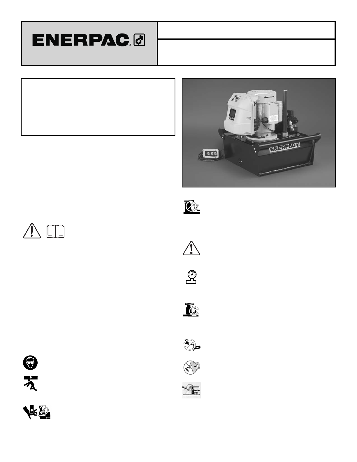
Pallet Coupling Pumps
Series ZW3, ZW4 and ZW5
WARNING: Do not exceed equipment ratings. Never
attempt to lift a load weighing more than the capacity of
the cylinder. Overloading causes equipment failure and
possible personal injury. The cylinders are designed for a max.
pressure of 350 bar [5,000 psi]. Do not connect a jack or cylinder
to a pump with a higher pressure rating.
DANGER: Never set the relief valve to a higher pressure
than the maximum rated pressure of the pump. Higher
settings may result in equipment damage and/or personal
injury. Do not remove relief valve.
WARNING: The system operating pressure must not
exceed the pressure rating of the lowest rated component
monitor operating pressure. It is your window to what is happening
in the system.
Sharp bends and kinks will internally damage the hose leading to
premature hose failure.
materials and packings. For optimum performance do not expose
equipment to temperatures of 65 °C [150 °F] or higher. Protect
hoses and cylinders from weld spatter.
in the system. Install pressure gauges in the system to
CAUTION: Avoid damaging hydraulic hose. Avoid sharp
bends and kinks when routing hydraulic hoses. Using a
bent or kinked hose will cause severe back-pressure.
Do not drop heavy objects on hose. A sharp impact may
cause internal damage to hose wire strands. Applying
®
pressure to a damaged hose may cause it to rupture.
IMPORTANT: Do not lift hydraulic equipment by the
hoses or swivel couplers. Use the carrying handle or other
means of safe transport.
CAUTION: Keep hydraulic equipment away from
flames and heat. Excessive heat will soften packings and
seals, resulting in fluid leaks. Heat also weakens hose
DANGER: Do not handle pressurized hoses. Escaping
oil under pressure can penetrate the skin, causing serious
injury. If oil is injected under the skin, see a doctor
immediately.
WARNING: Only use hydraulic cylinders in a coupled
system. Never use a cylinder with unconnected couplers.
If the cylinder becomes extremely overloaded, components
can fail catastrophically causing severe personal injury.
IMPORTANT: Hydraulic equipment must only be serviced
by a qualified hydraulic technician. For repair service,
contact the Authorized ENERPAC Service Center in your
area. To protect your warranty, use only ENERPAC oil.
WARNING: Immediately replace worn or damaged parts
with genuine ENERPAC parts. Standard grade parts will
break causing personal injury and property damage.
ENERPAC parts are designed to fit properly and withstand high
loads.
WARNING: Do not use electric pumps in an explosive
atmosphere. Adhere to all local and national electrical
codes. A qualified electrician must do installation and
modification.
FLOW CHARTS
WARNING: Start the pump with the valve in the neutral
position to prevent accidental cylinder operation. Keep
hands clear of moving parts and pressurized hoses.
WARNING: These pumps have internal factory adjusted
relief valves, which must not be repaired or adjusted
except by an Authorized Enerpac Service Center.
CAUTION: To prevent damage to pump electric motor,
check specifications. Use of incorrect power source will
damage the motor.
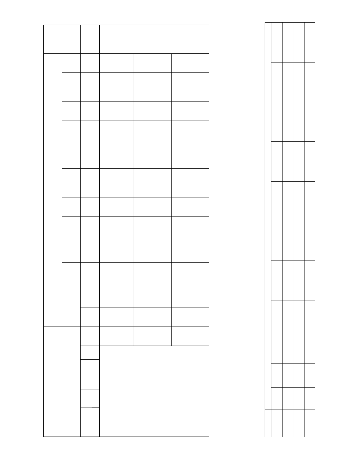
3.0 SPECIFICATIONS
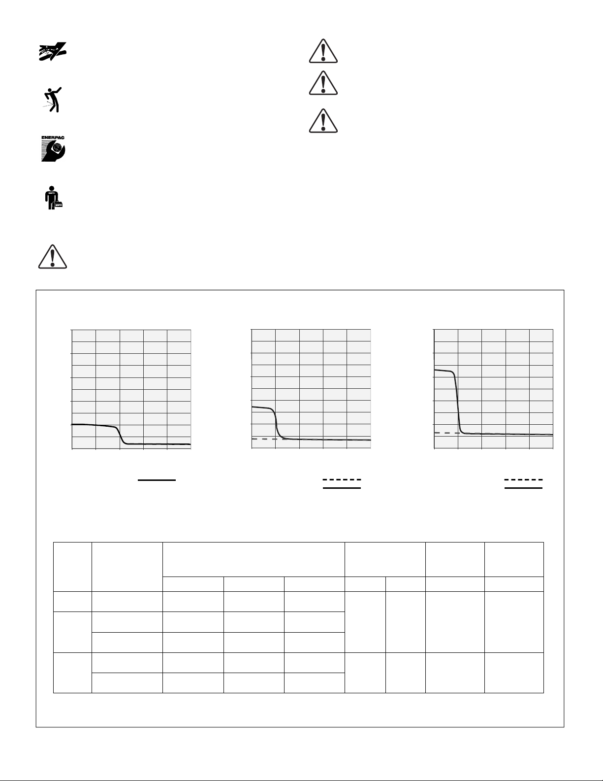
3.1 Flow Charts (see Figure 1)
3.2 Performance Charts (see Figure 1)
3.3 Electric Current Draw
(Refer to Table 4 in Section 8.0 of this manual)
ZW3 Series
1000
900
800
/min)
3
700
600
500
Oil Flow (in
400
300
200
100
0
0 1,000 2,000 3,000 4,000 5,000
1000
900
800
/min)
3
700
600
500
Oil Flow (in
400
300
200
100
0
0 1,000 2,000 3,000 4,000 5,000
Pressure (psi)
ZW3 series two-stage
ZW4 series single-stage
ZW4 series two-stage
PERFORMANCE CHART
Pump
Series
Operation Output Flow Rate
(in3/min)
100 psi 700 psi 5,000 psi hp RPM (psi) (dBA)
ZW3 Two-stage 202 190 40
ZW4 Series
Pressure (psi)
1000
900
800
/min)
3
700
600
500
Oil Flow (in
400
300
200
100
0
0 1,000 2,000 3,000 4,000 5,000
ZW5 series single-stage
ZW5 series two-stage
Motor Size Relief Valve
Adjustment
Range
ZW5 Series
Pressure (psi)
Sound
Level
Single-stage 64 63 60
ZW4
Two-stage 350 305 60
Single-stage 128 126 120
ZW5
Two-stage 650 602 120
Output flow rate is listed at 60 Hz.
Flow rate will be approximately 5/6 of these values at 50Hz.
Figure 1, Pump Specifications
1.0 1750 1,000 - 5,000 75
1.5 1750 1,000 - 5,000 75
2

B
A
B
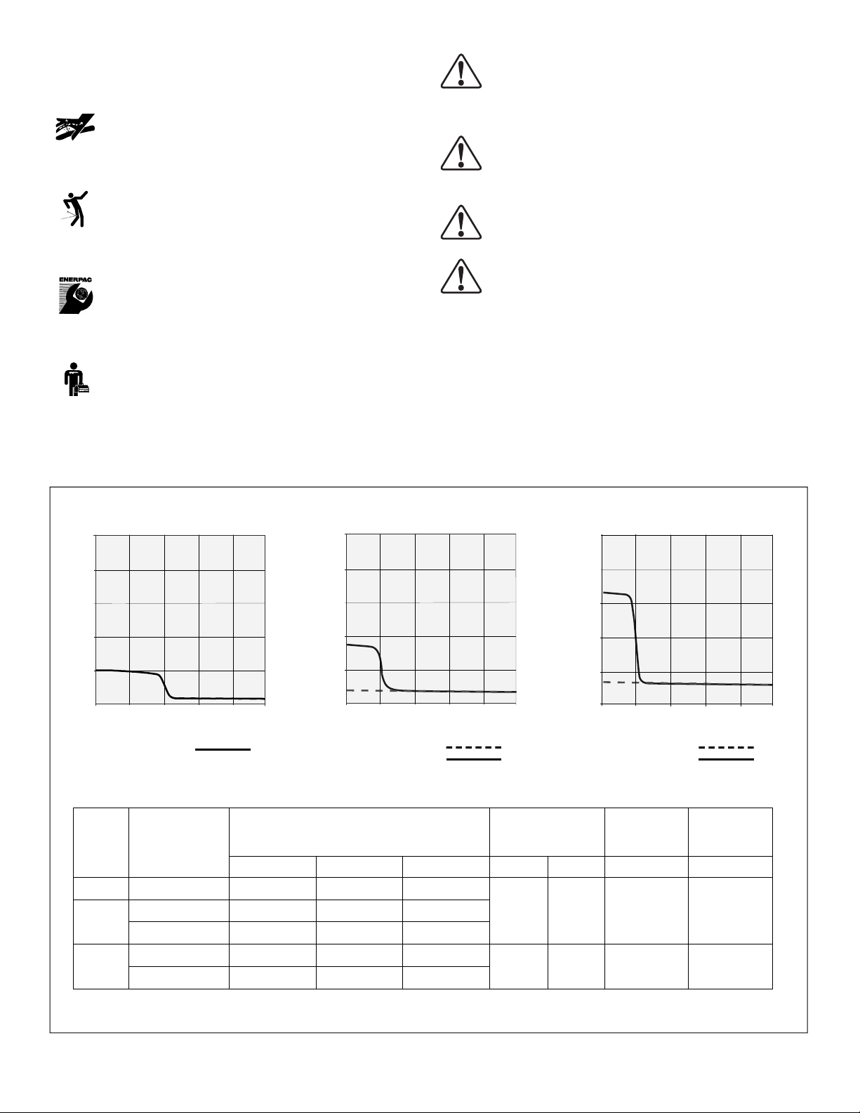
Figure 2, ZW Breather Cap Installation
C
D
4.0 INSTALLATION
Install or position the pump to ensure that air flow around the
motor and pump is unobstructed. Keep the motor clean to
ensure maximum cooling during operation.
4.1 Reservoir Breather Cap (See Figure 2)
For shipping purposes, a shipping plug (A) is installed in the
breather port on the top of the reservoir. Before using replace
the shipping plug (A) with the breather cap (B).
Note: The oil fill port uses a SAE #10 plug (C). It is mounted at
the top of the fill pipe extension (D).
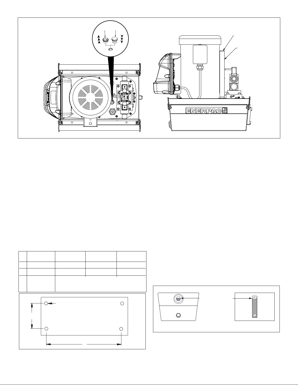
4.2 Pump Mounting
Refer to Figure 3 for mounting dimensions to secure the pump
to a fixed surface.
1-2 Gal. (4-8 L)
in. (mm)
A 3.75 (95) 11.0 (279) 15.6 (396) 18.9 (480)
B 9.00 (229) 12.0 (305) 12.0 (305) 12.0 (305)
tapped holes,
C
M8 x 1.25
2.5 Gal. (10 L)
in. (mm)
Ø 0.34 (8.6) diameter through holes
0.25 (6)
(Note: Reservoir viewed from below)
5 Gal. (20 L)
in. (mm)
deep
10 Gal. (40 L)
in. (mm)
4.3 Electrical Connections
THE PUMP IS FACTORY EQUIPPED WITH THE COMMON
ELECTRICAL PLUG FOR A GIVEN VOLTAGE, ALTERING
THE PLUG TYPE SHOULD ONLY BE DONE BY A QUALIFIED
ELECTRICIAN, ADHERING TO ALL APPLICABLE LOCAL AND
NATIONAL CODES.
1. The disconnect and line circuit protection to be provided by
customer. Line circuit protection to be 115% of motor full load
current at maximum pressure of application
2. For additional information, refer to pump name plate for power
rating. Also refer to Table 4 in Section 8.0 for motor current draw
information.
4.4 Oil Level
Check the pump oil level prior to start-up. If oil level is low,
remove the SAE #10 plug from the fill pipe extension and add oil
as needed (see Figure 1).
The reservoir is full when the oil level is as shown in Figure 4.
Tank is full
when oil level
is here.
10 to 40 liter4 and 8 liter
C
IMPORTANT: Add oil only when all system components are fully
A
B
Figure 3
retracted, or the system will contain more oil than the reservoir
can hold.
3
Figure 4
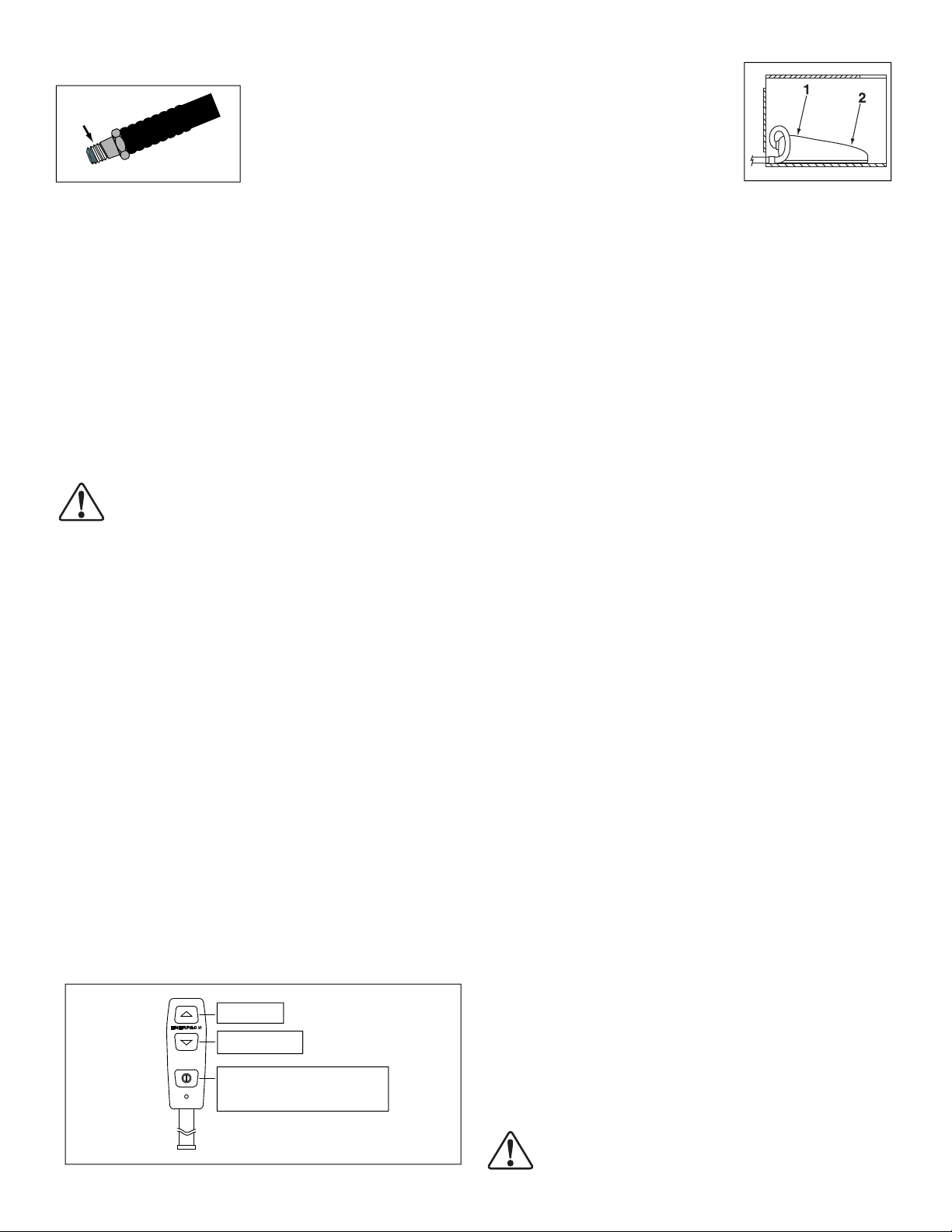
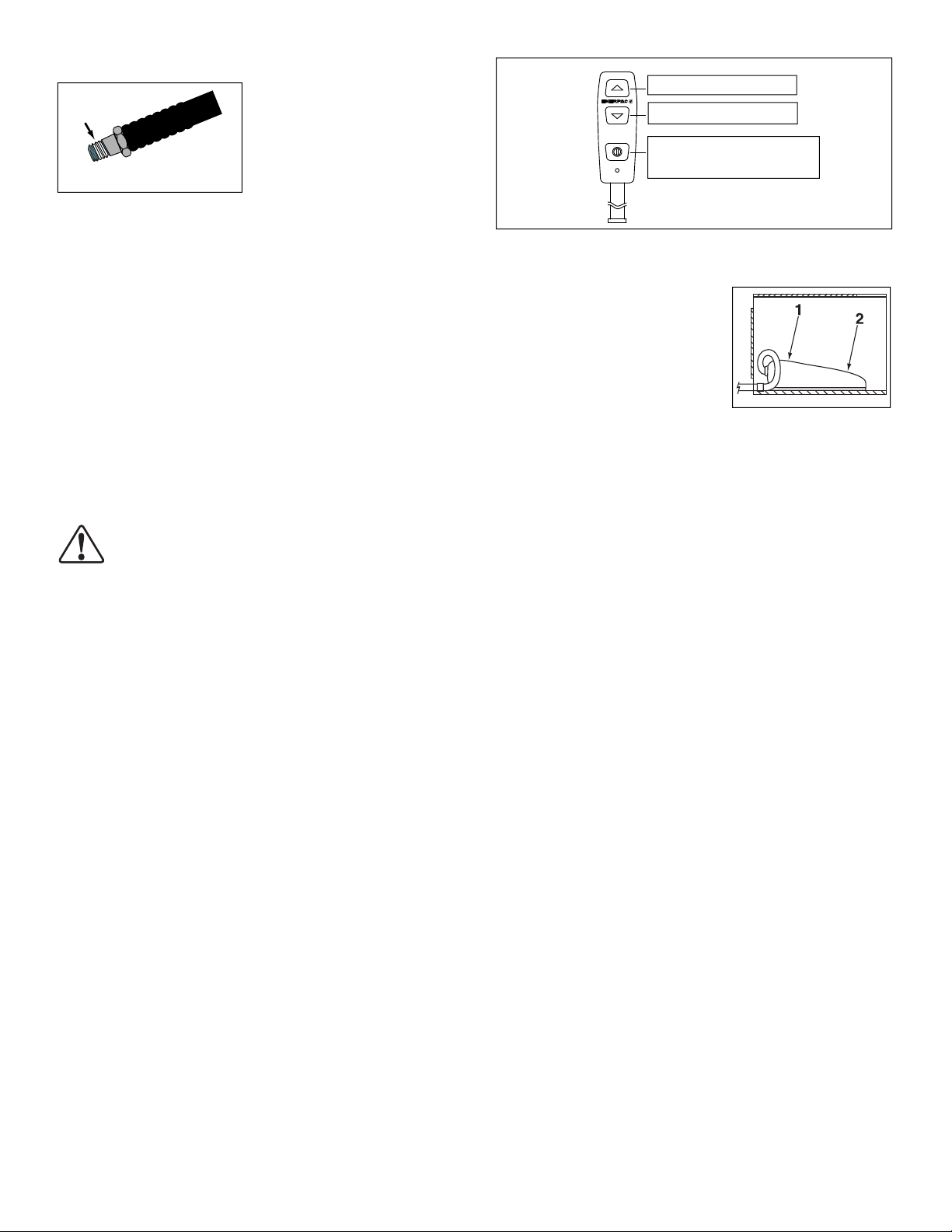
4.5 Hydraulic Connections
Figure 5
Apply 1-1⁄2 wraps of Teflon tape
or other suitable sealant to the
hydraulic hose fitting, leaving the
first complete thread free of tape
or sealant as shown in Figure 5.
5.2 Foot Switch Option
(see Figure 7)
1. Motor On - Momentary Clamp
2. Motor On - Momentary Unclamp
Shroud On/Off = Not Used
(disabled)
Figure 7
Thread hose(s) into outlet port(s) of the valve (see valve body for
port identification).
Connect the clamp (extend) hose to valve port “A”.
Connect the unclamp (retract) hose to valve port “B”.
If desired, a pressure gauge may be installed in valve port “GA”
or “GB”.
Note: “GA” measures “A” port pressure, “GB” measures “B” port
pressure, “GP” measures pump pressure down stream of system
check. The pump pressure transducer is factory installed in the
“GP” port and must remain installed in this location to ensure
proper pump operation.
5.0 OPERATION
WARNING: Review sections 5.1-5.4 and 6.1-6.4 before
starting pump. Be sure that Dwell Mode operation and
functions are clearly understood before connecting unit
to power.
1. Check the oil level of pump and add oil if necessary.
2. Make sure the shipping plug has been removed and the
breather cap is installed. (See Section 4.1)
3. Connect unit to power. Wait until “READY” is displayed
before pressing any button on shroud or pendant. Note:
During the boot sequence, the microcontroller identifies any
button operation as a potential malfunction and prevents the
motor from starting. Reset by disconnecting power for 30
seconds.
4. For an overview of pump operation, including pendant
functions, refer to sections 5.1-5.4. For detailed LCD control
panel operation instructions, see sections 6.1-6.4.
5.1 Pendant Operation (see Figure 6)
Oil flow and motor operation are controlled by the pendant
buttons. The pump will run and the cylinder will clamp when the
pendant Up-Arrow button is pressed. The pump will run and the
cylinder will unclamp when the pendant Down-Arrow button is
pressed. Releasing either button at any time will stop the pump
and will relieve pressure in the hoses (see Fig. 6).
1. Up Arrow = Motor On - Momentary Clamp
2. Down Arrow = Motor On - Momentary Unclamp
3. On/Off = Not Used (disabled)
Shroud On/Off = Not Used (disabled)
Up Arrow
®
Down Arrow
ON / OFF
(disabled - not functional)
Figure 6
5.3 Automatic Dwell Mode Operation
The Dwell Mode feature allows the pump to react automatically at
two user-defined pressure values, “PRESR A” and “PRESR B”.
This feature can be turned on and off as desired. See the
following paragraphs for additional information. Also refer
to Section 6.2 for detailed Dwell Mode operation and setting
instructions.
1. Dwell Mode Off
The pump LCD control panel will display pressure as a
simple pressure gauge. No additional actions will be performed
regardless of PRESR A and PRESR B values.
2. Dwell Mode On
The pump will automatically de-energize the motor and valve
solenoid after the specified PRESR A or PRESR B value is
reached AND the specified dwell time (in seconds) has elapsed.
When the pump stops, pressure in hoses will drop to zero (0) so
that couplers can be disconnected from the pallet.
Note: “AUTO” is shown on the LCD screen when Dwell Mode is
turned-on. “READY” is shown when Dwell Mode is turned-off.
5.3.1 Overview of Dwell Mode
Before the PRESR A or PRESR B value is reached:
• Pendant Up-Arrow and Down-Arrow buttons will function
as described in Section 5.1.
After the PRESR A or PRESR B value is reached:
• Continuing to press and hold the Up or Down Arrow
button after the specified pressure value is reached will
activate the dwell timer. The LCD screen backlight will
begin flashing, and the pump will continue running until
the user-defined dwell time (1 to 60 seconds) has elapsed.
• To ensure proper clamping and unclamping, the Up or
Down Arrow button must remain depressed until the pump
stops.
• Releasing the Up or Down Arrow button will stop the
automatic cycle, and the LCD screen backlight will stop
flashing.
• If dwell time is set to zero (0), the pump will stop
immediately when the specified pressure value (PRESR A
or PRESR B) is reached.
Restarting the Automatic Cycle:
Releasing and depressing the pendant Up-Arrow or Down-
Arrow button will restart the automatic cycle.
IMPORTANT:
relief valve pressure setting. When Dwell Mode is ON and pendant
Up or Down Arrow button is depressed, pressure will continue to
rise to the relief valve setting even after the specified pressure value
(PRESR A or PRESR B)
when using Dwell Mode, be certain that the PRESR A and PRESR B
values are set at least 200 psi [13,7 bar] BELOW the relief valve
pressure setting.
4
Maximum system pressure is determined by the
is reached. To ensure proper operation
WARNING: Set pump to “DWELL OFF” and disconnect
electrical power to pump before working on pump or
hydraulic system.

5.4 Relief Valve Adjustment
The pump is equipped with a user-adjustable relief valve. Adjust
pressure as follows:
1. Set the pump to DWELL OFF. Refer to Section 6.2 for
instructions.
2. Install a 0-6,000 psi [0-400 bar] gauge in the “A” port (see
figure 8). Place a 3/8" pipe plug in the “B” port and torque to
25 ft-lbs [33 Nm].
3. Loosen the relief valve locknut to permit adjustment of set
screw.
4. Press and hold the Up-Arrow button on the pendant. (see
figure 6). Allow pressure to build.
5. To increase pressure: SLOWLY turn the relief valve set
screw clockwise until pressure increases to the desired
setting.
6. To decrease pressure:
a. Turn the relief valve set screw counter-clockwise
b. Press and hold the Up-Arrow button on the pendant.
(see figure 6). Allow pressure to build.
c. SLOWLY turn the relief valve set screw clockwise until
pressure increases to the desired setting.
7. When the desired pressure setting is reached, lock the set
screw with the locknut. DO NOT overtighten.
8. Release the Up-Arrow button. Check that gauge indicates
zero (0) psi.
Relief valve body
(DO NOT TURN)
Port “B” Port “A”
B
Set screw
Figure 8
A
Locknut
one turn.
6.0 OPERATION AND USE INSTRUCTIONS -
LCD CONTROL PANEL
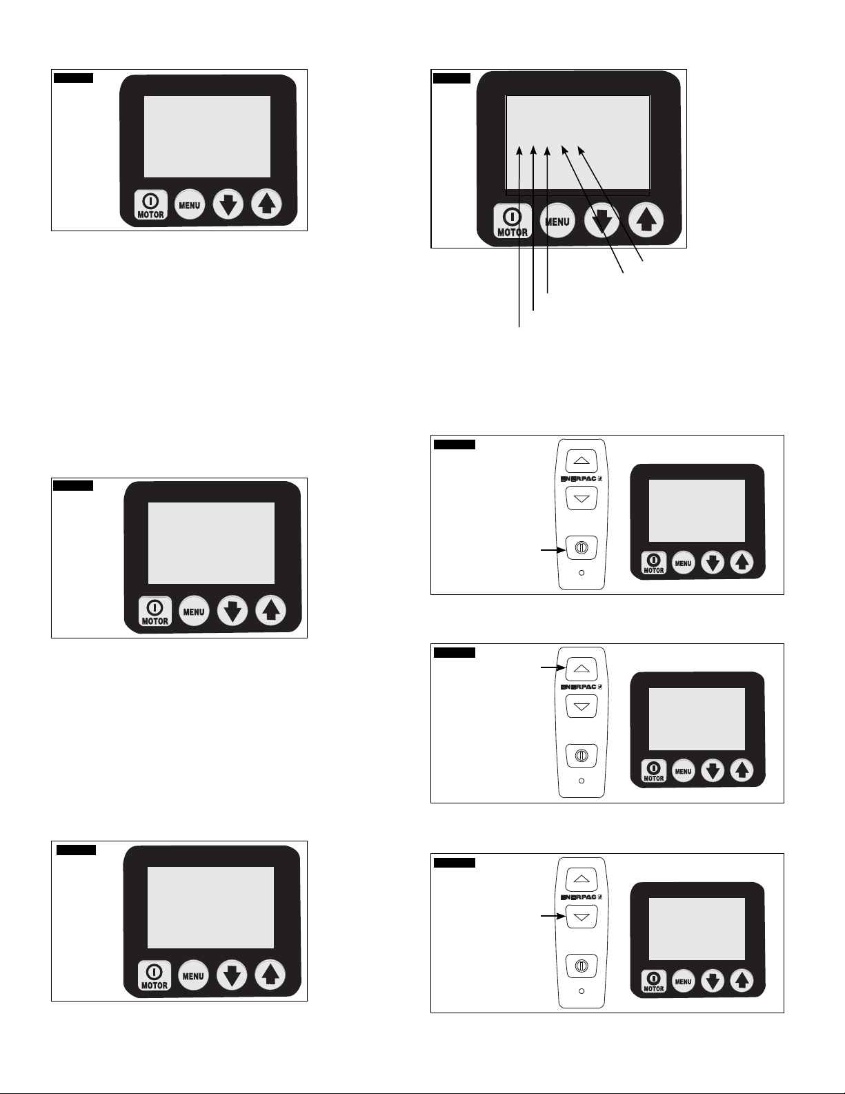
6.1 LCD Function
Screen 1
Number
display
SET
00000000
0000.0
HOURS CYCLES
LOW MOTOR
VOLTAGE OVERLOAD
(See Screen 1) The LCD control panel is the main interface
between the operator and the pump. By using the button
switches on the panel, the menus and functions described in the
following sections of this manual can be activated.
The backlighted LCD screen provides real time system pressure
readings. Pump fault and warning conditions are also displayed
on the screen as required.
Text display
PSI MPa
BAR
CAUTION: Make sure that the plastic overlay, that
protects the LCD screen and the button switches, is not
broken or otherwise damaged. Never punch the button
switches with a sharp or pointed instrument, use fingertips only.
Clean the overlay regularly with a damp cloth; never use
aggressive or abrasive detergents.
A. Boot Sequence
When the pump is connected to electrical power the LCD
screen will show: “FIRMWARE” 7.x for 1 second, then “Model
9” for 0.5 seconds, and then “Motor 1P/3P” for 0.5 seconds.
Additional information may appear depending on model and
installed accessories.
This is setup information about your pump that may be needed
for service. The boot sequence is finished successfully when the
text display on the LCD screen shows “READY” (sequence takes
approximately 2 seconds).
The pump microcontroller will automatically recognize the
transducer, and the current pump pressure (typically “0” psi/bar
at startup) will be shown on the LCD screen.
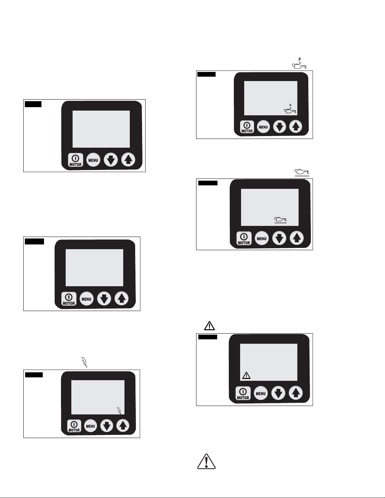
B. LCD Operational Buttons
The LCD control panel is equipped with four button switches:
On/Off / Menu / Down Arrow / Up Arrow
• The pump motor On/Off button is not functional for this
pump model. The pump will NOT start or stop when the
On/Off button is pressed. Motor operation is controlled by
depressing and releasing the Up-Arrow and Down-Arrow
buttons on the pendant (remote mode) or on the LCD control
panel (local mode).
• The Menu button enables the operator to step from normal
operational mode into menus. With repeated pressing the
operator steps through the various menus. Pressing the
Menu button also saves any changes made. To return to the
normal operational mode, press and hold the Menu button
for two seconds or don’t push any button for 60 seconds.
• The Down-Arrow and Up-Arrow buttons serve two purposes.
When the LCD screen shows one of the menus, the DownArrow and Up-Arrow buttons are used to step through the
menu’s options. When the pump is placed in Local Mode
(see Section 6.2
operate the B and A electric solenoids and the motor. The
pendant is non-operational in local mode.
L), the Down-Arrow and Up-Arrow buttons
C. Menus Available
The software provides the operator with a series of available
menus.
• Normal Operation – Default start-up screen. Appears
immediately after power is connected and microcontroller
has booted.
• Units – Set the pressure units to PSI / BAR / MPa, with psi
being the default setting.
• Dwell ON-OFF – Turn the Dwell Mode ON or OFF.
The additional Dwell Mode menus DWELL A, DWELL B,
PRESR A and PRESR B can be selected only when Dwell
Mode is ON.
• Motor – display the motor hour meter and on/off cycle
counter (nonresettable)
• Low Volt – display the low voltage hour-meter (nonresettable)
• Advance – display the Advance solenoid hour meter and on/
off cycle counter (nonresettable)
5

• Retract – display the Retract solenoid hour meter and on/off
cycle-counter (nonresettable)
• Local – set the pump local mode on/off
• Language – set the language of the display to English /
Spanish / French / Italian / German / Portuguese, with
English being the default setting
• Diagnose – display to show input signals from the pendant
and other electrical accessories
6.2 LCD Menus
Note: For additional information about each menu, also refer to
Table 2, Quick Reference Chart (QRC), located in Section 8.0 of
this manual.
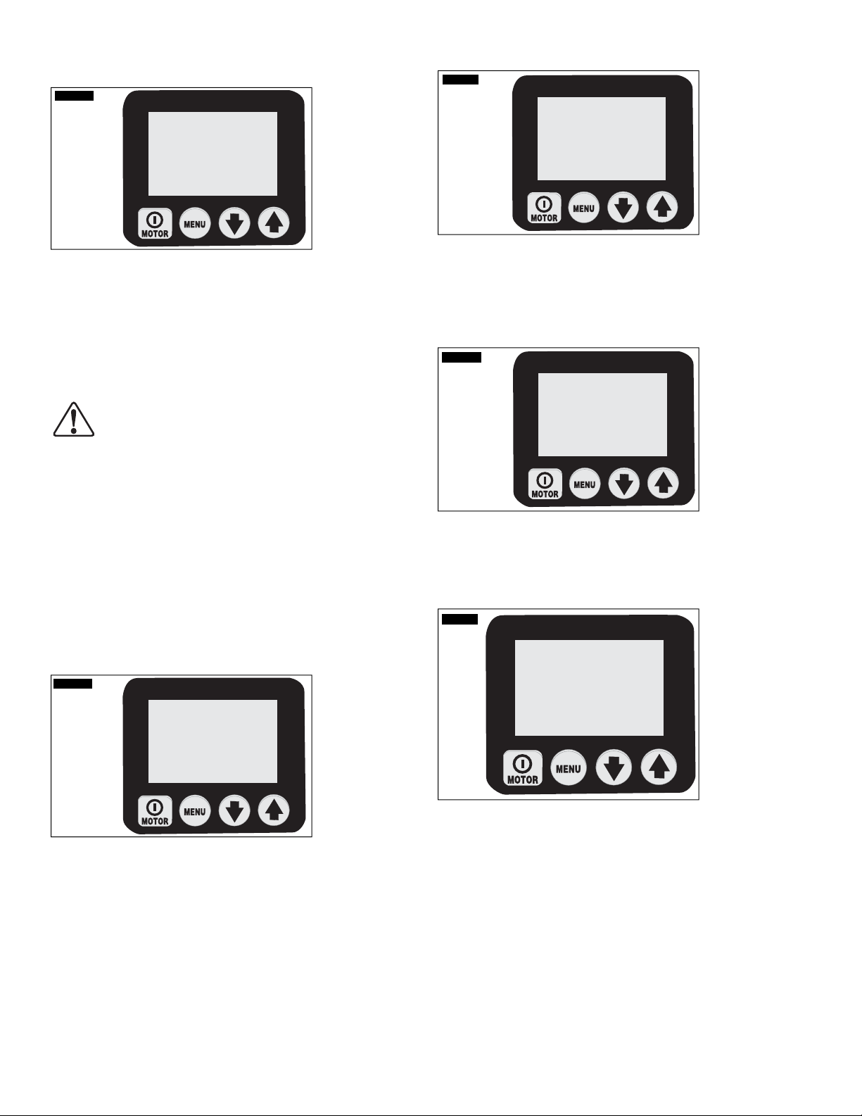
A. Normal Operation “READY” Screen
Screen 22
Pump operation is as follows:
DWELL OFF – The motor will continue to run and the electric
valve will remain shifted until the Up or Down Arrow button on the
pendant is released (no automatic operation).
DWELL ON – the pump will automatically shut-off the motor
and de-energize the electric valve when the hydraulic pressure
reaches the operator-defined pressure limit (PRESR A or B) AND
the operator defined dwell time (DWELL A or B) has elapsed.
IMPORTANT: For automatic shut-off to occur, the pendant Up or
Down Arrow button must remain depressed (held down) until the
dwell time has completely elapsed.
D. “PRESR A” Menu
(accessible only when Dwell Mode is ON)
Screen 5
READY
0
(See Screen 2.) The READY screen indicates that the
microcontroller has booted successfully. Enter into the menus
by pressing the Menu button. See QRC step 1.
B. “UNITS” Menu
Screen 33
SET
(See Screen 3.) This screen allows the operator to set the unit
of pressure-measurement by pressing the Down (Up) Arrow
buttons. PSI, BAR, Mpa are the options with PSI being the
default. Save setting and step forward by pressing the Menu
button. See QRC step 2.
C. “DWELL ON-OFF Menu
Screen 14Screen 4
SET
DWELL
PSI
UNITS
PSI MPa
BAR
ON
SET
PRESR A
5000
(See Screen 5.) This screen allows the operator to set the PRESR A limit
for the pump. After pressure reaches this limit, the DWELL A function
will be activated and the motor / electric valve will remain energized for
the specified number of seconds. The default pressure value is 5000 psi
[344 bar].
The PRESR A value is adjusted by pressing the Up-Arrow and DownArrow buttons.
Menu button. See QRC step 3b.
E. “DWELL A” Menu
(accessible only when Dwell Mode is ON)
Screen 6
(See Screen 6.) This screen allows the operator to set the DWELL A time
in seconds. After the specified DWELL A time (0 to 60 seconds) has
elapsed, the pump will de-energize the motor / electric valve.
The DWELL A value is adjusted by pressing the Up-Arrow and DownArrow buttons. If the DWELL A time is set to zero (0) seconds, the pump
will shut-off immediately when the PRESR A limit is reached.
Save setting and step forward by pressing the
SET
DWELL A
60
PSI
(See Screen 4.) This screen allows the operator to toggle the
pump’s Dwell Mode On and Off by pressing the Down (Up)
Arrow buttons. ON or OFF are the options. Dwell Mode must be
ON to allow the operator to set the pressure and dwell settings.
Save setting (ON or OFF) and step forward by pressing the Menu
button. See QRC step 3a.
Save setting and step forward by pressing the Menu button. See
QRC step 3b.
6
F. “PRESR B” Menu
(accessible only when Dwell Mode is ON)
Screen 7
SET
PRESR B
5000
(See Screen 7.) This screen allows the operator to set the PRESR B limit
for the pump. After pressure reaches this value, the Dwell Mode feature
will be activated and the motor / electric valve will remain energized for
the specified number of seconds. The default value is 5000 psi [344 bar].
The message “Use A” will appear first. Choosing this selection will set
the PRESR B limit to the same value as PRESR A. If desired, PRESR B
can be adjusted to a different setting by pressing the Up or Down Arrow
buttons again.
CAUTION: Due to motor coast down, valve shift time,
and system oil capacitance, always set the user
adjustable relief valve 200 psi above the higher of the
two pressure values (PRESR A or PRESR B) to prevent pressure
spikes. See Section 5.4 for relief valve adjustment instructions.
PSI
H. “Motor” Menu
Screen 94
MOTOR
4.8
HOURS CYCLES
(See Screen 9.) This screen allows the operator to read the
number of hours (On/Off cycles) the motor has been operated.
Toggle between hours and cycles by pushing either the Down
or Up Arrow button. Step forward by pressing the Menu button.
See QRC step 5.
I. “Low Volt” Menu
Screen 10
LOW VOLT
.0
HOURS CYCLES
IMPORTANT: When the Dwell timer is activated, the pump will
continue to build pressure to the system relief valve setting. The
relief valve setting should be adjusted to the maximum fixture
clamping pressure, to avoid over-pressurizing any components.
Note: Maximum system pressure is mechanically limited to
approximately 5,300-5,600 PSI [366-386 bar] by an internal relief
valve located within the pump element. Setting the PRESR A or
PRESR B pressure value higher than the relief valve maximum
limit will not result in higher system pressure.
G. “DWELL B” Menu
(accessible only when Dwell Mode is ON)
Screen 8
SET
DWELL B
60
(See Screen 8.) This screen allows the operator to set the DWELL B
time in seconds. After the specified DWELL B time (0 to 60 seconds)
has elapsed, the pump will de-energize the motor / electric valve.
(See Screen 10.) This screen allows the operator to read the
number of hours the pump has been operated in low-voltage
condition. Step forward by pressing the Menu button. See QRC
step 6.
J. “Advance” Menu
Screen 11
ADVANCE
188
HOURS CYCLES
(See Screen 11.) This screen allows the operator to read the
number of hours (On/Off cycles) the Advance solenoid has been
operated. Toggle between hours and cycles by pushing either the
Down or Up Arrow buttons. Step forward by pressing the Menu
button. See QRC step 7.
The DWELL B value is adjusted by pressing the Up-Arrow and DownArrow buttons. The message “Use A” will appear first. Choosing this
selection will set the DWELL B time to the same value as DWELL A. If
desired, DWELL B can be adjusted to a different setting by pressing the
Up or Down Arrow buttons again.
If the DWELL B time is set to zero (0) seconds, the pump will shut-off
immediately when the PRESR B limit is reached.
Save setting and step forward by pressing the Menu button. See
QRC step 3b.
7
K. “Retract” Menu
Screen 12
RETRACT
334
HOURS CYCLES
(See Screen 12.) This screen allows the operator to read the
number of hours (On/Off cycles) the Retract solenoid has been
operated. Toggle between hours and cycles by pushing either
the Down or Up Arrow button. Step forward by pressing the
Menu button. See QRC step 8.
_______________________________________________________
General note for all hour and cycle displays:
HOURS DISPLAYED
- up to 9999.9 the display will show decimal hours
- between 10,000 - 99,999 whole hours will be displayed (decimal “.” is not
displayed).
- over 99,999 hours the meter starts over at 0.0 reading decimal hours
CYCLES DISPLAYED
- over 99,999 cycles the meter starts over at 0
_________________________________________________________
L. “Local” Menu
Screen 13
SET
LOCAL
N. “Diagnose” Menu
Screen 15
SET
DIAGNOSE
00001
Pendant UP ARROW Button
Pendant ON/OFF Button
(See Screen 15.) This screen allows the operator to troubleshoot
several pendant problems by displaying if the microcontroller has
received a signal from the pendant button. No signal indicates the
problem is most likely with the pendant keypad or pendant cord.
Use Local mode to operate pump until problem can be corrected.
See QRC step 11.
Screen 16
PSI
(not used)
Fan
Pendant DOWN ARROW Button
DIAGNOSE
10001
PSI
OFF
(See Screen 13.) This screen allows the operator to toggle the Local
mode ON or OFF. With Local mode ON, the shroud buttons replace
the pendant buttons as the method to operate the pump (Note:
The word “Local” replaces “READY” on the “Normal Operations”
display and the pendant buttons become deactivated).
Local mode will provide operation of the pump if the pendant
or pendant cord is damaged. Toggle Local mode ON or OFF
by pressing the Down (Up) Arrow button. Save setting and step
forward by pressing the Menu button. See QRC step 9.
Local mode OFF is the default value. Local mode ON will revert
to Local mode OFF if power is disconnected.
M. “Language” Menu
Screen 14
SET
ENGLISH
Press
(See Screen 16.) Diagnose screen with Pendant motor button
pushed.
Screen 17
Press
DIAGNOSE
01001
PSI
(See Screen
pushed.
Screen 18
17
.) Diagnose screen with Pendant Advance button
Press
DIAGNOSE
00101
PSI
(See Screen 14.) With a language shown on the text display the
operator can change the display language by pressing the Down
(Up) Arrow buttons. Save setting and step forward by pressing the
Menu button. See QRC step 10.
(See Screen 18.) Diagnose screen with Pendant Retract button pushed.
8
6.3 Fault Conditions
Any fault will shut down and prevent pump from starting.
A. Clearing a Fault Condition from the LCD
After the fault causing problem has been corrected, clear the fault
message from the LCD by disconnecting electrical power from the
pump, wait until all characters clear the LCD (~ 30 seconds), then
reconnect power.
B. Power Failure
Display: “POWER OFF”
Screen 19
POWER
OFF
(See Screen 19.) The Power Off fault is displayed when the main
power supply drops to 65% or less of nominal voltage. The pump
will automatically shut off the valves and the motor, and display
“Power Off” on the LCD. Note: Power Off is also displayed for
several seconds after the unit is disconnected from electrical
power.)
C. Button Fault
Display: “Button Fault”
Screen 20
operator must clear the fault by disconnecting and reconnecting
electrical power as described in Section 6.3A.
E. Oil Temperature
(requires optional level/temperature switch)
Display: “OIL TEMP FAULT”
Screen 22
OIL TEMP
FAULT
(See Screen 22.) The Oil Temperature Fault is displayed when the
temperature of the oil inside the reservoir exceeds 175 ºF (80 °C).
F. Oil Level (requires optional level/temperature switch)
Display: “OIL LEVEL FAULT”
Screen 23
OIL LEVEL
FAULT
BUTTON
FAULT
(See Screen 20.) The Button Fault is displayed when the
microcontroller detects any button press during the boot sequence
or if shroud on/off button is held in for more than 3 seconds.
D. Motor Overload
Display: “MTR OVLD FAULT”
Motor Overload
Screen 21
MTR OVLD
FAULT
MOTOR
OVERLOAD
(See Screen 21.) The Motor Overload fault is displayed when the
electric current draw exceeds the pre-set limit of the pump’s
internal circuit breaker. The circuit breaker will automatically
reset in about 2 to 3 minutes after the condition has been
corrected. However, before the pump can be restarted, the
(See Screen 23.) The Oil Level Fault is displayed when the oil level
inside the reservoir drops below 1.3" (34 mm) from bottom.
6.4 Warning Conditions
All warnings notify operator of abnormal operating condition,
however, allow pump to continue operating. Warnings will
automatically clear once issue has been resolved.
A. Low Voltage
Display: “LOW VOLT”
Low Voltage
Screen 24
LOW VOLT
LOW
VOLTAGE
(See Screen 24.) A “Low Voltage” condition is defined as an
operating condition with the main power supply is at or below
80% of nominal voltage. While running the pump under this
condition, the “Low Voltage” signal will flash on the LCD and
the Low Voltage hours will be counted and stored by the pump
microcontroller. Normal pump operation is still provided.
CAUTION: For optimized pump performance it is
recommended NOT to run the pump during a Low
Voltage condition.
9

7.0 MAINTENANCE
Frequently inspect all system components for leaks or damage.
Repair or replace damaged components. Electrical components,
for example, the power-cord, may only be repaired or replaced by
a qualified electrician, adhering to all applicable local and national
codes.
7.1 Check Oil Level
Check the pump oil level prior to start-up. If oil level is low,
remove the SAE #10 plug from the fill pipe extension and add oil
as needed (see figures 2 and 4). Always be sure cylinders are fully
retracted before adding oil to the reservoir.
7.2 Change Oil and Clean Reservoir
Enerpac HF oil is a crisp blue color. Frequently check oil condition
for contamination by comparing pump oil to new Enerpac oil. As
a general rule, completely drain and clean the reservoir every 250
hours, or more frequently if used in dirty environments.
Note: This procedure requires that you remove the pump from
the reservoir. Work on a clean bench and dispose of used oil
according to local codes.
1. Remove the drain plug and drain all oil from the reservoir.
Clean and reinstall the drain plug.
2. Unscrew the 13 bolts holding the cover plate to the reservoir
and lift the pump unit out of the reservoir. Be careful not to
damage the filter screen.
3. Thoroughly clean the reservoir and reservoir magnet (if
equipped) with a suitable cleaning agent.
4. Remove the pick-up filter screen for cleaning. (Do not pull
on the screen or the bottom of the intake to avoid possible
damage.) Clean the screen with solvent and a soft brush.
Reinstall.
5. Reassemble the pump and reservoir, installing a new reservoir
gasket.
6. Fill the reservoir with clean Enerpac hydraulic oil. The
reservoir is full when oil level is as shown in Figure 4.
7.3 Changing the Filter Element (optional)
A return line filter may be ordered as an accessory to the pump.
The filter element should be replaced every 250 hours, or more
frequently in dirty environments. The filter manifold is equipped with
a 25 psi (1.7 bar) bypass to prevent over pressure rupture if filter
plugging occurs. Filter element replacement part number is PF25.
8.0 TROUBLESHOOTING AND ADDITIONAL
REFERENCE INFORMATION
Refer to the following tables as needed:
• Table 1 (page 11) contains the pump troubleshooting guide.
• Table 2 (pages 12-13) contains a quick reference chart (QRC)
that describes the operation of the LCD control panel.
• Table 3 (page 14) contains additional information about pump
automatic operation and functions.
• Table 4 (page 14) contains detailed pump electrical current
draw information.
IMPORTANT: Only qualified hydraulic technicians should service
the pump or system components. A system failure may or may
not be the result of a pump malfunction. To determine the cause
of the problem, the complete system must be included in any
diagnostic procedure.
Note: The troubleshooting guide included in Table 1 is provided
as an aid to help diagnose and correct various possible pump
malfunctions and is intended for use only by qualified hydraulic
service personnel. For repair service, contact your nearest
Authorized Enerpac Service Center.
10

Table 1, Troubleshooting Guide
Problem Possible Cause Action*
Pump will not start Fault condition See Section 5.0, Operation and 6.3, Fault Conditions for
details
Pendant does not function Pump in local mode
Pendant damage
Motor stops under load Low voltage See Sections 6.3B and 6.4A
Electric valve will not operate No power or wrong voltage
Solenoid cable disconnected or damaged
Valve out of adjustment
Pump fails to build pressure or
less than full pressure
Pump builds full pressure, but
load does not move
Cylinder drifts back on its own External system leak
Low oil level
Relief valve set too low
External system leak
Internal leak in pump
Internal leak in valve
Internal leak in system component
Load greater than cylinder capacity at full pressure
Flow to cylinder blocked
Internal leak in a system component
Non-load holding valve used
See Section 6.2L, Local Menu
See Section 6.2N, Diagnose Menu
See authorized service center
Turn off other electric loads
Use heavier gauge extension cord
Connect to correct power source per pump name plate
Connect, repair, or replace cable
See authorized service center
Add oil per Section 4.4
Adjust per Section 5.4
Inspect and repair or replace
See authorized service center
See authorized service center
See authorized service center
Reduce load or add cylinder capacity
Check hydraulic couplers for full engagement
Inspect all hydraulic connections and replace or repair
See authorized service center
See authorized service center
Single-acting cylinder will
not return
Double-acting cylinder will not
return
Pump runs hot Advance or retract flow restricted
Pump pressure goes above
“PRESR A” or “PRESR B” value
Dwell Mode does not work
correctly
After boot-up, LCD display
shows “P switch open”
LCD display shows “FILTER” Loose jumper on power board See authorized service center.
No load on a “load return” cylinder
Return flow restricted or blocked
Valve malfunction
Cylinder return spring broken
Return flow restricted or blocked
Valve malfunction
High ambient temperature
Cylinder comes to a sudden stop (i.e., strokes out) Set user adjustable relief valve 200 psi above “PRESR A”
Pressure transducer installed in pressure port other
than “GP”
Pressure switch circuit is open See authorized service center.
Add load
Check couplers for full engagement
See authorized service center
See authorized service center
Check couplers for full engagement
See authorized service center
Check couplers for full engagement
Install heat exchanger for hydraulic oil
or “PRESR B” value to redirect excess oil flow
Move pressure transducer to “GP”
* As required during troubleshooting, refer to sections 6.2 LCD Menus, 6.3 Fault Conditions and 6.4 Warning Conditions.
11
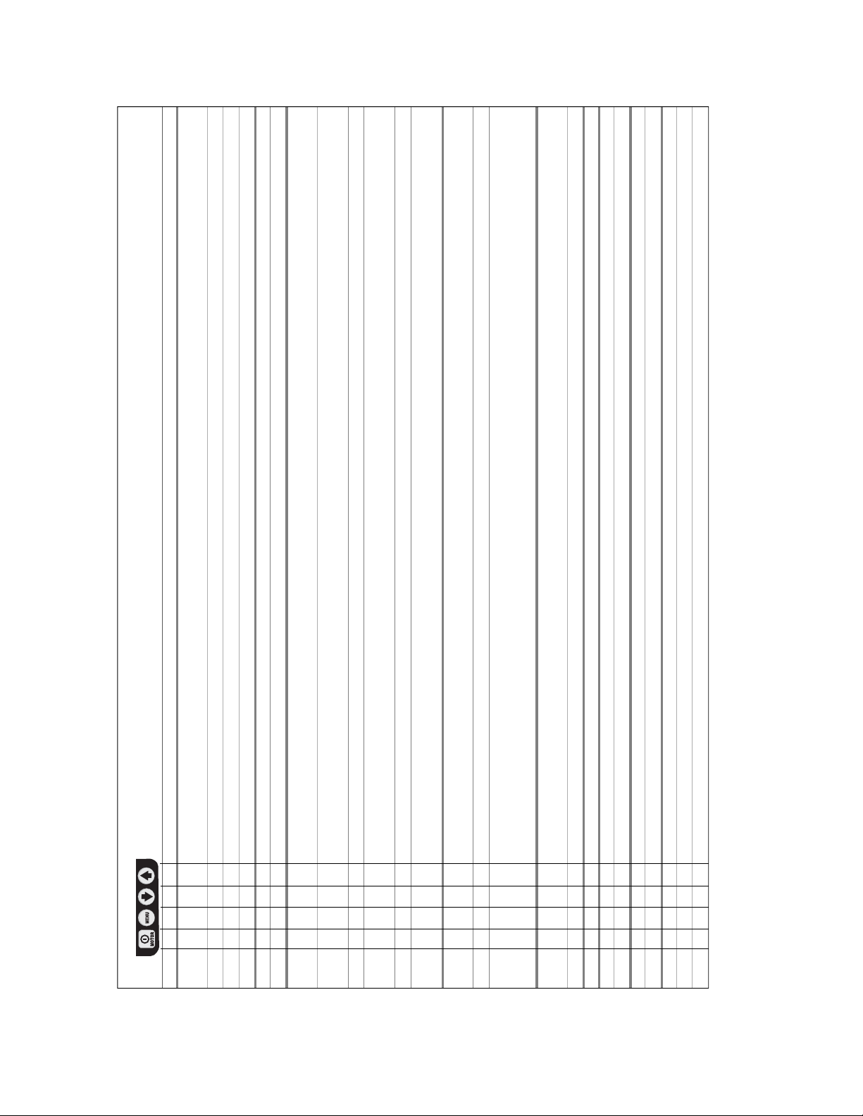
Table 2, Quick Reference Chart (QRC) • ZW Series Pallet Coupling Pumps • Firmware 7.x • Pump Program Number 9
Step Switch Text Expected reading / symbol / status Units Comments
I M t s display digital display
1 READY default reading “READY” after power on and boot sequence
2 X UNITS PSI save previous setting and step forward to select units,
default is psi
X “ BAR step through units using either the Up or
X “ MPA the Down Arrow button
X “ PSI
3a X DWELL OFF select dwell mode
X “ ON toggle between on and off by using the arrow buttons
3b X PRESR A value of “A” clamping pressure limit for Dwell Mode increase/decrease value by using the arrow-buttons
default value is 5000 PSI [344 bar]
X DWELL A value of “A” clamping dwell time for Dwell Mode increase/decrease value by using the arrow-buttons
default value is 0
X PRESR B USE A make PRESR B value same as PRESR A value
X PRESR B value of “B” clamping pressure limit for Dwell Mode increase/decrease value by using the arrow-buttons
(if USE A is not selected) default value is 0
X DWELL B USE A make DWELL B value same as DWELL A value
X DWELL B value of “B” clamping dwell time for Dwell Mode increase/decrease value by using the Arrow-buttons
(if USE A is not selected) default value is 0
4 hidden menu
X UNITS hold for 7 seconds
X X ENTRY CODE hold for 7 seconds
12
CAL PT A 0 psi start calibration process
(Note: Calibration menus are for Enerpac Authorized Service
Center use only - Pump cannot be calibrated by user)
5 X MOTOR number of hours HOURS save previous setting and step forward to select
hour-meter function
X “ number of cycles CYCLES
6 X LOW VOLT number of hours at low volt, read 0 HOURS select low-voltage check function
7 X ADVANCE number of hours HOURS select hour-meter function
X “ number of cycles CYCLES only if solenoid valve is attached
8 X RETRACT number of hours HOURS select hour meter-function
X “ number of cycles CYCLES only if solenoid valve is attached
9 X LOCAL OFF select local mode
NOTE: LCD functions shown in section 3b of Table 1 are available only when Dwell mode is ON.
X “ ON toggle between on and off
X “ OFF
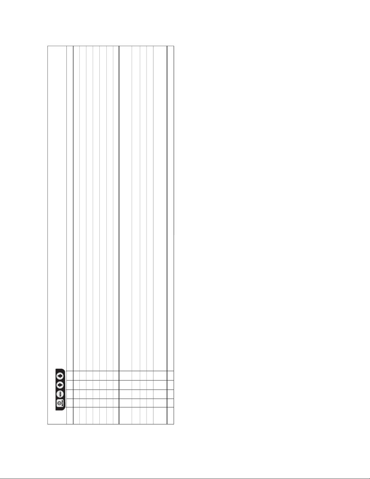
Table 2, Quick Reference Chart (QRC) • ZW Series Pallet Coupling Pumps • Firmware 7.x • Pump Program Number 9 (Continued)
Step Switch Text Expected reading / symbol / status Units Comments
I M t s display digital display
10 X ENGLISH select language, default is English
X ESPANOL
X FRANCAIS step through languages using either
X ITALIANO the Up- or the Down-Arrow button
X DEUTSCH
X PORTUGUES
X ENGLISH save with Menu button
11 the digital display is expected to show processor inputs
that are “turned on”
10001 with pendant Motor-button pushed
01001 with pendant Arrow-up button pushed
00101 with pendant Arrow-down button pushed
psi psi-reading present, if pressure transducer is attached and
has been recognized during boot-up
12 X READY hold for 2 seconds to return to “READY” run mode
13
Additional
Comments
Max value
for DWELL B
DWELL B
Action when
value is reached
Rapid valve cycle
~0.5 seconds after
motor shut down
command
to release pump
pressure after
motor stops
spinning.
Maximum
pressure
mechanically
limited to 5300-
5600 PSI by
intenal relief valve.
(even if PRESR A
or PRESR B value
is set higher)
Switches off.
Unclamping stops.
Actions
Max value
for PRESR B
PRESR B
Action when
value is reached
Max value
for DWELL A
DWELL A
Action when
value is reached
Max value
for PRESR A
PRESR A
Action when
value is reached
Button
On/Off
Arrow up Motor
10,500 psi Shuts off 60 seconds
Shuts off
immediately.
If DWELL B > 0,
10,500 psi Shuts off 60 seconds If DWELL B = 0,
Shuts off
immediately.
If DWELL A = 0,
If DWELL A > 0,
disabled
off off
Continues running.
Switches off.
Clamping stops.
clamping.
Switch off to stop
Continues running.
stays on and
If DWELL A > 0,
clamping continues.
Switches off.
Stays on and
If DWELL B > 0,
Unclamping stops.
continues.
Unclamping
440V 3 PH 50/60 Hz 460-480V 3 PH 50/60 Hz 575V 3 PH 50/60 Hz
Pendant Button LCD Panel
operation mode (“READY” is displayed on LCD)
What happens when _____ button is pushed in normal
Arrow
On/Off
Item Motor
switch
na-
disabled
Pump
Motor &
Option
(on-off
Fan Motor
(if equipped)
disabled)
Solenoid A na off on na If DWELL A = 0,
Solenoid B na on off na off off If DWELL B = 0,
RPM 115V 1 PH 50/60 Hz 208-240V 1 PH 50/60 Hz 190-200V 3 PH 50/60 Hz 208-240V 3 PH 50/60 Hz 380-415V 3 PH 50/60 Hz
kW
Table 4, Electrical Current Draw • ZW Series Pallet Coupling Pumps • Firmware 7.x • Pump Program Number 9
on on na-
down
Valve Pendant Foot
Table 3, Description of Automatic Operation • ZW Series Pallet Coupling Pumps • Firmware 7.x • Pump Program Number 9
Pump Information
Pump type
Pump
Pump
code
type
No.
ZWx4xxDx VEW43 3-button
Pallet
Coupling
9
Note - 5,000 PSI (350 bar)
1 0.75 1750 13.8 6.9 5.7 4.3 2.5 2.3 2.1 2.1
ZW3
1 0.75 1750 11.2 5.6 4.8 3.6 2 1.9 1.8 1.8
ZW4
1.5 1.12 1750 15.6 7.8 6.2 4.8 2.7 2.6 2.4 2.4
ZW5
hp
Pump Series Motor Size Maximum Current Draw (in amps)
14

L3075 Rev. A 04/14
Les vues éclatées de ce produit sont disponibles sur le
site Enerpac www.enerpac.fr. Vous pouvez également les
obtenir auprès de votre réparateur agréé Enerpac ou auprès
d’Enerpac même.
1.0 INSTRUCTIONS IMPORTANTES RELATIVES
À LA RÉCEPTION
Inspecter tous les composants pour vous assurer qu’ils n’ont
subi aucun dommage en cours d’expédition. Les dommages
subis en cours de transports ne sont pas couverts par
la garantie. S’ils sont abîmés, aviser immédiatement le
transporteur, qui est responsable des frais de réparation
et de remplacement résultant de dommages en cours de
transport.
LA SÉCURITÉ AVANT TOUT !
2.0 SÉCURITÉ
Lire attentivement toutes les instructions et
mises en garde et tous les avertissements.
Suivre toutes les précautions pour éviter
d’encourir des blessures personnelles ou de provoquer des dégâts
matériels durant le fonctionnement du système. Enerpac ne peut
pas être tenue responsable de dommages ou blessures résultant
de l’utilisation risquée du produit, d’un mauvais entretien ou d’une
application incorrecte du produit et du système. En cas de doute
sur les précautions ou les applications, contacter Enerpac.
Respecter les mises en garde et avertissements suivants sous
peine de provoquer des dégâts matériels et des blessures
corporelles.
Une mise en garde ATTENTION sert à indiquer des procédures
d’utilisation et de maintenance correctes qui visent à empêcher
l’endommagement voire la destruction du matériel ou d’autres
dégâts.
Un AVERTISSEMENT indique un danger potentiel qui exige la
prise de mesures particulières visant à écarter tout risque de
blessure.
La mention DANGER n’est utilisée que lorsqu’une action ou un
acte de négligence risque de causer des blessures graves, voire
mortelles.
AVERTISSEMENT : Porter un équipement de protection
individuelle adéquat pour utiliser un appareil hydraulique.
AVERTISSEMENT : Rester à l’écart de charges
soutenues par un mécanisme hydraulique. Un vérin,
lorsqu’il est utilisé comme monte-charge, ne doit jamais
servir de support de charge. Après avoir monté ou abaissé la
charge, elle doit être bloquée par un moyen mécanique.
DANGER : Pour écarter tout risque de blessures
corporelles, maintenir les mains et les pieds à l’écart
du vérin et de la pièce à usiner durant l’utilisation.
Fiche d’instructions
Pompes d’écartement de palette
Séries ZW3, ZW4 et ZW5
AVERTISSEMENT : Ne pas dépasser les valeurs
nominales du matériel. Ne jamais essayer de soulever
une charge d’un poids supérieur à la capacité du vérin.
Une surcharge entraînera la panne du matériel et risque de
provoquer des blessures corporelles. Les vérins sont conçus
pour une pression maximale de 350 bar. Ne pas connecter de
cric ou de vérin à une pompe affichant une pression nominale
supérieure.
DANGER : Ne jamais régler la soupape de sûreté à une
pression supérieure à la pression nominale maximale de
la pompe sous peine de provoquer des dégâts matériels
et/ou des blessures corporelles. Ne pas retirer le limiteur de
pression.
AVERTISSEMENT : La pression de fonctionnement du
système ne doit pas dépasser la pression nominale du
Installer des manomètres dans le système pour surveiller la
pression de fonctionnement. Ils permettent de vérifier ce qui se
passe dans le système.
fort retour de pression. Les plis et coudes prononcés
endommageront par ailleurs l’intérieur du flexible, provoquant son
usure précoce.
endommagé risque d’entraîner sa rupture.
manière sûre.
provoquera par conséquent des fuites. La chaleur affaiblit
également les matériaux et les garnitures du flexible. Pour une
composant du système affichant la plus petite valeur.
ATTENTION : Éviter d’endommager les flexibles
hydrauliques. Éviter de les plier et de les tordre en les
mettant en place. Un flexible plié ou tordu entraînera un
Ne pas faire tomber d’objets lourds sur le flexible. Un fort
impact risque de causer des dégâts intérieurs (flexible
®
métalliques). L’application d’ une pression sur un flexible
IMPORTANT : Ne pas soulever le matériel hydraulique
en saisissant ses flexible ou ses raccords articulés.
Utiliser la poignée de transport ou procéder d’une autre
ATTENTION : Garder le matériel hydraulique à l’écart
de flammes et d’une source de chaleur. Une forte
température amollira les garnitures et les joints et
15
performance maximale, ne pas exposer le matériel à une
température supérieure ou égale à 65 °C [150 °F]. Protéger
flexibles et vérins de projections de soudure.
DANGER : Ne pas manipuler les flexibles sous pression.
L’huile sous pression qui risque de s’en échapper peut
pénétrer dans la peau et provoquer des blessures graves.
En cas d’injection d’huile sous la peau, contacter immédiatement
un médecin.
AVERTISSEMENT : Utiliser des vérins hydrauliques
uniquement dans un système couplé. Ne jamais utiliser
un vérin en présence de raccords déconnectés. La
surcharge du vérin peut avoir des effets désastreux sur ses
composants, qui peuvent causer des blessures graves.
IMPORTANT : Le matériel hydraulique doit uniquement
être réparé par un technicien hydraulique qualifié. Pour
toute réparation, contacter le centre de réparation
ENERPAC agréé le plus proche. Pour assurer la validité de la
garantie, n’utiliser que de l’huile ENERPAC.
AVERTISSEMENT : Remplacer immédiatement les
pièces usées ou endommagées par des pièces ENERPAC
authentiques. Les pièces de qualité standard se casseront
et provoqueront des blessures et des dégâts matériels. Les
pièces ENERPAC sont conçues pour s’ajuster parfaitement et
résister à de fortes charges.
ATTENTION : N’utilisez pas de pompe électrique en
atmosphère explosive. Respectez toutes les
réglementations électriques. L’installation ainsi que
toutes modifications doivent obligatoirement être effectuées par
un technicien qualifié.
ATTENTION : Démarrez la pompe avec le distributeur en
position neutre pour éviter tout mouvement accidentel
du vérin. Tenez vos mains éloignées des pièces en
mouvement et des flexibles sous pression.
ATTENTION : Ces pompes sont équipées de vannes
réglées en usine ; celles-ci ne sont réparables ou
réglables que par un centre de service agréé Enerpac.
ATTENTION : Pour éviter d’endommager le moteur
électrique de la pompe, vérifiez ses caractéristiques.
Une alimentation électrique incorrecte provoquera des
dommages au moteur.
3.0 SPÉCIFICATIONS
3.1 Diagrammes de débit (voir la figure 1)
3.2 Tableaux de rendement (voir la figure 1)
3.3 Appel de courant électrique (se reporter au Tableau
4 de la section 8.0 de ce manuel)
COURBES DE DÉBITS
16
13
10
7
Débit d’huile (l/min)
3
0
0 35028021014070
Série ZW3 à deux étages
TABLEAU DES PERFORMANCES
Série
Pompes
Série ZW3
Pression (bar)
Fonctionnement
7 bar 50 bar 350 bar kw RPM (bar) (dBA)
16
13
10
7
Débit d’huile (l/min)
3
0
0 35028021014070
Série ZW4 à un étage
Série ZW4 à deux étages
Débit nominal
l/min
ZW3 Deux étages 3,3 3,1 0,6
Un étage 1,0 1,0 1,0
ZW4
Deux étages 5,7 5,0 1,0
Un étage 2,1 2,1 2,0
ZW5
Deux étages 10,6 9,9 2,0
Série ZW4
Pression (bar)
Série ZW5
sécurité
70 - 350
Débit d’huile (l/min)
Puissance
du moteur
0,75 1750
16
13
10
7
3
0
0
Série ZW5 à un étage
Série ZW5 à deux étages
Plage de réglage
de la soupape de
1,12 1750 70 - 350
Pression (bar)
35028021014070
Niveau sonore
75
75
Le débit nominal indiqué est de 60 Hz.
Le débit atteindra approximativement 5/6 de ces valeurs à 50 Hz.
Figura 1, spécifications de la pompe
16
A
B
A
B
Figure 2, Installation du reniflard pour la série ZW
C
D
4.0 INSTALLATION
Installez ou positionnez la pompe afin de s’assurer que la
circulation d’air autour du moteur et de la pompe ne soit
pas obstruée. Gardez le moteur propre afin d’assurer un
refroidissement maximal pendant le fonctionnement.
4.1 Reniflard du réservoir (voir la figure 2)
Pour le transport, un bouchon d’expédition (A) est installé dans
l’ouverture du reniflard située sur le dessus du réservoir. Avant
d’utiliser l’appareil, remplacez le bouchon d’expédition (A) par
le reniflard (B).
Remarque : Le port de remplissage d’huile est muni d’un
bouchon SAE nº 10 (C), installé à l’extrémité de la rallonge du
tuyau de remplissage (D).
4.2 Plan de fixation
Consultez la Figure 3 pour les dimensions du support pour fixer
la pompe à une surface fixe.
4-8 L 10 L 20 L 40 L
mm mm mm mm
A 95 279 396 480
B 229 305 305 305
C M8, 12 mm Ø 8.6 diamètre à travers le trou
(6) en profondeur
C
4.3 Connexions électriques
LA POMPE A ÉTÉ MUNIE EN USINE D’UNE PRISE
ÉLECTRIQUE STANDARD NORMAL POUR UNE TENSION
DONNÉE. LA MODIFICATION DU TYPE DE PRISE DOIT
ÊTRE FAITE SEULEMENT PAR UN ÉLECTRICIEN QUALIFIÉ,
EN RESPECTANT TOUTES LES NORMES LOCALES ET
NATIONALES APPLICABLES.
1. Le sectionneur et la protection du circuit de la ligne
d’alimentation doivent être fournis par le client. La protection
pour le circuit de la ligne d’alimentation doit être établie à
115 % du débit maximal du moteur en utilisation à pression
maximale.
2. Pour obtenir de plus amples renseignements, référez-vous à
la plaque d’identification pour connaître la puissance
nominale.
Se reporter aussi au Tableau 4 de la Section 8.0 pour
l’information sur l’appel de courant du moteur.
4.4 Niveau d’huile
Vérifiez le niveau d’huile du moteur avant le démarrage. Si le
niveau d’huile est bas, retirez le bouchon SAE nº 10 de la rallonge
du tuyau de remplissage et ajouter de l’huile au besoin (voir la
figure 1).
Le réservoir est plein lorsque le niveau d’huile est au niveau
illustré dans la figure 4.
Le réservoir est
plein lorsque
l’huile a atteint
ce niveau.
(0,88 et 1,76 gal)
4 et 8 litres
10 à 40 litres
(2,20 à 8,80 gal)
Figure 4
B
Figure 3
IMPORTANT : ajoutez de l’huile seulement lorsque les
composants sont complètement rétractés, sinon le système
contiendra plus d’huile que peut en contenir le réservoir.
17
4.5 Liaisons hydrauliques
Figure 5
Appliquez 1 tour et demi de
bande Téflon ou tout autre
adhésif adéquat à l’installation
du flexible hydraulique, en
laissant le premier filet complet
sans bande ou adhésif comme
montré dans la Figure 5.
Flèche vers le haut
®
Flèche vers le bas
ON/OFF (désactivée –
hors tension)
Vissez le ou les tuyaux flexibles dans le ou les ports de sortie de
la soupape (les ports de sortie de la soupape sont identifiés sur
le corps de la soupape).
Brancher le flexible de serrage (allongé) à l’orifice de vanne “A”.
Brancher le flexible de desserrage (rétracté) à l’orifice de vanne
“B”.
Si vous le souhaitez, un manomètre peut être installé dans l’orifice
de vanne “GA” ou “GB”.
Remarque : “GA” mesure la pression de l’orifi ce “A”, “GB” mesure
la pression de l’orifi ce “B”, “GP” mesure la pression de la pompe
en aval du contrôle du système. Le transducteur de pression de la
pompe est installé en usine dans l’orifi ce “GP” et doit resté installé
à cet endroit pour garantir le bon fonctionnement de la pompe.
5.0 FONCTIONNEMENT
AVERTISSEMENT : Revoir les sections 5.1-5.4 et 6.1-
6.4 avant de démarrer la pompe. S’assurer que le mode
de fonctionnement Dwell et les fonctions sont clairement
compris avant de relier le module à une source de courant.
1. Vérifiez le niveau d’huile de la pompe et ajoutez de l’huile au
besoin.
2. Assurez-vous que le bouchon d’expédition a été retiré et que
le reniflard est bien installé. (Voir la section 4.1)
3. Branchez l’unité à l’alimentation. Attendez que l’écran
ACL affiche « PRET » avant d’appuyer sur tout bouton du
carénage ou de la télécommande. Remarque: Pendant la
séquence de démarrage, le microcontrôleur identifie toute
utilisation d’un bouton comme une défaillance potentielle
et empêche le moteur de démarrer. Pour réinitialiser le
démarrage, coupez l’alimentation de l’appareil pendant
trente
secondes.
4. Pour un aperçu du fonctionnement de la pompe, y compris
les fonctions de la télécommande, se reporter aux sections
5.1-5.4. Pour des consignes détaillées sur le fonctionnement
du panneau de commande LCD, voir sections 6.1-6.4.
5.1 Fonctionnement de la télécommande
(voir la figure 6)
Le débit d’huile et le moteur sont tous deux contrôlés par les
commandes de la télécommande. La pompe démarre et le
piston se serre lorsqu’on enfonce le bouton de flèche vers le
haut de la télécommande. La pompe démarre et le piston se
desserre lorsqu’on enfonce le bouton de flèche vers le bas
de la télécommande. Lorsqu’on relâche l’un ou l’autre de ces
boutons, la pompe s’arrête et la pression se décharge dans les
flexibles (voir la figure 6).
1. Flèche vers le haut = moteur sous tension - serrage courte
durée
2. Flèche vers le bas = moteur sous tension - desserrage
courte durée
3. On/Off – non utilisée (désactivée)
Carénage On/Off – non utilisée (désactivée)
Figure 6
5.2 Option d’interrupteur au pied
(voir la figure 7).
1. Moteur sous tension – serrage
courte durée
2. Moteur sous tension – desserrage
courte durée
Carénage On/Off = non utilisée
(désactivée)
Figure 7
5.3 Fonctionnement du mode Dwell automatique
Le mode Dwell permet à la pompe de réagir automatiquement
selon deux valeurs de pression définies par l’utilisateur, «
PRESR A » et « PRESR B ». Cette fonction peut être activée
et désactivée tel que désiré. Voir les paragraphes suivants
pour obtenir des informations supplémentaires. Référez-vous
aussi à la section 6.2 pour obtenir plus de détails concernant le
fonctionnement et le réglage du mode Dwell.
1. Mode Dwell Off
Le panneau de commande LCD de la pompe indique la pression
comme un simple manomètre. Aucune action supplémentaire ne
sera menée quelques soient les valeurs PRESR A et PRESR B.
2. Mode Dwell On
La pompe désactivera le moteur et le solénoïde de la soupape
dès que la valeur de pression PRESR A ou PRESR B spécifiée
sera atteinte et que la durée (en secondes) de la fonction
Dwell sera écoulée. Lorsque la pompe s’arrête, la pression des
flexibles tombe à zéro (0) pour que les coupleurs puissent être
déconnectés de la palette.
Remarque: « AUTO » s’affiche sur le panneau ACL lorsque le
mode Dwell est activé. « PRET » s’affiche lorsque le mode Dwell
est désactivé.
5.3.1 Aperçu du mode Dwell
Avant que la valeur PRESR A ou PRESR B soit atteinte :
• Les boutons de flèche vers le haut et de flèche vers le bas
de la télécommande fonctionnent tel qu’indiqué dans la
section 5.1.
Après que la valeur PRESR A ou PRESR B soit atteinte :
• Tenez le bouton de flèche enfoncé vers le haut ou le
bas après que la valeur de pression ait été atteinte pour
activer la minuterie de la fonction dwell. Le rétroéclairage
de l’écran ACL clignotera et la pompe continuera à
fonctionner jusqu’à la fin de la période d’exécution de la
fonction dwell définie par l’utilisateur (1 à 60 secondes).
• Afin d’assurer un serrage et un desserrage appropriés, les
boutons des flèches vers le haut et vers le bas doivent
demeurer enfoncés jusqu’à l’arrêt de la pompe.
• Le relâchement d’un de ces boutons (flèche vers le haut
ou vers le bas) arrêtera automatiquement le cycle et l’écran
ACL arrêtera de clignoter.
18
 Loading...