

Page 1
L4080
Rev. C 02/15
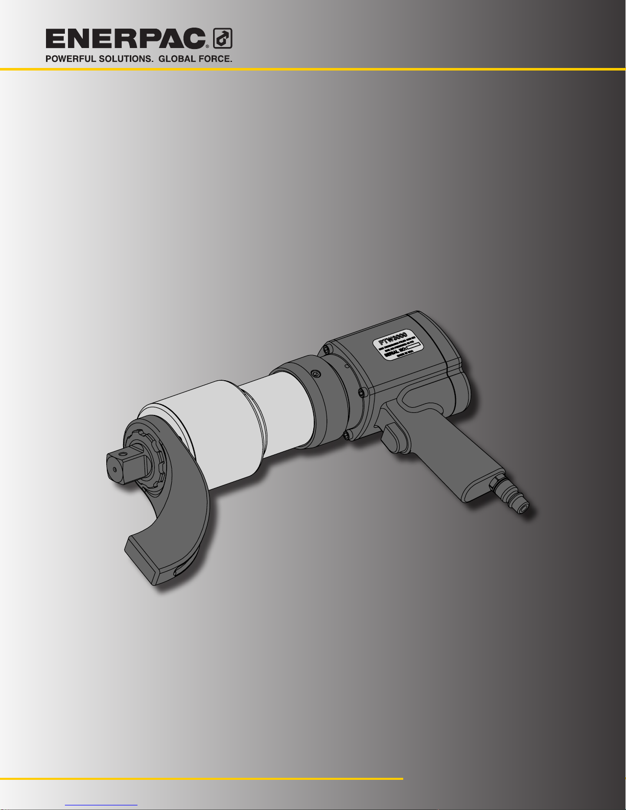
Pneumatic
Torque
Wrench
PTW Series
English (EN)
PTW1000
PTW2000
PTW3000
PTW6000
Instruction Sheet
Page 2
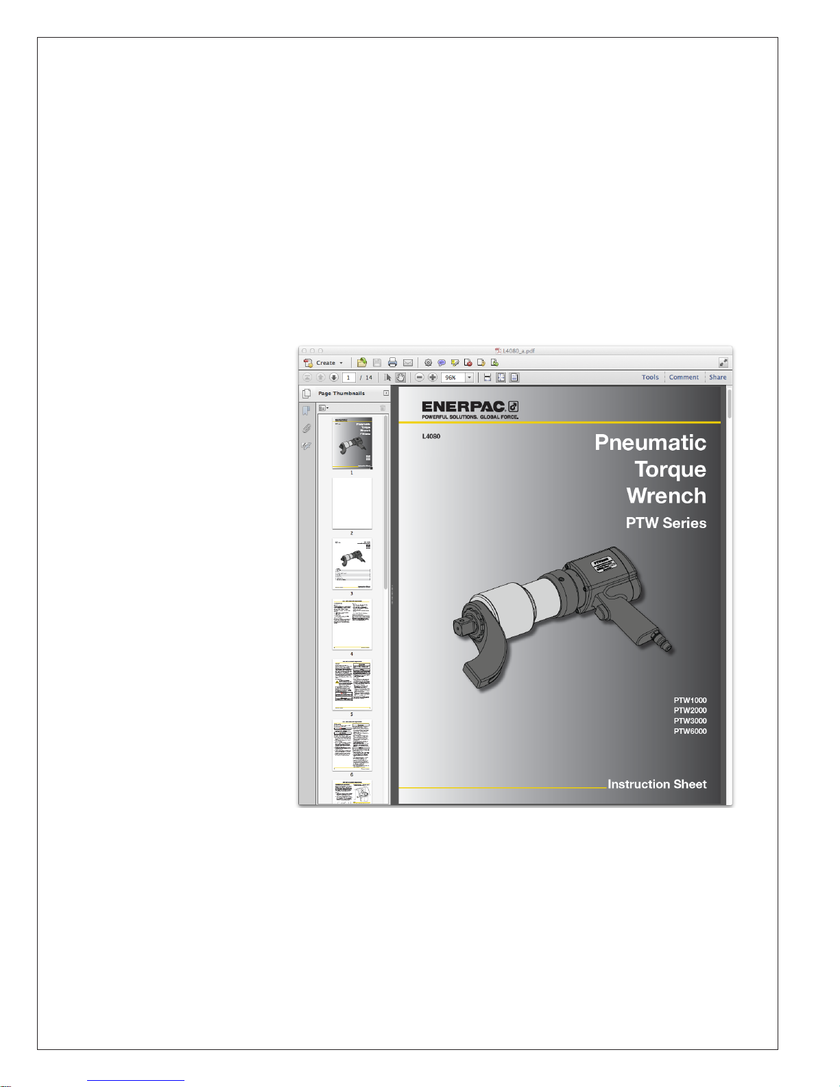
Instruction Sheets in Adobe® PDF format
Please find the CD or DVD enclosed in the back of this manual
The following languages
are included:
English (EN)
Français (FR)
Deutsch (DE)
Italiano (IT)
Español (ES)
Nederlands (NL)
Português Brasileiro (PT)
Norsk (NO)
Suomi (FI)
Pyccкий (RU)
简体中文 (ZH)
日本語 (JA)
한국어 (KO)
Svenska (SV)
Romanian (RO)
Polish (PL)
Czech (CS)
Note: Download the latest version of Adobe Reader at:
http://get.adobe.com/reader
Page 3
L4080
Rev.C 02/15
PTW Series
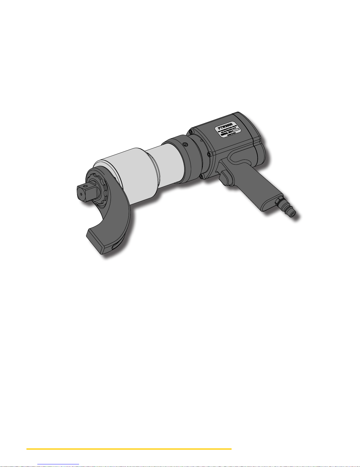
Pneumatic Torque Wrench
PTW1000
PTW2000
PTW3000
PTW6000
Index
1 Introduction .................................................................................................................................... 2
2 Safety .............................................................................................................................................. 3
3 Assembly and Adjustment ............................................................................................................ 5
4 Operation ........................................................................................................................................ 6
5 Maintenance ................................................................................................................................... 9
6 Troubleshooting ............................................................................................................................. 9
7 Technical Specifications .............................................................................................................. 10
© 2015 Enerpac, All Rights Reserved
Instruction Sheet
Page 4
PTW Series Pneumatic Torque Wrench
1 INTRODUCTION
Overview
The Enerpac PTW Series torque wrench is designed
for controlled tightening and loosening of fasteners
in industrial bolting applications. Optional reaction
arms are available for dierent applications.
The PTW Series is available as a package with the
following:
• 1 PTW Series Pneumatic Torque Wrench
• 1 Standard Reaction Arm
• 1 Storage Case
• 1 Air Hose (10 ft)
• 1 Air Filter Regulator Lubricator Unit (FRL)
Delivery Instructions
Upon delivery, all components must be inspected
for damage incurred during shipping. If damage
is found, the carrier should be notified at once.
Shipping damage is not covered by the Enerpac
warranty.
Warranty
• Enerpac guarantees the product only for the
purpose for which it is intended.
• All Enerpac products are guaranteed against
defects in workmanship and materials for as
long as you own them. Any misuse or alteration
invalidates the warranty.
• Observe all instructions as communicated in this
manual.
• Use only genuine Enerpac replacement parts.
CE Declaration of Conformity
PTW1000 • PTW2000 • PTW3000 • PTW6000
Enerpac declares that the PTW Series pneumatic
torque wrenches meet the applicable standards and
directives issued by the European Union.
2 © 2015 Enerpac, All Rights Reserved
Page 5
PTW Series Pneumatic Torque Wrench
2 SAFETY
Read all instructions carefully. Follow all
recommended safety precautions to avoid personal
injury as well as damage to the wrench and/or
damage to other property. Enerpac cannot be
responsible for any damage or injury from unsafe use,
lack of maintenance or incorrect operation. Do not
remove warning labels, tags or decals. In the event
any questions or concerns arise, contact Enerpac or
a local Enerpac distributor for clarification.
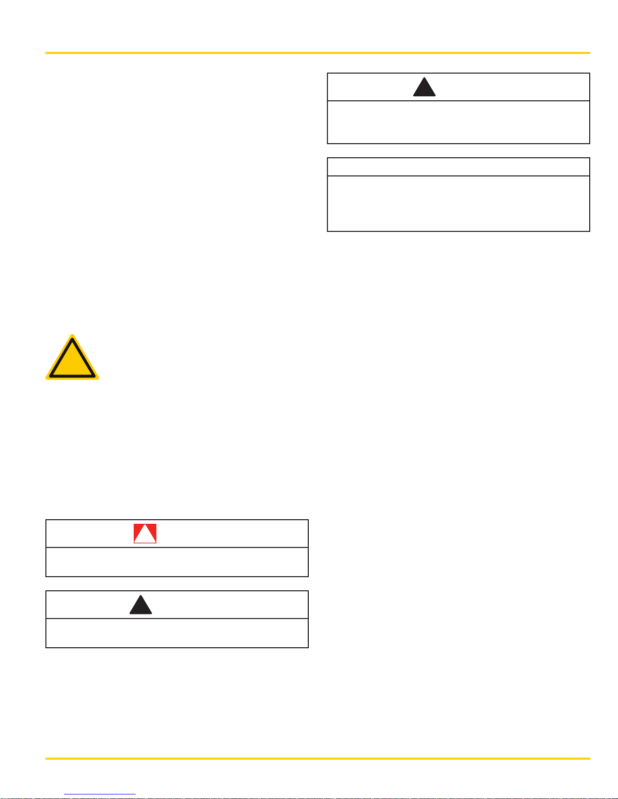
This manual follows a system of safety alert symbols,
signal words and safety messages to warn the user
of specific hazards. Failure to comply with these
warnings could result in death or serious personal
injury, as well as damage to the equipment or other
property.
!
CAUTION
Indicates a hazardous situation, if not avoided,
could result in minor or moderate personal
injury.
NOTICE
Indicates information considered important but not
hazard-related (e.g., messages relating to property
damage). Please note that the Safety Alert Symbol
will not be used with this signal word.
NOTE: Indicates a procedure, practice or condition
that should be followed in order for the tool to
function in the manner intended.
General Safety
Safety Definitions
The Safety Alert Symbol appears
throughout this manual. It is used to alert
!
Safety Alert Symbols are used in conjunction with
certain Signal Words that call attention to safety
messages or property damage messages and
designate a degree or level of hazard seriousness.
The Signal Words used in this manual are DANGER,
WARNING, CAUTION and NOTICE.
Indicates a hazardous situation, if not avoided,
will result in death or serious personal injury.
Indicates a hazardous situation, if not avoided,
could result in death or serious personal injury.
you to potential physical injury hazards.
Pay close attention to Safety Alert Symbols
and obey all safety messages that follow
this symbol to avoid the possibility of
death or serious personal injury.
!
DANGER
!
WARNING
Be aware that the operator is fully responsible for
the correct operation of this tool. Enerpac is not
responsible for damage or injury caused by misuse
of this tool. Under some circumstances, additional
safety precautions beyond those described in this
manual may be required. Read this manual carefully
and observe all safety precautions.
• Be sure you have read and understood the
instruction manual prior to using the tool.
Contact Enerpac if you have questions.
• Make sure you have completed safety training,
specific to the work surroundings. The operator
should be thoroughly familiar with the controls
and the proper use of the tool.
• The operator must be of at least the minimum
age required by applicable local regulations, laws
and the facility’s standard operating procedures.
• Make sure your workplace is safe.
Follow instructions in your workplace’s standard
operating procedures and be sure to observe all
communicated safety precautions.
© 2015 Enerpac, All Rights Reserved 3
Page 6
PTW Series Pneumatic Torque Wrench
PTW Series Safety
The following warnings are specific to the PTW
Series Pneumatic Torque Wrench.
!
DANGER
!
CAUTION
Failure to observe and comply with the following
precautions could result in minor or moderate
personal injury. Property damage could also occur.
• Do not place any part of the body between the
reaction arm and the reaction point.
!
WARNING
Failure to observe and comply with the following
precautions could result in death or serious
personal injury. Property damage could also occur.
• Be aware that a nut or bolt that breaks o during
operation of the tool may become a high-velocity
projectile.
• Never exceed the maximum air pressure shown
on the supplied chart.
• Always wear protective headwear, ear protectors,
footwear and gloves (at a minimum, rigger-type
gloves) suitable for safe operation of the tool.
The protective clothing must not interfere with
safe operation of the tool or restrict the ability to
communicate with coworkers.
• Do not place any objects between the reaction
arm and the reaction point. Keep the hoses away
from the reaction points.
• Tightening and loosening nuts and bolts involves
little visible movement. The pressure and loads,
however, are extreme. Keep your hands away
from the fastener being loosened or tightened.
• Keep loose clothing, hair and other items from
being caught in any rotating part of the tool.
• Make sure the air supply is o prior to attaching
or removing couplings or hoses. Be certain that
all hose couplings are fully connected before
applying air pressure.
• Always use sockets which are designed for use
with powered wrenches.
• Always position the tool for maximum stability.
Make sure reaction points are adequate for the
forces at work during operation of the tool.
• Make sure the reaction point is of a suitable
shape. For example, use an adjacent nut or bolt
as a reaction point.
• The maximum torque output rating of the tool
must always exceed the torque required to
loosen or tighten the nut or bolt.
• Do not drop heavy objects on the hose. A sharp
impact may cause internal damage to the hose.
Applying pressure to a damaged hose may cause
it to burst.
NOTICE
Failure to observe and comply with the following
precautions could result in property damage and/
or void the product warranty.
• Never use the air hoses to carry or move the tool
or the Filter/Regulator/Lubricator (FRL) assembly.
• If the tool is dropped from a significant height,
have the tool inspected before you operate it
again.
• In severe conditions, the tool must be cleaned
and inspected more frequently.
• Be sure to minimize torsional and bending
stresses in the tool and any accessories.
• Avoid striking the tool at any time, even when it
is not under load. Striking the tool could cause
permanent damage to wrench components and
may aect the wrench calibration.
• Always use Enerpac spare parts.
• Ensure that the tool and related equipment are in
good working condition prior to use.
4 © 2015 Enerpac, All Rights Reserved
Page 7
PTW Series Pneumatic Torque Wrench
3 ASSEMBLY AND ADJUSTMENT
The air source must be capable of at least 50 CFM
(85 CMH) at 100 psi (6.9 bar). A minimum hose size
of 1/2 inch (13 mm) must be used. The tool must be
calibrated with the Filter/Regulator/Lubricator (FRL)
that is being used. The PTW equipment (including
tool and FRL) is to be used with an air supply that
is regulated and/or limited to 120 psi (8.3 bar)
maximum.
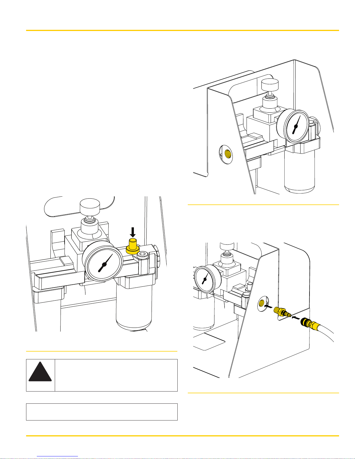
1. Check the air lubricator oil level and fill if needed.
Only use SAE 10 or lighter clean, nondetergent
oil. Remove the cap and add oil if needed.
2. Turn the drip rate adjustment knob to adjust the
drip rate. The drip rate can be viewed through the
clear adjustment knob. The drip rate should be
checked while the tool is operating. Set the drip
rate to between 4 and 6 drops per minute.
3. Install a quick coupler or air hose (not supplied)
into the 1/2 inch NPT inlet port.
Fig. 2
Fig. 1
!
WARNING: To prevent hazards created
by hose whip, securely connect all
connections before turning on the air
supply.
4. Install the supplied male quick coupler into the
outlet port.
5. Connect the air hose to the male quick coupler.
Fig. 3
NOTICE: Make sure hoses are free of debris and
the ends are clean before connecting.
© 2015 Enerpac, All Rights Reserved 5
Page 8
PTW Series Pneumatic Torque Wrench
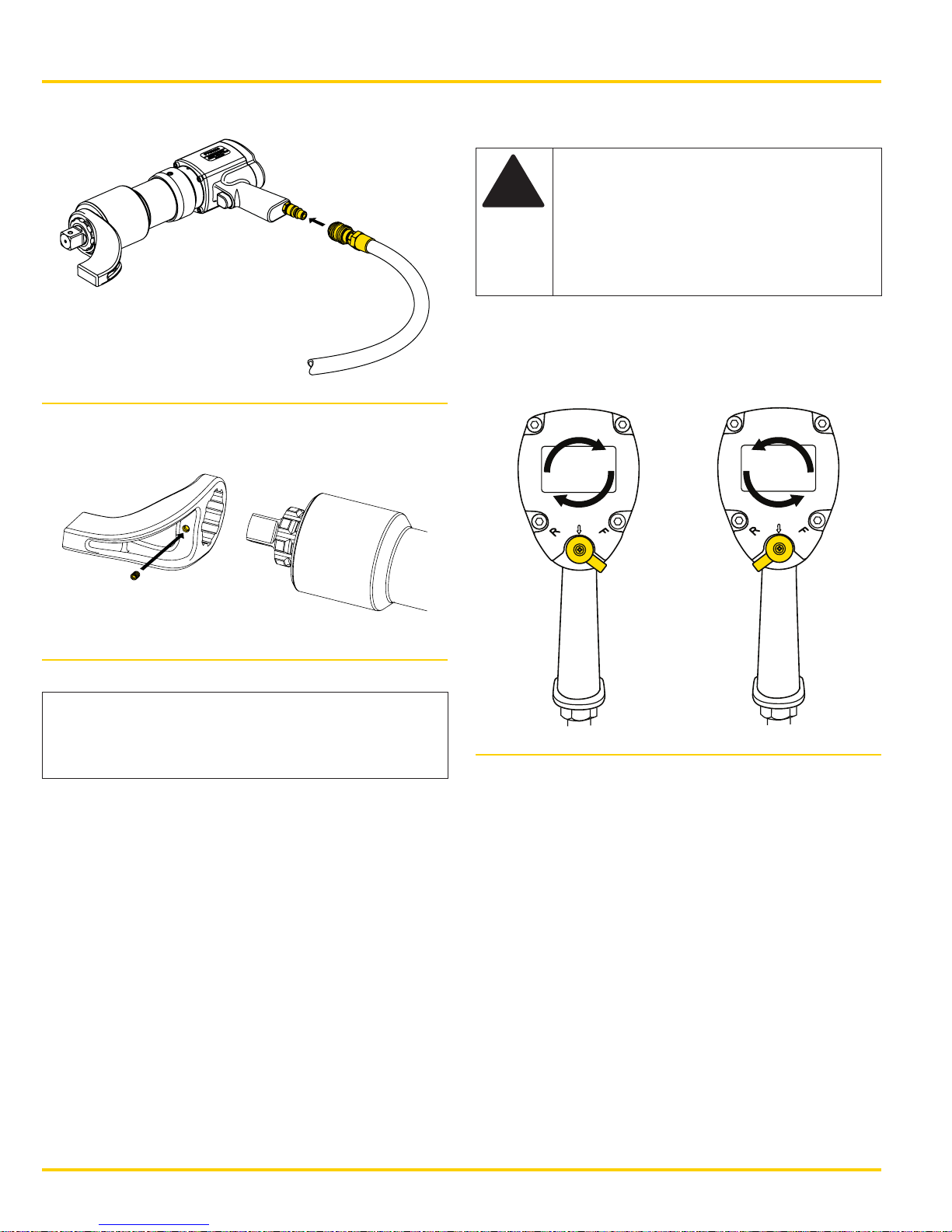
6. Connect the air hose to the tool.
Fig. 4
7. Install the reaction arm onto the tool. Tighten the
setscrew to secure it on the tool.
4 OPERATION
WARNING: Before using the tool,
!
1. To rotate the tool clockwise, move the
lever to the “F” position. To rotate the tool
counterclockwise, move the lever to the “R”
position. There are 3 speeds for each direction.
inspect the tool, reaction arm, air
hoses and Filter/Regulator/Lubricator
(FRL) for any cracks, wear or other
damage. Immediately replace any
worn or damaged parts with genuine
Enerpac parts before using the tool.
3
2
3
2
1
1
2
3
1
1
2
3
Fig. 5
NOTICE: Thread the setscrew in just deeply
enough to catch the retaining shoulder. Bottoming
out the screw can cause thread damage during
operation, making it dicult to remove.
8. Turn on the air supply.
Fig. 6
6 © 2015 Enerpac, All Rights Reserved
Page 9
PTW Series Pneumatic Torque Wrench
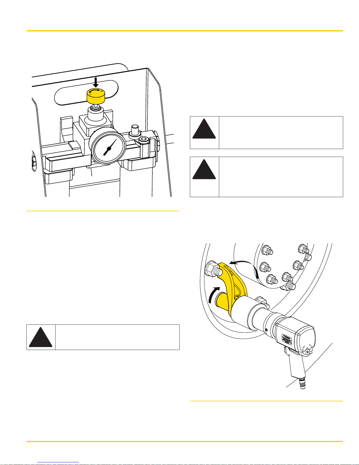
2. The torque output of the tool is set by adjusting
the air pressure using the regulator on the FRL.
Fig. 7
3. Determine the correct air pressure for the desired
torque setting by using the chart from the most
recent calibration. A factory calibration chart is
provided by Enerpac in the tool case.
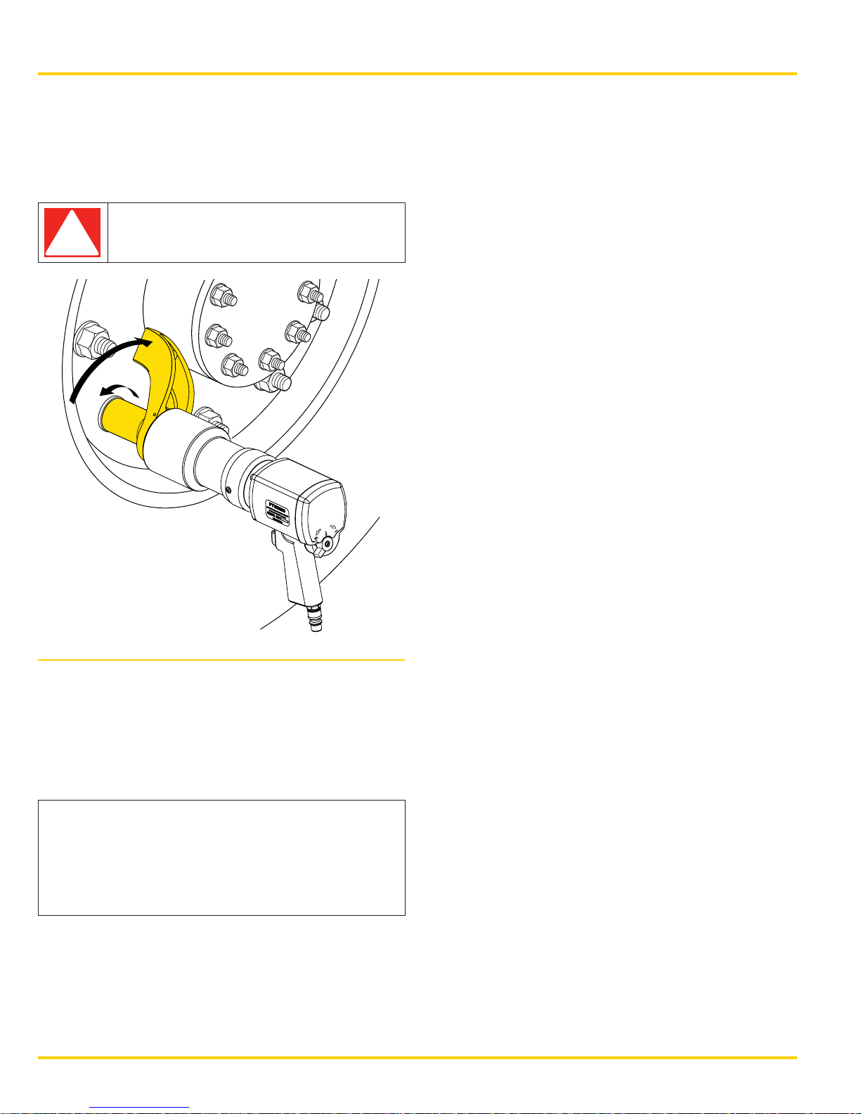
6. Make sure the appropriate reaction arm is
installed onto the tool.
7. Determine the correct size socket and install it
on the square drive. It is recommended that the
socket be pinned onto the square drive.
8. Install the socket onto the fastener and rotate the
body so the reaction arm is positioned against
the reaction point.
WARNING: To prevent serious
!
!
NOTE: For clockwise rotation, the adjustment lever is
set to the “F” position.
9. Fig. 8 shows the position for the reaction arm
when the square drive rotates clockwise.
crushing injury, always keep all body
parts away from the reaction point
when the tool is in use.
CAUTION: When in operation, the
reaction arm rotates in the opposite
direction of the square drive. Always
make sure the reaction arm is
positioned against a solid fixed object.
4. Adjust the lever on the back of the tool indicated
in Fig. 6 so the tool is set to the highest speed
and direction of rotation.
The tool calibration chart provided by Enerpac for
this tool was produced with the tool on the highest
speed. Tool performance in this speed will most
closely reproduce the pressure/torque ratio listed in
this chart.
WARNING: Do not attempt to operate
!
NOTE: For an accurate torque value, the air pressure
must be adjusted with the tool free-running (rotating
freely, not under load).
5. Fully depress the trigger of the tool and adjust
the regulator to the correct pressure while the
tool is free-running.
the tool at pressures exceeding the
torque ratings from the supplied chart.
Fig. 8
© 2015 Enerpac, All Rights Reserved 7
Page 10
PTW Series Pneumatic Torque Wrench
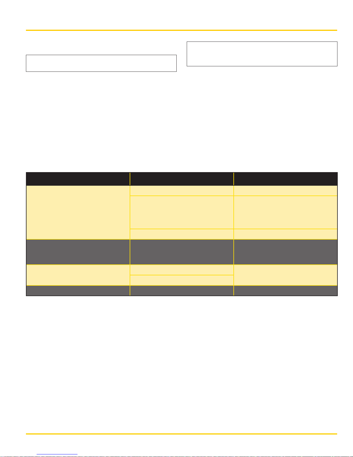
NOTE: For counterclockwise rotation, the adjustment
lever is set to the “R” position.
10. Fig. 9 shows the position for the reaction arm
when the square drive rotates counterclockwise.
DANGER: Do not place any part of the
!
body between the reaction arm and
the reaction point.
12. To loosen a fastener (or to apply torque in the
counterclockwise direction): Be sure that the
adjustment lever is set to the “R” position and
that the reaction arm is positioned as shown in
Fig. 9. Then, fully depress the trigger and keep it
depressed until the fastener loosens.
13. After tightening or loosening is completed,
release the trigger and remove the tool from the
fastener. In some cases, it may be necessary to
briefly operate the tool in the opposite direction
to release the counter torque load from the
reaction arm.
14. When finished using the tool, turn o the air
supply, disconnect the hoses, remove the
reaction arm and store the tool in the case.
Fig. 9
11. To tighten a fastener (or to apply torque in the
clockwise direction): Be sure the adjustment lever
is set to the “F” position, and that the reaction
arm is positioned as shown in Fig. 8. Then, fully
depress the trigger, and keep it depressed until
the wrench stalls.
NOTICE: If the trigger is released before the
wrench stalls, the desired torque will not be applied
to the fastener. Do not repeatedly depress and
release the trigger while tightening a fastener,
as this could result in the incorrect torque being
applied.
8 © 2015 Enerpac, All Rights Reserved
Page 11
PTW Series Pneumatic Torque Wrench
5 MAINTENANCE
NOTICE: Failure to keep the air motor properly
lubricated can cause a reduction in output torque.
A constant source of clean and lubricated air is
required to ensure proper operation of the air motor’s
internal components.
Periodically check the oil level in the FRL lubricator
bowl and add oil if low. Check the oil drip rate and
readjust drip speed if too slow or too fast.
6 TROUBLESHOOTING
Symptom Possible Cause Solution
Tool is not producing required
torque.
Inadequate incoming air. Check pressure setting on FRL.
Inadequate lubrication. After shutting down the FRL,
NOTICE: Failure to maintain proper lubricator oil
level and drip rate will result in reduced output
torque and possible air motor failure.
Drain the water separator bowl as needed. Clean
and/or replace filter elements inside the bowl.
remove the air fitting coupler from
the tool. Add 1/2 teaspoon of oil
and install the air fitting coupler.
Motor contamination. Contact Enerpac Service Center.
Noticeable changes in sound
level during operation from one
fastening to the next.
Motor turns but there is no torque
output.
Noisy gearbox. Gearbox failure. Contact Enerpac Service Center.
Inadequate lubrication. Increase the drip rate for the FRL.
Recheck and reset drip rate if
necessary.
Broken square drive. Contact Enerpac Service Center.
Internal gearbox failure.
© 2015 Enerpac, All Rights Reserved 9
Page 12
PTW Series Pneumatic Torque Wrench
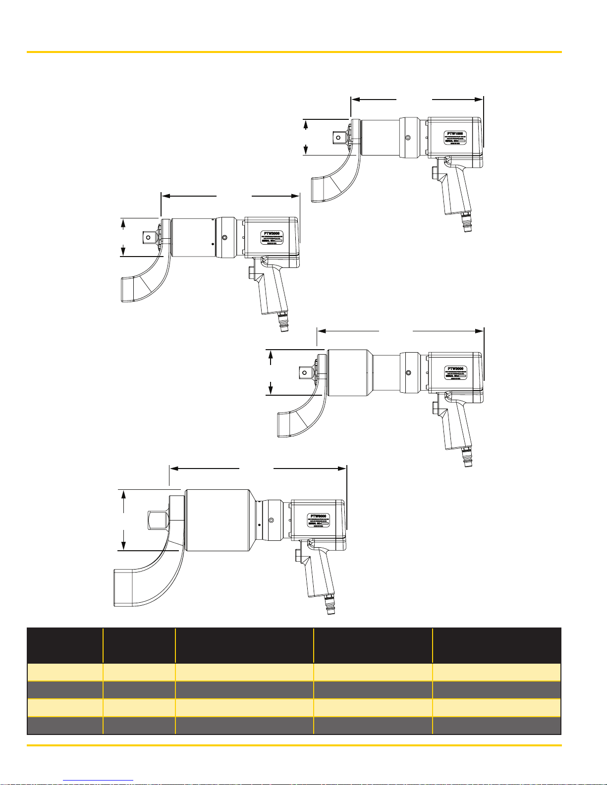
10.70 in.
7 TECHNICAL SPECIFICATIONS
11.26 in.
(286 mm)
Ø 3.11 in.
(79 mm)
PTW2000
Ø 2.83 in.
(72 mm)
(272 mm)
PTW1000
Ø 5.0 in.
(127 mm)
Ø 3.74 in.
(95 mm)
14.4 in.
(366 mm)
PTW6000
13.5 in.
(343 mm)
PTW3000
Tool Model Tool
lb (kg)
Supplied Reaction Arm
lb (kg)
Minimum Output
ft-lb (Nm)
Maximum Output
ft-lb (Nm)
PTW1000 18 (8.16) 2.85 (1.29) 300 (407) 1,000 (1,356)
PTW2000 19.5 (8.85) 2.85 (1.29) 500 (678) 2,000 (2,712)
PTW3000 23 (10.43) 2.85 (1.29) 900 (1,220) 3,000 (4,067)
PTW6000 39 (17.69) 7.75 (3.52) 1,300 (1,763) 6,000 (8,135)
10 © 2015 Enerpac, All Rights Reserved
Page 13

PTW Series Pneumatic Torque Wrench
NOTES
_____________________________________________________________________________
_____________________________________________________________________________
_____________________________________________________________________________
_____________________________________________________________________________
_____________________________________________________________________________
_____________________________________________________________________________
_____________________________________________________________________________
_____________________________________________________________________________
_____________________________________________________________________________
_____________________________________________________________________________
_____________________________________________________________________________
_____________________________________________________________________________
_____________________________________________________________________________
_____________________________________________________________________________
_____________________________________________________________________________
_____________________________________________________________________________
_____________________________________________________________________________
_____________________________________________________________________________
_____________________________________________________________________________
© 2015 Enerpac, All Rights Reserved 11
Page 14

PTW Series Pneumatic Torque Wrench
NOTES
_____________________________________________________________________________
_____________________________________________________________________________
_____________________________________________________________________________
_____________________________________________________________________________
_____________________________________________________________________________
_____________________________________________________________________________
_____________________________________________________________________________
_____________________________________________________________________________
_____________________________________________________________________________
_____________________________________________________________________________
_____________________________________________________________________________
_____________________________________________________________________________
_____________________________________________________________________________
_____________________________________________________________________________
_____________________________________________________________________________
_____________________________________________________________________________
_____________________________________________________________________________
_____________________________________________________________________________
_____________________________________________________________________________
12 © 2015 Enerpac, All Rights Reserved
Page 15
Please contact Enerpac if the disc is not included,
or visit www.enerpac.com for a download of the manual.
Instruction Sheets
PTW Series
Pneumatic Torque
Wrenches
PTW1000, PTW2000
PTW3000, PTW6000
Page 16

Australia and New Zealand
Actuant Australia Ltd.
Block V Unit 3
Regents Park Estate
391 Park Road
Regents Park NSW 2143
(P.O. Box 261) Australia
T +61 (0)2 9743 8988
F +61 (0)2 9743 8648
[email protected]
Brazil
Power Packer do Brasil Ltda.
Rua
Luiz Lawrie Reid, 548
09930-760
-
Diadema (SP) - Brazil
T +55 11 5687 2211
Toll Free: 0800 891 5770
[email protected]
China
(Taicang)
Actuant (China) Industries Co. Ltd.
No. 6 Nanjing East Road,
Taicang Economic Dep Zone
Jiangsu, China
T +86 0512 5328 7500
F +86 0512 5335 9690
Toll Free: +86 400 885 0369
[email protected]
France, Switzerland, North Africa
and French speaking African
countries
ENERPAC
Une division d’ACTUANT France S.A.S.
ZA de Courtaboeuf
32, avenue de la Baltique
91140 VILLEBON /YVETTE
France
T +33 1 60 13 68 68
F +33 1 69 20 37 50
[email protected]
Germany and Austria
ENERPAC GmbH
P.O. Box 300113
D-40401 Düsseldorf
Willstätterstrasse 13
D-40549 Düsseldorf, Germany
T +49 211 471 490
F +49 211 471 49 28
[email protected]
India
ENERPAC Hydraulics (India) Pvt. Ltd.
No. 10, Bellary Road,
Bangalore,
Karnataka
Sadashivanagar,
560 080
India
T
+91 80 3928 9000
[email protected]
www.enerpac.com
Italy
ENERPAC S.p.A.
Via Canova 4
20094 Corsico (Milano)
T +39 02 4861 111
F +39 02 4860 1288
[email protected]
Japan
Applied Power Japan LTD KK
Besshocho 85-7
Kita-ku, Saitama-shi 331-0821, Japan
T +81 48 662 4911
F +81 48 662 4955
[email protected]
Middle East, Egypt and Libya
ENERPAC Middle East FZE
Oce 423, LOB 15
P.O. Box 18004, Jebel Ali, Dubai
United Arab Emirates
T +971 (0)4 8872686
F +971 (0)4 8872687
[email protected]
Russia
Rep. oce Enerpac
Russian Federation
Admirala Makarova Street 8
125212 Moscow, Russia
T +7 495 98090 91
F +7 495 98090 92
[email protected]
Southeast Asia, Hong Kong
and Taiwan
Actuant Asia Pte Ltd.
83 Joo Koon Circle
Singapore 629109
T +65 68 63 0611
F +65 64 84 5669
Toll Free: +1800 363 7722
[email protected]
South Korea
Actuant Korea Ltd.
3Ba 717, Shihwa Industrial Complex
Jungwang-Dong, Shihung-Shi,
Kyunggi-Do
Republic of Korea 429-450
T +82 31 434 4506
F +82 31 434 4507
[email protected]
Spain and Portugal
ENERPAC SPAIN, S.L.
Avda. Los Frailes, 40 – Nave C & D
Pol. Ind. Los Frailes
28814 Daganzo de Arriba
(Madrid) Spain
T +34 91 884 86 06
F +34 91 884 86 11
[email protected]
Sweden, Denmark, Norway,
Finland and Iceland
Enerpac Scandinavia AB
Kopparlundsvägen 14,
721 30
Västerås
Sweden
T +46 (0) 771 41
50 00
The Netherlands, Belgium,
Luxembourg,
Central and Eastern Europe,
Baltic States, Greece, Turkey
and CIS countries
ENERPAC B.V.
Galvanistraat 115, 6716 AE Ede
P.O. Box 8097, 6710 AB Ede
The Netherlands
T +31 318 535 911
F +31 318 535 848
[email protected]
Enerpac Integrated Solutions B.V.
Opaalstraat 44, 7554 TS Hengelo
P.O. Box 421, 7550 AK Hengelo
The Netherlands
T +31 74 242 20 45
F +31 74 243 03 38
[email protected]
South Africa and other English
speaking African countries
Enerpac Africa Pty Ltd.
No. 5 Bauhinia Avenue
Cambridge Oce Park
Block E
Highveld Techno Park
Centurion 0157
Republic of South Africa
T: +27 12 940 0656
[email protected]
United Kingdom and Ireland
ENERPAC UK Ltd.
5 Coopies Field
Morpeth, Northumberland
NE61 6JR, England
T +44 (0)
1670 5016 50
F +44 (0) 1670 5016 51
[email protected]
USA, Latin America and Caribbean
ENERPAC World Headquarters
P.O. Box 3241
Milwaukee WI 53201-3241 USA
N86 W12500 Westbrook Crossing
Menomonee Falls, Wisconsin 53051
T +1 262 293 1600
F +1 262 293 7036
User inquiries:
T +1 800 433 2766
Distributor inquiries/orders:
T +1 800 558 0530
F +1 800 628 0490
Technical inquiries:
[email protected]
[email protected]
All Enerpac products are
guaranteed against defects
in workmanship and materials
for as long as you own them.
For the location of your nearest
authorized Enerpac Service Center,
visit us at www.enerpac.com
011415
© 2015 Enerpac, alle rechten voorbehouden
 Loading...