

Page 1
L3008 Rev. A Date: 02/11
Index:
English .................................................................. 1-5
Français ............................................................... N/A
Deutsch ............................................................... N/A
Italiano ................................................................. N/A
Español ................................................................ N/A
Nederlands .......................................................... N/A
Portuguese .......................................................... N/A
..................................................................
Repair Parts Sheets for this product are available
from the Enerpac web site at www.enerpac.com, or
from your nearest Authorized Enerpac Service Center
or Enerpac Sales office.
N/A
1.0 IMPORTANT RECEIVING
INSTRUCTIONS
Visually inspect all components for shipping damage.
Shipping damage is not covered by warranty. If
shipping damage is found, notify carrier at once. The
carrier is responsible for all repair and replacement
costs resulting from damage in shipment.
SAFETY FIRST
2.0 SAFETY ISSUES
Read all instructions, warnings
and cautions carefully. Follow
personal injury or property damage during system
operation. Enerpac cannot be responsible for damage
or injury resulting from unsafe product use, lack of
maintenance or incorrect product and/or system
operation. Contact Enerpac when in doubt as to the
safety precautions and operations. If you have never
been trained on high-pressure hydraulic safety,
consult your distribution or service center for a free
Enerpac Hydraulic safety course.
Failure to comply with the following cautions and
warnings could cause equipment damage and
personal injury.
A CAUTION is used to indicate correct operating or
maintenance procedures and practices to prevent
damage to, or destruction of equipment or other
property.
A WARNING indicates a potential danger that
requires correct procedures or practices to avoid
personal injury.
A DANGER is only used when your action or lack of
action may cause serious injury or even death.
all safety precautions to avoid
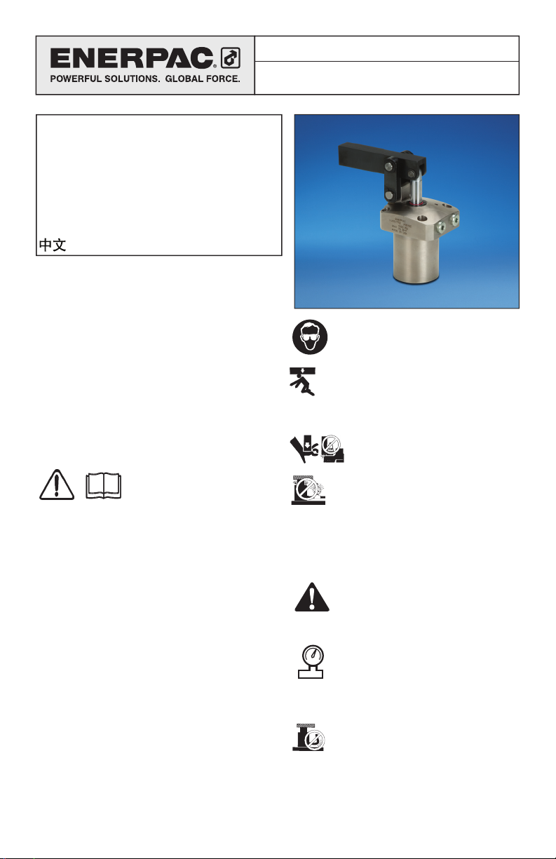
Instruction Sheet
70 Bar Link Clamp
WARNING: Wear proper personal
protective gear when operating hydraulic
equipment.
WARNING: Stay clear of loads supported
by hydraulics. A cylinder, when used as a
load lifting device, should never be used as
a load holding device. After the load has been raised
or lowered, it must always be blocked mechanically.
DANGER: To avoid personal injury
keep hands and feet away from cylinder
and workpiece during operation.
WARNING: Do not exceed equipment
ratings. Never attempt to lift a load
weighing more than the capacity of the
cylinder. Overloading causes equipment failure and
possible personal injury. The cylinders are designed
for a max. pressure of 350 bar [5,000 psi]. Do not
connect a jack or cylinder to a pump with a higher
pressure rating.
DANGER: Never set the relief valve to a
higher pressure than the maximum rated
pressure of the pump. Higher settings
may result in equipment damage and/or personal
injury. Do not remove relief valve.
WARNING: The system operating
pressure must not exceed the pressure
rating of the lowest rated component in
the system. Install pressure gauges in the
system to monitor operating pressure. It is your
window to what is happening in the system.
CAUTION: Avoid damaging hydraulic
hose. Avoid sharp bends and kinks when
routing hydraulic hoses. Using a bent or
kinked hose will cause severe back-pressure. Sharp
bends and kinks will internally damage the hose
leading to premature hose failure.
Page 2
Do not drop heavy objects on hose. A
sharp impact may cause internal damage
®
to hose wire strands. Applying pressure to
a damaged hose may cause it to rupture.
IMPORTANT: Do not lift hydraulic
equipment by the hoses or swivel
couplers. Use the carrying handle or other
means of safe transport.
CAUTION: Keep hydraulic equipment
away from flames and heat. Excessive
heat will soften packings and seals,
resulting in fluid leaks. Heat also weakens hose
materials and packings. For optimum performance
do not expose equipment to temperatures of 65 °C
[150 °F] or higher. Protect hoses and cylinders from
weld spatter.
DANGER: Do not handle pressurized
hoses. Escaping oil under pressure can
penetrate the skin, causing serious injury.
If oil is injected under the skin, see a doctor
immediately.
WARNING: Only use hydraulic cylinders in
a coupled system. Never use a cylinder
with unconnected couplers. If the cylinder
becomes extremely overloaded, components ca n fail
catastrophically causing severe personal injury.
IMPORTANT: Hydraulic equipment must
only be serviced by a qualified hydraulic
technician. For repair service, contact the
Authorized ENERPAC Service Center in your area. To
protect your warranty, use only ENERPAC oil.
WARNING: Immediately replace worn or
damaged parts with genuine ENERPAC
parts. Standard grade parts will break
causing personal injury and property damage.
ENERPAC parts are designed to fit properly and
withstand high loads.
3.0 INSTALLATION
The Enerpac 70 bar link clamp features an upper
flange design. The clamp can be mounted to the
fixture using the supplied mounting bolts. Oil can be
supplied to the clamp using either the BSPP hydraulic
ports on the flange or via the O-ring manifold ports
on the underside of the flange. The following sections
of this manual include detailed mounting instructions
that should be reviewed before attempting to install
the clamp on the fixture.
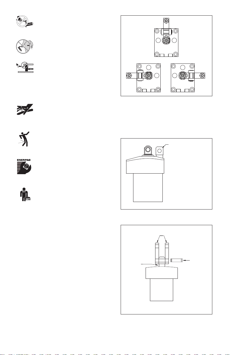
Center
Left Right
Figure 1
To install the linkage components, line up the two (2)
links with the hole in the anchor lug. Insert one (1) of
the long pivot pins through the links and the anchor
lug. Secure the pivot pin in place using two (2) of the
supplied E-clips (See Figures 2 and 3).
Hole in anchor
post must line up
perpendicular to
direction of clamp
arm.
Figure 2
Links
Anchor
Post
Pivot Pin
(long)
3.1 Clamp Arm Location
The Enerpac 70 bar link clamp contains an anchor
lug that is integral to the body. Models are available
that place this lug at a center, right or left position in
relation to the hydraulic ports (See Figure 1).
Figure 3
2
Page 3
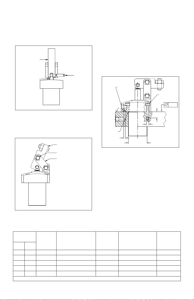
3.2 Arm Attachment
Place the clamp arm over the plunger end, lining up
the pivot pin holes. The clamp arm should extend
between the two links previously installed. Insert
the supplied short pivot pin through the arm and the
plunger, securing the parts together with the supplied
E-clips (See Figure 4).
3.3 Cylinder Mounting
The Enerpac 70 bar link clamp features a 4 bolt
flange style body for mounting the cylinder to the
fixture plate. Mounting bolts of the proper size and
length are supplied. Flange mounting requires the
machining of a through hole in the fixture plate or
mounting block and threads for the four (4) mounting
bolts. (See Figure 6 and Table 1).
Align the cylinder in the proper orientation to provide
Clamp Arm
clamping force to the part. Then, install the mounting
bolts and tighten per the value shown in Table 1.
Failure to properly tighten the mounting bolts can
result in damage to the cylinder and premature failure
of the clamp.
Plunger
Pivot Pin
(short)
Figure 4
Then, insert the second long pivot pin through the
top holes on the links and through the top hole on
the clamp arm, securing it with the last two supplied
E-clips (See Figure 5).
.5mm x 45°
Clamp Arm
Pivot Pin (long)
Link
3.4 Oil Connections
The cylinder can be plumbed using either the
hydraulic ports on the side of the flange, or the
manifold O-ring ports on the underside of the flange.
When using the manifold O-ring ports, use a 4.8 mm
diameter feed passage. The feed passage should
align with the center of the O-ring.
Hydraulic Fittings
The Enerpac 70 bar link clamp is supplied with BSPP
ports in the side of the flange. Connect the oil supply
to these ports using fittings rated for a minimum of
70 bar [1000 psi] only. Single acting (spring return)
Figure 5
models are vented. The supplied vent fitting may be
removed if using the manifold port for the vented
port.
Table 1 - Specifications
Clamp
Force
kN lbs.
2 450
3.5
5
7
9
1) At rated clamp point. 2) O-rings and mounting bolts are included.
1)
787
1124
1574
2023
Mounting
Hole
Ø D3
mm
Mounting Bolt
Thread
J
Min. Depth
J2
mm
36.5 M5 x .08 x 30 mm long 12 568-010 8.0-9.0
42.5 M5 x .08 x 30 mm long 12 568-010 8.0-9.0
48.5 M6 x 1.0 x 30 mm long 16 568-011 13.5-15.0
54.5 M6 x 1.0 x 30 mm long 16 568-011 13.5-15.0
60.5 M8 x 1.25 x 30 mm long 18 568-011 32.0-38.0
3
Manifold
O-Rings
(included)
63
ø 4,8
Manifold O-ring
øD3
Mtg. Hole
Figure 6
ARP No.
J2
J
2)
Mounting Bolts
(included)
0.004
Lubricated
Bolt Torque
Nm
Page 4

Double-acting cylinders require two ports to operate.
The port marked “A” should be connected to the
clamp line of the circuit. The port marked “B” should
be connected to the unclamp side of the circuit.
Make sure that fittings, hoses and tubing used are
rated at 70 bar [1000 psi] minimum working pressure.
Manifold Ports
Enerpac link clamps can also be plumbed using
the manifold ports on the underside of the flange.
The clamp is supplied from the factory with a small
cap screw and copper gasket installed in each port.
(Figure 7). Remove these items before installation.
The manifold ports require the use of O-rings as
face seals between the cylinder flange and the
fixture plate. These O-rings are supplied with the
clamp, typically in a small plastic bag along with the
mounting bolts and the documentation. Install these
O-rings (only one O-ring required for single acting
cylinders) into the seal grooves on the underside of
the mounting flange (See Figure 7).
Note: Before installation, the O-rings should be
coated with a small amount of hydraulic oil to prevent
damage during operation.
After installing O-rings, install the clamp as described
in section 3.3 (See Figure 6).
Upper Flange
4.0 OPERATION
Enerpac link clamps operate on hydraulic pressure
from 10 to 70 bar. The oil pressure is supplied via an
external pump plumbed through a circuit of valves
to the link clamps and other clamping elements on
the fixture. Single acting cylinders only require one
hydraulic line to provide clamping force, and use
an internal spring to retract the clamp arm when
pressure is removed. Double acting cylinders require
two hydraulic lines; one line provides pressure to
advance the arm and clamp the part; the other line
provides pressure to push the arm back and unclamp
the part. Either manual, air or electrically operated
valves are used to direct oil to one port or another.
5.0 MAINTENANCE
1. Use only Enerpac oil with this product. The use of
any other oil may invalidate your warranty.
2. Dynamic hydraulic seals need periodic
replacement due to normal wear and tear. A
regularly scheduled maintenance inspection plan
will help prevent unnecessary interruptions in
production due to seal wear.
3. The clamp linkage can be damaged or broken due
to mis-loaded parts or excessive contamination
build up. Any clips or pins that appear damaged
or worn should be replaced immediately.
4. All maintenance should be done by a qualified
hydraulic service technician. Enerpac has a global
service center network that can provide repair
and maintenance services if needed.
Remove port
screw plug.
O-ring
Figure 7
4
Page 5

6.0 TROUBLESHOOTING GUIDE
Allow only qualified hydraulic technicians to service the link clamp or system components. A system failure
may or may not be the result of a link clamp malfunction. To determine the cause of the problem, the complete
system must be included in any diagnostic procedure.
The information in the following chart is intended to be used only as an aid in determining if a problem exists.
For repair service, contact your local Authorized Enerpac Service Center.
PROBLEM POSSIBLE CAUSE/SOLUTION
Cylinder plunger will not
advance.
Cylinder advances in spurts.
Cylinder advances but does not
hold pressure or provide clamp
force.
Cylinder leaks oil.
Cylinder will not retract or
retracts slowly.
Control valve not open or damaged.
Couplers or fittings not properly connected.
Pump is not developing flow or pressure.
Linkage is not attached properly.
Linkage is bound by either misalignment or built up contamination.
Control valve not open or damaged.
Couplers or fittings not properly connected.
Pump is malfunctioning.
Linkage is bound by either misalignment or built up contamination.
Air in hydraulic system.
Control valve damaged.
Couplers or fittings leaking.
Pump is malfunctioning.
Internal seals are damaged and need replacement.
Cylinder bore or plunger are damaged and need replacement.
Clamp arm is not properly contacting part. Adjust contact bolt.
Internal seals are damaged and need replacement.
Cylinder bore or plunger are damaged and need replacement.
If cylinder is manifold mounted, O-rings could be damaged or
pinched and need replacement.
Control valve not open or damaged.
Couplers or fittings not properly connected.
Pump is malfunctioning.
Linkage is bound by either misalignment or built up contamination.
Air in hydraulic system.
Restrictions in return line. Check all installed accessories such as
filters for proper operation.
5
Page 6

Notes:
Page 7

Notes:
Page 8

A
A
A
A
A
Enerpac Worldwide Locations e-mail: info@enerpac.com internet: www.enerpac.com
ustralia and New Zealand
ctuant Australia Ltd.
Block V Unit 3
Regents Park Estate
391 Park Road
Regents Park NSW 2143
(P.O. Box 261) Australia
T +61 297 438 988
F +61 297 438 648
sales-au@enerpac.com
Brazil
Power Packer do Brasil Ltda.
Rua dos Inocentes, 587
04764-050 - Sao Paulo (SP)
T +55 11 5687 2211
F +55 11 5686 5583
Toll Free: 0800 891 5770
vendasbrasil@enerpac.com
Canada
ctuant Canada Corporation
6615 Ordan Drive, Unit 14-15
Mississauga, Ontario L5T 1X2
T +1 905 564 5749
F +1 905 564 0305
Toll Free:
T +1 800 268 4987
F +1 800 461 2456
customer.service@actuant.com
China (Taicang)
ctuant (China) Industries Co. Ltd.
No. 6 Nanjing Road,
Taicang Economic Dep Zone
Jiangsu, China
T +86 0512 5328 7500
F +86 0512 5335 9690
sales-cn@enerpac.com
China (Beijing)
ctuant (China) Industries Co. Ltd.
709B Diyang Building
Xin No. 2, Dong San Huan North Rd.
Beijing City, 100028 China
T +86 10 845 36166
F +86 10 845 36220
sales-cn@enerpac.com
France, Switzerland, North Africa and
French speaking African countries
ENERPAC
Une division d’ACTUANT France S.A.S.
ZA de Courtaboeuf
32, avenue de la Baltique
91140 VILLEBON /YVETTE
France
T +33 1 60 13 68 68
F +33 1 69 20 37 50
sales-fr@enerpac.com
Germany and Austria
ENERPAC GmbH
P.O. Box 300113
D-40401 Düsseldorf
Willstätterstrasse 13
D-40549 Düsseldorf, Germany
T +49 211 471 490
F +49 211 471 49 28
sales-de@enerpac.com
India
ENERPAC Hydraulics Pvt. Ltd.
No. 1A, Peenya Industrial Area
IInd Phase, Bangalore, 560 058, India
T +91 80 40 792 777
F +91 80 40 792 792
sales-in@enerpac.com
Italy
ENERPAC S.p.A.
Via Canova 4
20094 Corsico (Milano)
T +39 02 4861 111
F +39 02 4860 1288
sales-it@enerpac.com
Japan
Applied Power Japan LTD KK
Besshocho 85-7
Kita-ku, Saitama-shi 331-0821, Japan
T +81 48 662 4911
F +81 48 662 4955
sales-jp@enerpac.com
Middle East, Egypt and Libya
ENERPAC Middle East FZE
Office 423, LOB 15
P.O. Box 18004, Jebel Ali, Dubai
United Arab Emirates
T +971 (0)4 8872686
F +971 (0)4 8872687
sales-ua@enerpac.com
Russia
Rep. office Enerpac
Russian Federation
Admirala Makarova Street 8
125212 Moscow, Russia
T +7 495 98090 91
F +7 495 98090 92
sales-ru@enerpac.com
Singapore
Actuant Asia Pte Ltd.
83 Joo Koon Circle
Singapore 629109
T +65 68 63 0611
F +65 64 84 5669
Toll Free: +1800 363 7722
sales-sg@enerpac.com
South Korea
Actuant Korea Ltd.
3Ba 717, Shihwa Industrial Complex
Jungwang-Dong, Shihung-Shi,
Kyunggi-Do
Republic of Korea 429-450
T +82 31 434 4506
F +82 31 434 4507
sales-kr@enerpac.com
Spain and Portugal
ENERPAC SPAIN, S.L.
Avda. Los Frailes, 40 – Nave C & D
Pol. Ind. Los Frailes
28814 Daganzo de Arriba
(Madrid) Spain
T +34 91 884 86 06
F +34 91 884 86 11
sales-es@enerpac.com
Sweden, Denmark, Norway, Finland
and Iceland
Enerpac Scandinavia AB
Fabriksgatan 7
412 50 Gothenburg
Sweden
T +46 (0) 31 799 0281
F +46 (0) 31 799 0010
scandinavianinquiries@enerpac.com
The Netherlands, Belgium,
Luxembourg,
Central and Eastern Europe,
Baltic States, Greece, Turkey
and CIS countries
ENERPAC B.V.
Galvanistraat 115
6716 AE Ede
P.O. Box 8097
6710 AB Ede
The Netherlands
T +31 318 535 800
F +31 318 535 848
sales-nl@enerpac.com
Enerpac Integrated Solutions B.V.
Opaalstraat 44
7554 TS Hengelo
P.O. Box 421
7550 AK Hengelo
The Netherlands
T +31 74 242 20 45
F +31 74 243 03 38
integratedsolutions@enerpac.com
South Africa and other English
speaking African countries
ENERPAC B.V.
Galvanistraat 115
6716 AE Ede
P.O. Box 8097
6710 AB Ede
The Netherlands
T +31 318 535 911
F +31 318 525 613
sales-za@enerpac.com
United Kingdom and Ireland
ENERPAC Ltd.,
Bentley Road South
Darlaston, West Midlands
WS10 8LQ
England
T +44 (0)121 50 50 787
F +44 (0)121 50 50 799
sales-uk@enerpac.com
USA, Latin America and Caribbean
ENERPAC
P.O. Box 3241
6100 N. Baker Road
Milwaukee
WI 53209 USA
T +1 262 781 6600
F +1 262 783 9562
User inquiries:
+1 800 433 2766
Distributor inquiries/orders:
+1 800 558 0530
sales-us@enerpac.com
01/25/11
 Loading...