

Instruction Sheet
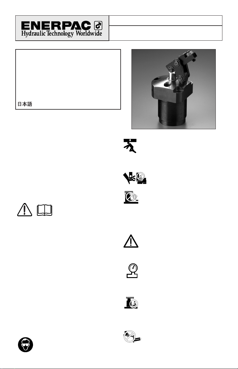
Link Clamp
Index:
English ...................................................................1-5
Français ............................................................... N/A
Deutsch............................................................... N/A
Italiano ................................................................ N/A
Español ............................................................... N/A
Nederlands ......................................................... N/A
Portuguese ......................................................... N/A
.............................................................
N/A
®
L2622 Rev A 10/04
Repair Parts Sheets for this product are available
from the Enerpac web site at www.enerpac.com, or
from your nearest Authorized Enerpac Service Center
or Enerpac Sales office.
1.0 IMPORTANT RECEIVING
INSTRUCTIONS
Visually inspect all components for shipping damage.
Shipping damage is not covered by warranty. If
shipping damage is found, notify carrier at once. The
carrier is responsible for all repair and replacement
costs resulting from damage in shipment.
SAFETY FIRST
2.0 SAFETY ISSUES
Read all instructions, warnings
and cautions carefully. Follow all
safety precautions to avoid
personal injury or property damage during system
operation. Enerpac cannot be responsible for damage
or injury resulting from unsafe product use, lack of
maintenance or incorrect product and/or system
operation. Contact Enerpac when in doubt as to the
safety precautions and operations. If you have never
been trained on high-pressure hydraulic safety,
consult your distribution or service center for a free
Enerpac Hydraulic safety course.
Failure to comply with the following cautions and
warnings could cause equipment damage and
personal injury.
A CAUTION is used to indicate correct operating or
maintenance procedures and practices to prevent
damage to, or destruction of equipment or other
property.
A WARNING indicates a potential danger that
requires correct procedures or practices to avoid
personal injury.
A DANGER is only used when your action or lack of
action may cause serious injury or even death.
WARNING: Wear proper personal
protective gear when operating hydraulic
equipment.
WARNING: Stay clear of loads
supported by hydraulics. A cylinder,
when used as a load lifting device, should
never be used as a load holding device.
After the load has been raised or lowered, it must
always be blocked mechanically.
DANGER: To avoid personal injury keep
hands and feet away from cylinder and
workpiece during operation.
WARNING: Do not exceed equipment
ratings. Never attempt to lift a load
weighing more than the capacity of the
cylinder. Overloading causes equipment failure and
possible personal injury. The cylinders are designed
for a max. pressure of 350 bar [5,000 psi]. Do not
connect a jack or cylinder to a pump with a higher
pressure rating.
DANGER: Never set the relief valve to a
higher pressure than the maximum rated
pressure of the pump. Higher settings may
result in equipment damage and/or personal injury.
Do not remove relief valve.
WARNING: The system operating
pressure must not exceed the pressure
rating of the lowest rated component in
the system. Install pressure gauges in the
system to monitor operating pressure. It is your
window to what is happening in the system.
CAUTION: Avoid damaging hydraulic
hose. Avoid sharp bends and kinks when
routing hydraulic hoses. Using a bent or
kinked hose will cause severe back-pressure. Sharp
bends and kinks will internally damage the hose
leading to premature hose failure.
Do not drop heavy objects on hose. A
sharp impact may cause internal damage
to hose wire strands. Applying pressure to
a damaged hose may cause it to rupture.
®
2
IMPORTANT: Do not lift hydraulic
equipment by the hoses or swivel
couplers. Use the carrying handle or other
means of safe transport.
CAUTION: Keep hydraulic equipment
away from flames and heat. Excessive
heat will soften packings and seals,
resulting in fluid leaks. Heat also weakens
hose materials and packings. For optimum
performance do not expose equipment to
temperatures of 65 °C [150 °F] or higher. Protect
hoses and cylinders from weld spatter.
DANGER: Do not handle pressurized
hoses. Escaping oil under pressure can
penetrate the skin, causing serious injury.
If oil is injected under the skin, see a doctor
immediately.
WARNING: Only use hydraulic cylinders in
a coupled system. Never use a cylinder
with unconnected couplers. If the cylinder
becomes extremely overloaded, components
can fail catastrophically causing severe personal injury.
IMPORTANT: Hydraulic equipment must
only be serviced by a qualified hydraulic
technician. For repair service, contact the
Authorized ENERPAC Service Center in
your area. To protect your warranty, use only
ENERPAC oil.
WARNING: Immediately replace worn or
damaged parts by genuine ENERPAC parts.
Standard grade parts will break causing
personal injury and property damage. ENERPAC parts
are designed to fit properly and withstand high loads.
3.0 INSTALLATION
The Enerpac link clamp can be installed with the
clamp arm in one of three different locations. The
clamps can be mounted to the fixture using either the
threaded body or the supplied mounting bolts. Oil
can be supplied to the clamp using either the
threaded hydraulic ports on the flange or via the Oring ports on the underside of the flange. The
sections that follow provide detailed mounting
instructions and should be reviewed before
attempting to install the clamps on the fixture.
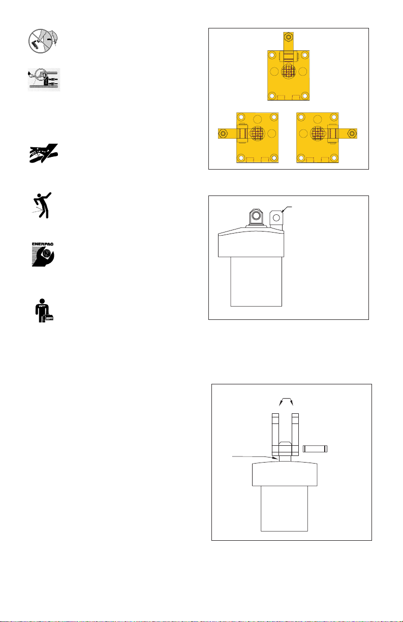
3.1 Clamp Arm Location
The arm and linkage can be positioned in any of three
different positions as shown in Figure 1 below. The
anchor post threads into the top flange of the cylinder
in any of the three threaded holes. Thread the anchor
post into the flange until it bottoms out, then turn the
post back up to 1/2 turn in order to line up the pivot
pin hole perpendicular to the desired clamp direction
(Figure 2). Make sure that the hole in the plunger is
lined up parallel to the hole in the anchor post.
Figure 1
Figure 2
Line up the two (2) links with the hole in the anchor
post. Insert one (1) of the long pivot pins through the
links and the anchor post. Secure the pivot pin in
place using two (2) of the supplied E-clips (Figure 3).
Figure 3
Center
Hole in anchor post
must line up
perpendicular to
direction of clamp
arm.
Anchor post
Pivot pin
Links
Left Right

3.2 Arm Attachment
Place the clamp arm over the plunger end, lining up
the pivot pin holes. The clamp arm should extend
between the two links previously installed. Insert the
supplied short pivot pin through the arm and the
plunger, securing the parts together with the supplied
E-clips (Figure 4).
Figure 4
Then, insert the second long pivot pin through the
top holes on the links and through the top hole on the
clamp arm, securing it with the last two supplied
E-clips (Figure 5).
Figure 5
3.3 Mountings
Cylinder Mounting
Enerpac link clamps can be mounted using either the
top flange and the supplied mounting bolts; or
through the use of the body thread on the cylinder
and a jam nut.
Note: mounting the cylinders using the body threads
prevents plumbing the cylinders through the manifold
ports on the underside of the flange. The only way to
utilize this plumbing method is to flange mount the
cylinder.
Flange Mounting
Flange mounting requires the machining of a thruhole in the fixture plate or mounting block and
mounting threads for the four bolts (Figure 6).
See Table 1 below.
Align the cylinder in the proper orientation to provide
clamping force to the part and then install the
mounting bolts and tighten per the chart below.
Failure to tighten the mounting bolts properly can
result in damage to the cylinder and premature failure
of the clamp.
Threaded Body Mounting
Mounting the cylinder using the body threads
requires a clearance hole machined in the fixture
plate and the installation of a jam nut to secure the
cylinder in
place. The
clearance
hole should
be sized
according to
the
dimensions
in Figure 6.
The fixture
plate can
also be
machined to
matching
internal
threads as
long as the
3
Figure 6
Pull
1)
Fixture Mounting Min. Manifold O-ring
2)
force hole thread depth ARP No. or
lbs Ø D3 J UNF J2 Inside Ø x thickness
700
1.885 .250-28 0.65 -010
1800
2.510 .312-24 0.75 -010
2700
3.135 .312-24 0.75 -010
4300
3.515 .375-24 0.88 -010
6300
4.140 .500-20 0.94 -010
1)
With standard clamp arm.
2)
Polyurethane, 92 Durometer
Note: Mounting bolts and
O-rings included.
Manifold
O-ring
Table 1
Clamp arm
Clamp arm
Pivot pin
Pivot pin
Link
Plunger
63
[1,6]
D3
ø .19 [4,8]
J2
J
.004
0,1

plate is designed to withstand full clamping capacity.
A jam nut is still required in this case to maintain the
clamping orientation. The jam nut should be installed
on the inside of the fixture plate for most secure
mounting.
3.4 Oil Connection
The cylinder can be plumbed using either the
hydraulic ports on the side of the flange, or the
manifold O-ring ports on the underside of the flange.
The manifold ports can only be used when the
cylinder is flange mounted using the four mounting
bolts as shown in Figure 6.
Hydraulic Fittings
Enerpac link clamps are supplied with either SAE Oring ports or BSPP ports in the side of the flange.
Single acting cylinders require only one hydraulic
port. Unlike many other cylinders, single acting
Enerpac link clamps do not require the use of a vent
port. Connect the oil supply to this port using fittings
rated for a minimum of 5000 psi (350 bar) only.
Double-acting cylinders require two ports to operate.
The port marked “A” should be connected to the
clamp line of the circuit. The port marked “B” should
be connected to the unclamp side of the circuit.
Again, be sure to use fittings and tubing rated for a
minimum of 5000 psi (350 bar) working pressure.
Manifold ports
Enerpac link clamps can also be plumbed using the
manifold ports on the underside of the flange. The
clamps are supplied from the factory with small cap
screw and copper gasket installed in these ports
(Figure 7). Remove these items before installation.
The manifold ports require the use of O-rings as face
seals between the cylinder flange and the fixture
plate. These O-rings are supplied with the clamp,
typically in a small plastic bag along with the
mounting bolts and the documentation. Install these
O-rings (only one O-ring required for single acting
cylinders) into the seal grooves on the underside of
the mounting flange (Figure 7).
Before installation, the O-rings should be coated with
a small amount of hydraulic oil to prevent damage
during operation. Mount the clamps using the
installation instructions in section 3.3. Remember
that the cylinders must be flange mounted when
using the manifold porting method.
Figure 7
4.0 OPERATION
Enerpac link clamps operate on hydraulic pressure
from 500 to 5000 psi (35-350 bar). This oil pressure is
supplied via an external pump plumbed through a
circuit of valves to the link clamps and other clamping
elements on the fixture. Single acting cylinders only
require one hydraulic line to provide clamping force,
and use an internal spring to retract the clamp arm
when pressure is removed. Double acting cylinders
require two hydraulic lines; one line provides pressure
to advance the arm and clamp the part; the other line
provides pressure to push the arm back and unclamp
the part. Either manual, air or electrically operated
valves are used to direct oil to one port or another.
5.0 MAINTENANCE
1. Use only Enerpac oil with these cylinders. The use
of any other oil may invalidate your warranty.
2. Dynamic hydraulic seals need periodic
replacement due to normal wear and tear. A
regularly scheduled maintenance inspection plan
will help prevent unnecessary interruptions in
production due to seal wear.
3. The clamp linkage can be damaged or broken due
to mis-loaded parts or excessive contamination
build up. Any clips or pins that appear damaged
or worn should be replaced immediately.
4. All maintenance should be done by a qualified
hydraulic service technician. Enerpac has a global
service center network that can provide repair and
maintenance services if needed.
4
Remove port
screw plug.
Lower flange
Upper flange
O-ring
O-ring
Remove port
screw plug.

5
PROBLEM POSSIBLE CAUSE/SOLUTION
Control valve not open or damaged.
Couplers or fittings not properly connected.
Pump is not developing flow or pressure.
Linkage is not attached properly.
Linkage is bound by either misalignment or built up contamination.
Control valve not open or damaged.
Couplers or fittings not properly connected.
Pump is malfunctioning.
Linkage is bound by either misalignment or built up contamination.
Air in hydraulic system.
Control valve damaged.
Couplers or fittings leaking.
Pump is malfunctioning.
Internal seals are damaged and need replacement.
Cylinder bore or plunger are damaged and need replacement.
Clamp arm is not properly contacting part. Adjust contact screw.
Internal seals are damaged and need replacement.
Cylinder bore or plunger are damaged and need replacement.
If cylinder is manifold mounted, O-rings could be damaged or
pinched and need replacement.
Control valve not open or damaged.
Couplers or fittings not properly connected.
Pump is malfunctioning.
Linkage is bound by either misalignment or built up contamination.
Air in hydraulic system.
Restrictions in return line. Check all installed accessories such as
filters for proper operation.
Cylinder plunger will not
advance.
Cylinder advances in spurts.
Cylinder advances but does
not hold pressure or provide
clamp force.
Cylinder leaks oil.
Cylinder will not retract or
retracts slowly.
6.0 TROUBLE-SHOOTING GUIDE

Enerpac Worldwide Locations ✦
Africa
ENERPAC Middle East FZE
P. O. Box 18004
Jebel Ali, Dubai
United Arab Emirates
Tel: +971 (0)4 8872686
Fax: +971 (0)4 8872687
Australia
ENERPAC, Actuant Australia Ltd.
Block V Unit 3
Regents Park Estate
391 Park Road
Regents Park NSW 2143
(P.O. Box 261) Australia
Tel: +61 297 438 988
Fax: +61 297 438 648
Brazil
Power Packer do Brasil Ltda.
Rua dos Inocentes, 587
04764-050 - Sao Paulo (SP)
Tel: +55 11 5687 2211
Fax: +55 11 5686 5583
Toll Free in Brazil:
Tel: 0800 891 5770
vendasbrasil@enerpac.com
Canada
Actuant Canada Corporation
6615 Ordan Drive, Unit 14-15
Mississauga, Ontario L5T 1X2
Tel: +1 905 564 5749
Fax: +1 905 564 0305
Toll Free:
Tel: +1 800 268 4987
Fax: +1 800 461 2456
Technical Inquiries:
techservices@enerpac.com
China
Actuant China Ltd.
1F, 269 Fute N. Road
Waigaoqiao Free Trade Zone
Pudong New District
Shanghai, 200 131 China
Tel: +86 21 5866 9099
Fax: +86 21 5866 7156
Actuant China Ltd. (Beijing)
709A Xin No. 2
Diyang Building
Dong San Huan North Rd.
Beijing City, 100028 China
Tel: +86 10 845 36166
Fax: +86 10 845 36220
Central and Eastern Europe
ENERPAC B.V.
Storkstraat 25
P. O. Box 269, 3900 AG Veenendaal
The Netherlands
Tel: +31 318 535 936
Fax: +31 318 535 951
France
ENERPAC
Une division de ACTUANT s.a.
B.P. 200
Parc d’Activités
du Moulin de Massy
F-91882 Massy CEDEX France
Tel: +33 1 601 368 68
Fax: +33 1 692 037 50
Germany, Austria, Szwitzerland, Russia,
Greence and CIS (excl. Caspian Sea
Countries) ENERPAC Applied Power
GmbH
P. O. Box 300113
D-40401 Düsseldorf
Germany
Tel: +49 211 471 490
Fax: +49 211 471 49 28
India
ENERPAC Hydraulics (India) Pvt. Ltd.
Plot No. A/571
MIDC, TTC Industrial Area
Mahape-400 701
Navi Mumbai, India
Tel: +91 22 2778 1472
Fax: +91 22 2778 1473
Italy
ENERPAC S.p.A.
Via Canova 4
20094 Corsico (Milano)
Tel: +39 02 4861 111
Fax: +39 02 4860 1288
Japan
Applied Power Japan Ltd.
1-1-11, Shimomae
Toda-shi, Saitama Pref.
Japan 335-0016
Tel: +81 484 30 1055
Fax: +81 484 30 1066
The Netherlands, Belgium, Luxembourg,
Sweden, Denmark, Norway, Finland,
Baltic States
ENERPAC B.V.
Storkstraat 25
P.O. Box 269
3900 AG Veenendaal
The Netherlands
Tel: +31 318 535 911
Fax: +31 318 525 613
Technical Inquiries Europe:
techsupport.europe@enerpac.com
All Enerpac products are guaranteed against defects in workmanship
and materials for as long as you own them. For your nearest
authorized Enerpac Service Center, visit us at www.enerpac.com
e-mail: info@enerpac.com
+31 318 535 848
✦
internet: www.enerpac.com
Singapore
Enerpac Asia Pte. Ltd.
25 Serangoon North Ave. 5
#03-01 Keppel Digihub
Singapore 554914
Thomson Road, P.O. Box 114
Singapore 915704
Tel: +65 64 84 5108
+65 64 84 3737
1800 363 7722
Fax: +65 64 84 5669
Technical Inquiries:
sales@enerpac.com.sg
South Korea
Actuant Korea Ltd.
3Ba 717, Shihwa Industrial Complex,
Jungwang-Dong, Shihung-Shi, Kyunggi-Do
Republic of Korea 429-450
Tel: +82 31 434 4506
Fax: +82 31 434 4507
Spain, Portugal
ENERPAC
C/San José Artesano 8 Pol. Ind.
28108 Alcobendas
(Madrid) Spain
Tel: +34 91 661 11 25
Fax: +34 91 661 47 89
Middle East, Turkey ,
Caspian Sea
ENERPAC Middle East FZE
P. O . Box 18004
Jebel Ali, Dubai
United Arab Emirates
Tel: +971 (0)4 8872686
Fax: +971 (0)4 8872687
United Kingdom, Ireland
ENERPAC Ltd., P.O. Box 33
New Romney, TN28 8QF
United Kingdom
44 01797 363 639
Tel: +
Fax: +44 01527 585 500
USA, Latin America
and Caribbean
ENERPAC
P. O. Box 3241
6100 N. Baker Road
Milwaukee, WI 53209 USA
Tel: +1 262 781 6600
Fax: +1 262 783 9562
User inquiries:
+1 800 433 2766
Distributor inquiries/orders:
+1 800 558 0530
Technical Inquiries:
techservices@enerpac.com
081904
 Loading...