

Page 1
1
POWERFUL SOLUTIONS. GLOBAL FORCE.
Instruction Sheet
High Tonnage Hydraulic Cylinders
HCRL-Series
L4247 Rev. A 03/18
Table of Contents:
Section Page
1.0 IMPORTANT RECEIVING INSTRUCTIONS ......1
2.0 SAFETY .................................1
3.0 CONFORMANCE TO NATIONAL AND
INTERNATIONAL STANDARDS ...............3
4.0 PRODUCT DESCRIPTION ...................3
5.0 LIFTING THE CYLINDER ....................4
6.0 SETUP ..................................4
7.0 AVOIDING SIDE LOAD ......................5
8.0 OPERATION ..............................5
9.0 INSPECTION, MAINTENANCE & STORAGE .....5
10.0 RELIEVING TRAPPED PRESSURE ...........5
11.0 TROUBLESHOOTING .....................6
12.0 PRODUCT DATA ..........................7
1.0 IMPORTANT RECEIVING INSTRUCTIONS
Visually inspect all components for shipping damage. Shipping
damage is not covered by warranty. If shipping damage is
found, notify carrier at once. The carrier is responsible for
all repair and replacement costs resulting from damage in
shipment.
2.0 SAFETY
2.1 Introduction
Read all instructions carefully. Follow all recommended safety
precautions to avoid personal injury as well as damage to the
product and/or damage to other property. Enerpac cannot be
responsible for any damage or injury from unsafe use, lack of
maintenance or incorrect operation. Do not remove warning
labels, tags, or decals. In the event any questions or concerns
arise, contact Enerpac or a local Enerpac distributor for
clarification.
If you have never been trained on high-pressure hydraulic
safety, consult your distributor or service center for information
about an Enerpac Hydraulic Safety Course.
This manual follows a system of safety alert symbols, signal
words and safety messages to warn the user of specific
hazards. Failure to comply with these warnings could result
in death or serious personal injury, as well as damage to the
equipment or other property.
The Safety Alert Symbol appears throughout this
manual. It is used to alert you to potential physical
injury hazards. Pay close attention to Safety Alert
Symbols and obey all safety messages that follow this symbol
to avoid the possibility of death or serious personal injury.
Safety Alert Symbols are used in conjunction with certain
Signal Words that call attention to safety messages or property
damage messages and designate a degree or level of hazard
seriousness. The Signal Words used in this manual are
WARNING, CAUTION and NOTICE.
WARNING
Indicates a hazardous situation that, if not
avoided, could result in death or serious
personal injury.
CAUTION
Indicates a hazardous situation that, if not
avoided, could result in minor or moderate
personal injury.
NOTICE
Indicates information considered important,
but not hazard related (e.g. messages
relating to property damage). Please note
that the Safety Alert Symbol will not be used
with this signal word.
2.2 Hydraulic Cylinder Safety Precautions
(HCRL-Series)
WARNING
Failure to observe and comply with the following
precautions could result in death or serious personal
injury. Property damage could also occur.
• Read and completely understand the safety precautions and
instructions in this manual before operating the cylinder or
preparing it for use. Always follow all safety precautions and
instructions, including those that are contained within the
procedures of this manual.
• Operating procedures will vary, depending on the system
arrangement and the specific components being used.
Always read, follow and completely understand all
manufacturer's instructions when operating pumps, valves
and all other devices used with the cylinders. Follow all
safety precautions contained in the manufacturer's manuals.
• Always wear appropriate personal protective equipment
(P.P.E.) when operating hydraulic equipment. Be sure to
wear eye protection, work gloves and protective clothing.
Page 2

2
Use of additional P.P.E. safety items such as dust mask,
non-skid safety shoes, hard hat, and hearing protection
(used as appropriate for the conditions) will reduce the
chance of personal injuries. The use of these items may also
be required by local regulations or laws.
• Do not handle pressurized hoses. Escaping oil under
pressure can penetrate the skin. If oil is injected under the
skin, see a doctor immediately.
• Do not pressurize disconnected couplers.
• Use hydraulic cylinders only in a coupled system. It is
acceptable to use a cylinder with a disconnected coupler
only if the load is mechanically supported by the cylinder
lock nut, and all hydraulic pressure is completely relieved.
• When holding loads, be certain that the lock nut is turned
down firmly against the cylinder base so that the load is
mechanically supported. Also be sure that all hydraulic
pressure is completely relieved.
• Do not remove or disable the pump relief valve.
• Do not remove or disable the cylinder relief valve (if equipped).
• The system operating pressure must not exceed the pressure
rating of the lowest rated component in the system.
• Install pressure gauge(s) in the system to monitor operating
pressure. It is your window to see what is happening in the system.
• Never set a relief valve to a higher pressure than the
maximum rated pressure of the pump and cylinder. If ratings
are dierent, relief valve setting should not exceed the
setting of the lowest rated component (pump or cylinder).
• The HCRL-Series cylinders are designed for a maximum
working pressure of 10150 psi [700 bar]. Do not connect a
pump with a higher pressure rating to these cylinders.
• Do not exceed equipment ratings. Never attempt to lift a
load weighing more than the rated capacity of the cylinder.
Overloading may cause equipment failure and possible
personal injury.
• Be sure setup is stable before lifting load. Cylinders should
be located on a firm and level surface capable of supporting
the full load.
• Where applicable, use a cylinder base plate to provide
added stability. If desired, the cylinder can be bolted to the
base plate, using the bolt holes in the bottom of the cylinder
base.
• Do not weld, drill or otherwise modify a cylinder to attach a
base plate or other support unless approved in writing by
Enerpac Engineering Department. Use only the provided
bolt holes.
• Always perform a visual inspection of the cylinder before
placing it into operation. If any problems are found, do not
use the cylinder. Have the cylinder repaired and tested
before it is returned to service.
• Never use a cylinder that is leaking oil. Do not use a cylinder
that is damaged, altered or in need of repair.
• Always lift the cylinder using a hoist, crane or other suitable
lifting device of sucient rated capacity. Use only the
supplied cylinder lifting eyes to attach the cylinder to the
lifting device. Replace any missing or damaged lifting eyes.
• Allow only trained and experienced personnel to supervise
and perform lifting and lowering procedures.
• Be certain that no persons are working on or near any
cylinders before lifting or lowering of the load begins. Alert all
personnel in advance that lifting or lowering is about to occur.
• Use suitable cribbing of rigid construction to hold loads.
• Never use a hydraulic cylinder as a shim or spacer in any
lifting or pressing application.
• Be certain that the load is centered and covers the entire
plunger saddle surface. Avoid situations where loads are not
directly centered on the plunger saddle. The load may slip or
fall, causing potential danger.
• Lift only dead weight loads. Avoid lifting live weight loads.
• Be especially careful when lifting loads such as partially filled
storage tanks, in which the center of gravity could move or
shift during lifting. Be aware that the distribution of some
loads can change quickly and without warning.
• Do not use the cylinder to lift people. Do not allow people to
be on top of the load during lifting or lowering.
• Keep all personnel clear of the work area while lifting or
lowering is in progress. To avoid personal injury, keep hands
and feet away from cylinder and load during operation.
• Maintain communication with the operator at all times during
lifting or lowering to avoid accidents. Use hand signals, twoway radios or other appropriate forms of communication (as
required by applicable laws and regulations) if the load is not
visible to the operator.
• Operate pump and valve as required to ensure that the load
is lifted and lowered evenly and at a controlled rate.
• Closely watch the load at all times during lifting and lowering.
Stop lifting or lowering immediately if the load becomes
unstable or appears to be lifting or lowering unevenly.
• Stay clear of loads supported only by hydraulics. As required,
follow the lifted load with cribbing.
• Never allow persons to work under or near the load while the
load is being supported hydraulically. After the load has been
raised or lowered, it always must be blocked mechanically
by the cylinder lock nut or via suitable cribbing.
• Always be certain that hydraulic pressure is fully relieved
and that the load is fully removed from the cylinder(s) before
disconnecting hydraulic hoses, loosening hydraulic fittings,
or performing any cylinder disassembly or repair procedures.
CAUTION
Failure to observe and comply with the following
precautions could result in minor or moderate personal
injury. Property damage could also occur.
• Be careful to avoid damaging hydraulic hoses. Avoid sharp
bends and kinks when routing hydraulic hoses. Do not
exceed the minimum bend radius specified by the hose
manufacturer. Using a bent or kinked hose will cause severe
back-pressure. Sharp bends and kinks will internally damage
the hose, leading to premature hose failure.
• Do not drop heavy objects on hoses. A sharp impact may
cause internal damage to hose wire strands. Applying
pressure to a damaged hose may cause it to rupture.
• Do not lift hydraulic equipment by the hoses or couplers.
Use the cylinder lifting eyes and appropriately rated lifting
equipment.
• Keep hydraulic equipment away from flames and heat.
Excessive heat will soften packings and seals, resulting in
fluid leaks. Heat also weakens hose materials and packings.
• For optimum performance, do not expose hydraulic
equipment to temperatures of 150˚F [65˚C] or higher. Protect
all hydraulic equipment from weld spatter.
• Immediately replace worn or damaged parts with genuine
Enerpac parts. Enerpac parts are designed to fit properly
and to withstand high loads. Non-Enerpac parts may break
or cause the product to malfunction.
NOTICE
• Hydraulic equipment must only be serviced by a qualified
hydraulic technician. For repair service, contact the Enerpac
Authorized Service Center in your area.
• To help ensure proper operation and best performance, use
of Enerpac oil is strongly recommended.
Page 3
3
1
8
2
5
4
6
7
9
10
3
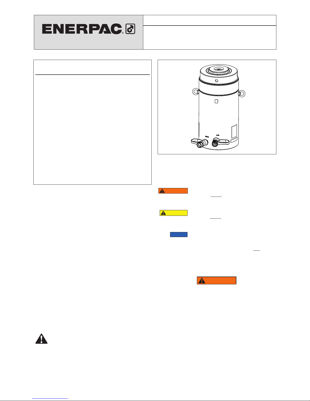
Key:
1. Tilt Saddle
2. Plunger
3. Lock Nut
4. Collar Threads
5. Cylinder Base
6. Safety Relief Valve
7. Hydraulic Coupler (advance)
3/8"-18 NPTF
8. Hydraulic Coupler (retract)
3/8"-18 NPTF
9. Lifting Eye
10. Stop Ring
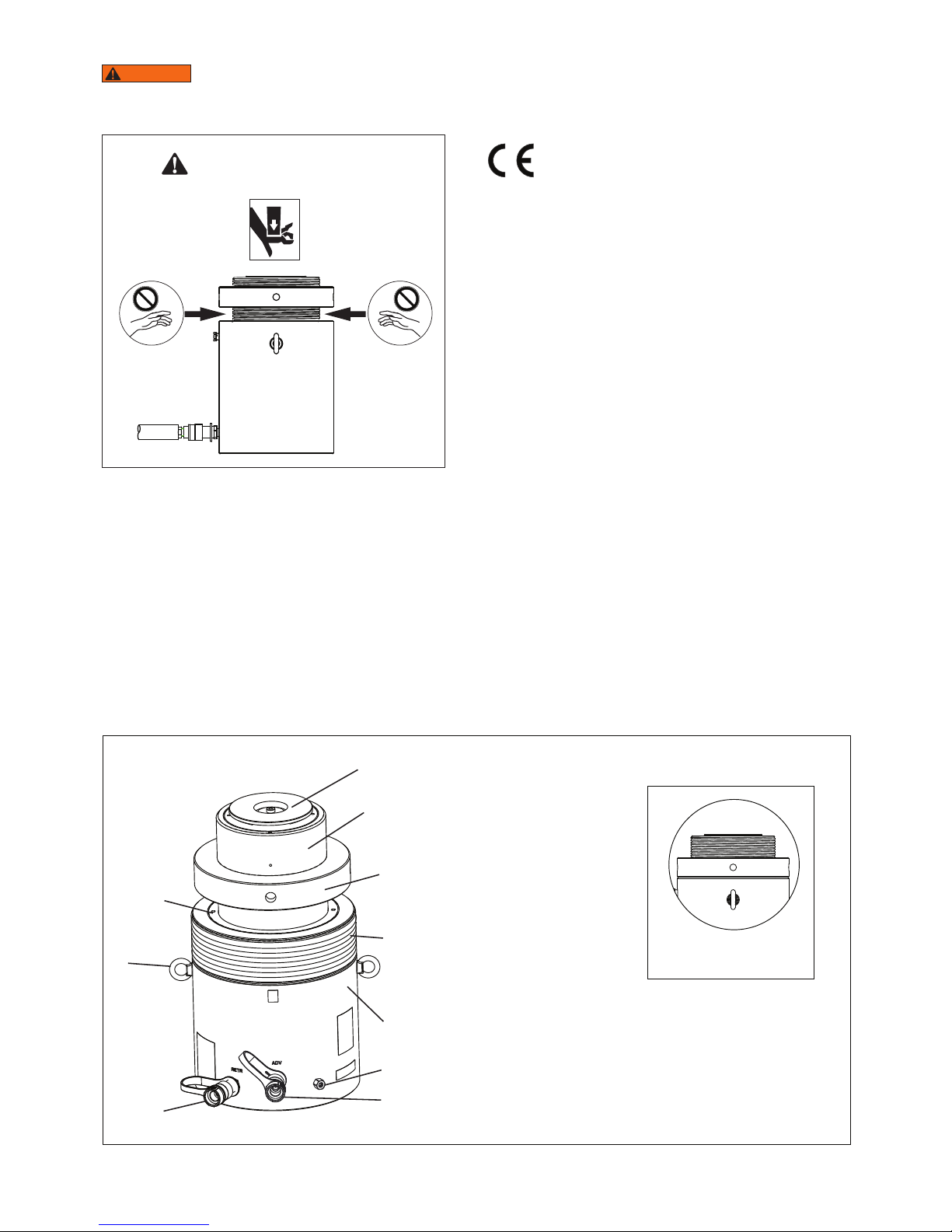
2.3 Crush and Pinch Point Hazard (HCRL-Series)
WARNING
Never reach in between the cylinder lock
nut and the top of the cylinder base. Serious personal
injury can occur if cylinder is retracted and hands, fingers
or other body parts are present in this area. See Figure 1.
CRUSH AND PINCH POINT HAZARD
Do not reach in between lock nut
and cylinder base!
Figure 1, Crush and Pinch Point Hazard
2.4 Additional Safety References
Consult the applicable industry and/or government standards
in your country or region for additional safety precautions and
work rules applicable to hydraulic cylinders, jacks and other
similar lifting equipment.
In the USA, refer to the following publications:
• Code of Federal Regulations - Title 29 Occupational Safety
and Health Standards (U.S. Government Publishing Oce,
732 North Capitol Street, NW, Washington, DC 20401-0001.
www.gpo.gov).
• ASME B30.1 Standards - Jacks (American Society of
Mechanical Engineers, Two Park Avenue, New York, NY
10016-5990. www.asme.org).
In the European Union, refer to the standards and directives
listed in the product's EU Declaration of Incorporation. A copy
of this document is packed separately with the cylinder.
3.0 CONFORMANCE TO NATIONAL AND
INTERNATIONAL STANDARDS
Enerpac declares that this product has been tested
and conforms to applicable standards and is
compatible to all CE Requirements. A copy of an EU
Declaration of Incorporation is enclosed with each shipment of
this product.
4.0 PRODUCT DESCRIPTION
Enerpac HCRL-Series cylinders are an ideal solution for a wide
variety of commercial and industrial lifting applications.
HCRL-Series cylinders are double-acting with hydraulic
advance and return. A lock nut provides mechanical load
holding capabilities.
The hydraulic return feature allows greater control during
lowering and provides positive retraction of the plunger. Note
that the HCRL-Series cylinders are not designed for pulling
applications.
Capacities range from 62 to 1196 US tons [550 to 10644 kN].
Refer to the product data markings on the cylinder base for the
capacity rating of your cylinder model.
All standard production HCRL-Series cylinders are designed
for 10150 psi [700 bar] maximum working pressure.
An integrated tilt saddle is standard equipment on all models.
Refer to Section 12 of this manual for cylinder weights, oil
volumes, dimensions and additional specifications.
Figure 2, Major Features and Components
LOCK NUT TIGHTENED
(Mechanical Load Holding)
Page 4
4
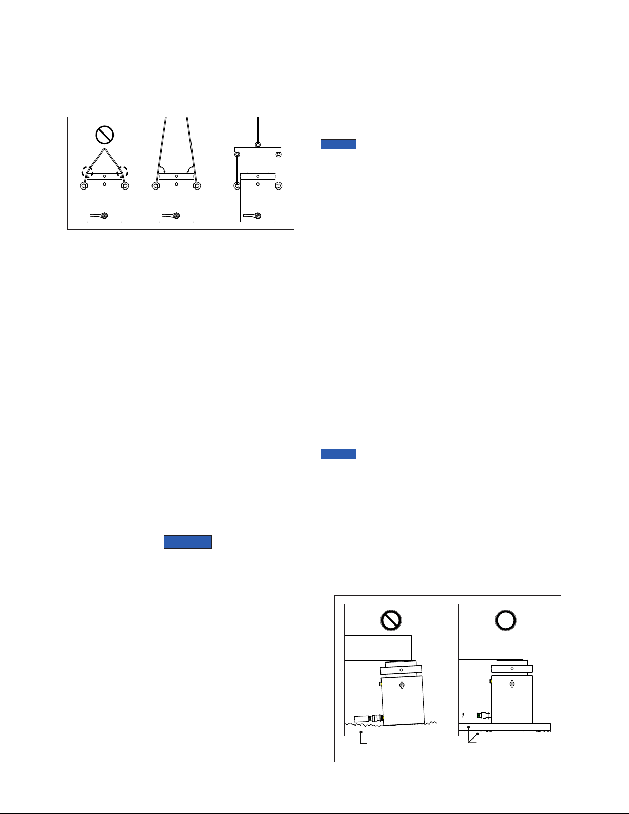
5.0 LIFTING THE CYLINDER
All HCRL-Series cylinders are equipped with TWO pre-installed
lifting eyes. Always use both lifting eyes when hoisting the
cylinder.
Lifting straps or chains must be positioned at an angle where
they will not interfere with the cylinder base. Use of a spreader
bar is recommended. See Figure 3.
Figure 3, Lifting Arrangements (typical)
OK
OK
6.0 SETUP
6.1 Hydraulic Pump Requirements
Hydraulic pumps are sold separately and are not included with
the cylinders.
A hand-operated hydraulic pump can be used to operate a
smaller HCRL-Series cylinder. However, a large size cylinder
(or a series of coupled cylinders) will typically require the use of
an electric, air or gas powered hydraulic pump.
Whichever type of pump is used, be certain that the pump
reservoir is capable of holding a sucient amount of hydraulic
oil to operate the cylinder (or set of cylinders) to full extension.
The pump must be equipped with a four-way directional control
valve. This valve may be either manual or remote operated.
The pump must also be equipped with a separate safety
pressure relief valve that opens if the system working pressure
exceeds 10150 psi [700 bar]. Verify that the pump safety relief
valve is adjusted to the proper setting before using the pump
with the cylinder(s).
6.2 Hydraulic Oil Requirements
Use of Enerpac HF Series ISO 32 hydraulic oil is recommended.
Enerpac HF oil is available at your local Enerpac Distributor or
Authorized Service Center.
NOTICE
• Failure to use the correct oil type (high-quality ISO 32
hydraulic oil) may result in damage to cylinder hydraulic
components and will void the product warranty.
• Be sure that the oil is clean. The oil cleanliness should
be maintained to a maximum level of 18/16/13 per the
ISO 4406 standard. If the oil develops a milky, cloudy or
dark appearance, it should be changed immediately.
• To avoid overfilling and possible equipment damage, add
oil to the pump reservoir only after all cylinder plungers are
completely retracted and system pressure is released.
• When using a hand-operated pump to power the cylinder(s),
it is permissible to use a high-quality brand of ISO 15
hydraulic oil. The lower oil viscosity will result in reduced
pumping eort, especially in cold weather conditions.
6.3 Hydraulic Connections
HCRL-Series cylinders are equipped with two 3/8"-18 NPTF
female couplers, one for advance side hydraulic flow and one
for retract side hydraulic flow.
Refer to Figure 2, items 7 and 8 for locations.
Be certain that all couplers are fully connected, so that hydraulic
flow is not blocked or restricted.
All hoses, fittings and other hydraulic components in the circuit
must be rated for at least 10150 psi [700 bar] operation.
NOTICE
HCRL-Series cylinders are double-acting. In both
operational modes, return oil flow (from the non-pressurized
side of the cylinder) must be directed back to the hydraulic
reservoir. Check for proper flow before placing the equipment
into operation.
6.4 Air Removal
Trapped air must be removed from the hydraulic cylinder and
hoses before placing the system into operation. If multiple
cylinders are to be used, it is recommended that air be
removed from each cylinder individually. Refer to the following
procedure:
1. Place the cylinder in the vertical position, with the base
located on a flat and level surface. Be sure that there is no
load on the plunger.
2. Verify that the lock nut is positioned at the top of the
plunger. This will allow the plunger to be fully retracted
during the air removal process.
3. Position the hydraulic pump so it is located higher than the
cylinder.
4. Fully advance and retract the plunger, being careful to avoid
pressure build-up at full extension and full retraction. Repeat
this process until plunger motion is smooth in both directions.
5. Fully retract the plunger after completing air removal
procedures. Check oil level in pump hydraulic reservoir.
Add oil if oil level is low.
6. Repeat steps 1 through 5 for all cylinders to be used in the
hydraulic circuit.
NOTICE
Refer to Section 6.2 of this document for hydraulic
oil requirements. Follow the pump manufacturer's instructions
when adding oil to the pump reservoir. To avoid overfilling, be
certain that the cylinder plunger is fully retracted before adding
any oil.
6.5 Cylinder Base Support
Be certain to provide adequate support for the cylinder base.
All HCRL-Series cylinders require a flat and stable lifting
surface that is capable of supporting the load without settling.
A steel plate or steel bars of appropriate size should be placed
between the cylinder base and the ground or other lifting
surface. See Figure 4.
OK
OK
Figure 4, Cylinder Base Support
OK
Rough and
unstable surface
Flat and stable
surface with steel plate
OK
Page 5

5
CAUTION
Use of HCRL-Series cylinders on surfaces
such as sand, mud or dirt may result in loss of load and/
or damage to cylinder.
Base mounting holes are provided on all models. Refer to
sections 12.1 and 12.2 for mounting hole locations and
dimensions. Mounting bolts are not included with the cylinder
and must be provided by the user.
7.0 AVOIDING SIDE LOAD
Plan ahead to eliminate the presence of side load forces (oset
loading) when using hydraulic cylinders. Side load can occur
as a result of one or more of the following conditions:
• An eccentric load on the plunger. • A horizontal load on a
structure. • A shifting center of gravity. • Structure and/or cylinder
misalignment. • Non-synchronized lifting actions. • Non-stable
cylinder base support.
It is understood that some side load will occur in many lifting
situations. However, the user should do everything possible to
minimize or eliminate this condition.
The possibility of side load can be reduced by ensuring that
the cylinder base is located on a flat and hard surface, capable
of supporting the cylinder and the load without settling.
To help reduce the eects of minimal side load that cannot
be eliminated, all HCRL-Series cylinders are equipped with an
integral tilt saddle. The tilt saddle helps compensate for initial
misalignment of the load and the saddle surface. It reduces
saddle edge loading, which can result in an undesirable ocenter load being applied to the plunger.
8.0 OPERATION
Operation procedures will vary, depending on hydraulic pump
type, valve configuration and other factors. For detailed
operating instructions and related information, refer to the
instruction sheet included with your pump. Also follow the
additional instructions and precautions contained in sections
8.1 and 8.2 of this manual.
If using multiple HCRL-Series cylinders: Without load, verify
that all plungers advance and retract in the same direction
when the control valve is shifted. If necessary, relieve pressure
and properly reconnect any reversed hydraulic hoses.
8.1 Operating Instructions
WARNING
To prevent serious personal injury, keep
hands, fingers and other body parts clear of pinch point
area between lock nut and cylinder base during cylinder
operation (refer to Section 2.3 for additional details). Be
certain that plunger is not moving when tightening or
loosening lock nut.
To advance: Operate pump and valve so that pressurized oil
flow is directed in a controlled rate from the pump reservoir to
the cylinder advance coupler.
To hold the load: Tighten the lock nut until it is snug against the
top edge of the cylinder base. This will mechanically prevent
the plunger from retracting when hydraulic pressure is relieved.
To loosen lock nut: Advance the plunger about 1/4 inch [6
mm] to remove any weight from the lock nut. Then, loosen the
lock nut the desired number of turns, using a tommy bar of
appropriate diameter.
To retract: Be sure that the locknut has been loosened a
sucient amount of turns, so that the plunger can be retracted
the desired amount. Then, operate pump and valve so that
pressurized oil flow is directed from the pump reservoir to
the cylinder retract coupler. Note that additional hydraulic
components may be required to control the rate at which the
plunger retracts under load.
8.2 Retract Side Safety Relief Valve
HCRL-Series cylinders include a retract side safety relief valve.
It is located near the bottom of the cylinder base. See Figure
2, item 6.
The valve is designed to relieve retract chamber pressure in
the event that hydraulic flow is directed to the advance side
of the cylinder while the retract side hose is disconnected. It is
factory set at approximately 862-896 bar [12500-13000 psi].
WARNING
Do not remove, alter or disable the retract
side safety relief valve. Do not readjust the valve setting.
Failure to observe this instruction may result in possible
catastrophic failure of the cylinder. Serious personal injury
could result.
9.0 INSPECTION, MAINTENANCE & STORAGE
• Periodically check the hydraulic system for loose
connections leaks and obvious problems. Replace any
damaged components immediately.
• Monitor the hydraulic oil temperature during operation. Do
not exceed oil temperatures above 150°F [65°C].
• Install dust caps and plugs on all hydraulic couplers after the
hydraulic hoses are disconnected from the cylinder.
• Keep all hydraulic components clean.
• Periodically check the tilt saddle for free movement. If
required, disassemble, clean and lubricate the tilt saddle.
Use white lithium grease.
• Change the hydraulic oil at the recommended interval shown
in the pump instruction sheet. Change the oil immediately if
contamination is suspected.
• Store cylinders in the vertical position, in a clean, dry and
secure location. Keep stored cylinders and hoses away from
heat and direct sunlight.
• If repairs are required, refer to the Enerpac website for the
repair parts sheet applicable to your cylinder model.
NOTICE
Hydraulic equipment must only be serviced by a
qualified hydraulic technician. For repair service, contact the
Enerpac Authorized Service Center in your area.
10.0 RELIEVING TRAPPED PRESSURE
Hydraulic pressure can sometimes become trapped within
a hydraulic cylinder. This condition can occur in both single
and double-acting cylinders, but is most likely to happen in
a double-acting cylinder that has been exposed to changing
ambient temperatures.
A common indication of trapped pressure is when mating hose
and cylinder couplers will not engage, or are unusually dicult
to engage.
If a trapped pressure condition is suspected, always use the
Enerpac model CT-604 coupler bleed tool (available from your
Enerpac distributor) to safely relieve any remaining pressure.
WARNING
Never attempt to relieve trapped hydraulic
pressure within the cylinder by loosening a coupler on the
cylinder base.
Trapped hydraulic pressure can cause a loosened coupler
to dislodge unexpectedly with great force. Serious
personal injury or death will result if the coupler becomes
a projectile and strikes persons working in the area.
A sudden escape of pressurized hydraulic oil may also
occur if a coupler is loosened while trapped hydraulic
pressure is present. Serious personal injury or death could
result if a high pressure oil stream penetrates the skin.
Use only the Enerpac CT-604 coupler bleed tool to relieve
trapped hydraulic pressure within the cylinder.
Page 6

6
WARNING
Never use a hammer and punch (or other
similar method) to unseat a coupler check ball that is under
pressure. Serious personal injury or death could result due
to the sudden and uncontrolled escape of high pressure
oil. Use only the Enerpac CT-604 coupler bleed tool to
relieve trapped pressure within the cylinder.
Troubleshooting Guide
Symptom Possible Cause Solution
1. Plunger will not
advance.
a. Directional control valve not in proper position. Shift directional control valve to proper position.
b. Coupler not fully tightened. Tighten coupler.
c. Pump oil level is low. Add oil to pump reservoir as required. See Section 6.2.
d. Pump malfunctioning. Repair or replace pump as required.
e. Cylinder load rating too low for application. Use a cylinder with a higher load rating.
f. Cylinder seals leaking. Repair or replace cylinder.
2. Plunger advances
only part way.
a. Pump oil level is low. Add oil to pump reservoir as required. See Section 6.2.
b. Coupler is not fully tightened. Tighten coupler.
c. Cylinder plunger binding. Repair or replace cylinder.
3. Plunger advances
erratically.
a. Air in hydraulic system. Remove air from hydraulic system. See Section 6.4.
b. Cylinder plunger binding. Repair or replace cylinder.
4. Plunger advances
more slowly than
normal.
a. Leaking connection. Repair leaking connection.
b. Coupler not fully tightened. Tighten coupler.
c. Pump malfunctioning. Repair or replace pump as required.
5. Plunger advances, but
will not hold.
a. Pump malfunctioning. Repair or replace pump as required.
b. Leaking connection. Repair leaking connection.
c. Incorrect system set-up. Check hose connections at pump and cylinders.
d. Cylinder seals leaking. Repair or replace cylinder.
6. Cylinder leaks oil. a. Loose connection. Tighten or repair connection.
b. Worn or damaged cylinder seals. Repair or replace cylinder.
c. Internal cylinder damage. Repair or replace cylinder.
7. Plunger will not retract
or retracts more
slowly than normal.
a. Directional control valve not in proper position. Shift directional control valve to proper position.
b. Lock nut not loosened. Loosen lock nut a sucient amount of turns.
c. Pump reservoir is overfilled. Drain oil from pump reservoir as required.
d. Improper hose connections. Check hose connections.
e. Narrow hose restricting oil flow. Replace with larger diameter hose.
f. Cylinder plunger binding and/or internal damage. Repair or replace cylinder.
8. Oil leakage from
external relief valve.
a. Coupler not fully tightened. Tighten coupler.
b. Restriction in return line. Remove restriction from return line.
c. Relief valve setting incorrect. Check relief valve setting.
d. Relief valve damaged or contaminated. Repair or replace relief valve.
11.0 TROUBLESHOOTING
Refer to the troubleshooting guide when diagnosing cylinder
operational problems. Please note that the troubleshooting
guide is not all-inclusive, and should be considered only as
an aid to help diagnose the most common possible problems.
For repair service, contact your nearest Enerpac Authorized
Service Center. As required, also refer to the troubleshooting
information provided with your hydraulic pump or power unit.
Page 7

7
U
U
X
W
H1
H2
S
0-5˚
HCRL-50-150
HCRL-200, 300
Figure 5, Dimensions - HCRL-Series
12.0 PRODUCT DATA
Refer to Sections 12.1 and 12.2 for the
dimensions applicable to your cylinder
model. Use this graphic as a reference.
Page 8

8
12.1 Dimensions, HCRL-Series (imperial)
Cylinder
Model
Number
Collapsed
Height
Extended
Height
Outside
Diameter
Cylinder Bore
Diameter
Plunger
Diameter
(threaded)
Base to
Advance
Port
Base to
Retract
Port
Saddle
Diameter
A B D E F H1 H2 J
in in in in mm in in in
HCRL-506 12.2 18.11 5.12 3.93 TR 90 x 4 1.61 1.04 3.02
HCRL-508 14.84 22.71 5.12 3.93 TR 90 x 4 1.61 1.04 3.02
HCRL-5010 16.81 26.65 5.12 3.93 TR 90 x 4 1.61 1.04 3.02
HCRL-5012 18.77 30.59 5.12 3.93 TR 90 x 4 1.61 1.04 3.02
HCRL-1006 13.62 19.52 7.28 5.51 TR 120 x 6 1.97 1.41 3.02
HCRL-1008 16.57 14,44 7.28 5.51 TR 120 x 6 1.97 1.41 3.02
HCRL-10010 18.54 28.38 7.28 5.51 TR 120 x 6 1.97 1.41 3.02
HCRL-10012 20.51 32.32 7.28 5.51 TR 120 x 6 1.97 1.41 3.02
HCRL-1506 14.13 20.03 8.74 6.69 TR 150 x 6 1.81 1.24 4.96
HCRL-1508 17.09 24.96 8.74 6.69 TR 150 x 6 1.81 1.24 4.96
HCRL-15010 19.06 28.90 8.74 6.69 TR 150 x 6 1.81 1.24 4.96
HCRL-15012 21.02 32.83 8.74 6.69 TR 150 x 6 1.81 1.24 4.96
HCRL-2006 15.70 21.61 10.24 7.87 TR 170 x 6 2.80 1.92 4.96
HCRL-2008 18.46 26.34 10.24 7.87 TR 170 x 6 2.80 1.92 4.96
HCRL-20010 20.43 30.28 10.24 7.87 TR 170 x 6 2.80 1.92 4.96
HCRL-20012 22.40 34.21 10.24 7.87 TR 170 x 6 2.80 1.92 4.96
HCRL-2506 16.38 22.28 11.42 8.66 TR 190 x 6 2.80 1.92 6.30
HCRL-2508 19.33 27.20 11.42 8.66 TR 190 x 6 2.80 1.92 6.30
HCRL-25010 21.30 31.14 11.42 8.66 TR 190 x 6 2.80 1.92 6.30
HCRL-25012 23.27 35.08 11.42 8.66 TR 190 x 6 2.80 1.92 6.30
HCRL-3006 16.57 22.48 12.40 9.45 TR 210 x 6 2.80 1.92 6.30
HCRL-3008 19.53 27.40 12.40 9.45 TR 210 x 6 2.80 1.92 6.30
HCRL-30010 21.50 31.34 12.40 9.45 TR 210 x 6 2.80 1.92 6.30
HCRL-30012 23.46 35.28 12.40 9.45 TR 210 x 6 2.80 1.92 6.30
• Refer to Figure 5 for dimensions graphic. • Imperial units of measure are used in this table (except as indicated).
• Contact Enerpac for dimensions of custom ordered cylinders not shown above.
Cylinder
Model
Number
Saddle
Protrusion
Lock Nut
Height
Base Mounting Holes Collar Thread
Bolt
Circle
Thread
Size
Minimum
Thread
Depth
Number of
Holes
Angle From
Coupler
Thread Size
Thread
Length
K S U V Z W X
in in
in mm in mm in
HCRL-506 0.57 1.02 4.13 M12 x 1.75 0.87 2 90° M130 x 2 1.65
HCRL-508 0.57 1.02 4.13 M12 x 1.75 0.87 2 90° M130 x 2 1.65
HCRL-5010 0.57 1.02 4.13 M12 x 1.75 0.87 2 90° M130 x 2 1.65
HCRL-5012 0.57 1.02 4.13 M12 x 1.75 0.87 2 90° M130 x 2 1.65
HCRL-1006 0.59 1.42 5.90 M12 x 1.75 0.87 2 90° M185 x 2 2.24
HCRL-1008 0.59 1.42 5.90 M12 x 1.75 0.87 2 90° M185 x 2 2.24
HCRL-10010 0.59 1.42 5.90 M12 x 1.75 0.87 2 90° M185 x 2 2.24
HCRL-10012 0.59 1.42 5.90 M12 x 1.75 0.87 2 90° M185 x 2 2.24
HCRL-1506 0.51 1.77 7.28 M12 x 1.75 0.87 2 90° M222 x 3 2.76
HCRL-1508 0.51 1.77 7.28 M12 x 1.75 0.87 2 90° M222 x 3 2.76
HCRL-15010 0.51 1.77 7.28 M12 x 1.75 0.87 2 90° M222 x 3 2.76
HCRL-15012 0.51 1.77 7.28 M12 x 1.75 0.87 2 90° M222 x 3 2.76
HCRL-2006 0.51 1.97 8.46 M12 x 1.75 0.87 3 60° M260 x 3 3.09
HCRL-2008 0.51 1.97 8.46 M12 x 1.75 0.87 3 60° M260 x 3 3.09
HCRL-20010 0.51 1.97 8.46 M12 x 1.75 0.87 3 60° M260 x 3 3.09
HCRL-20012 0.51 1.97 8.46 M12 x 1.75 0.87 3 60° M260 x 3 3.09
HCRL-2506 0.59 2.17 9.65 M12 x 1.75 0.87 3 60° M290 x 3 3.33
HCRL-2508 0.59 2.17 9.65 M12 x 1.75 0.87 3 60° M290 x 3 3.33
HCRL-25010 0.59 2.17 9.65 M12 x 1.75 0.87 3 60° M290 x 3 3.33
HCRL-25012 0.59 2.17 9.65 M12 x 1.75 0.87 3 60° M290 x 3 3.33
HCRL-3006 0.59 2.17 10.24 M16 x 2.00 0.98 3 60° M315 x 3 3.68
HCRL-3008 0.59 2.17 10.24 M16 x 2.00 0.98 3 60° M315 x 3 3.68
HCRL-30010 0.59 2.17 10.24 M16 x 2.00 0.98 3 60° M315 x 3 3.68
HCRL-30012 0.59 2.17 10.24 M16 x 2.00 0.98 3 60° M315 x 3 3.68
• Refer to Figure 5 for dimensions graphic. • Imperial units of measure are used in this table (except as indicated).
• Contact Enerpac for dimensions of custom ordered cylinders not shown above.
Page 9

9
12.2 Dimensions, HCRL-Series (metric)
Cylinder
Model
Number
Collapsed
Height
Extended
Height
Outside
Diameter
Cylinder Bore
Diameter
Plunger
Diameter
(threaded)
Base to
Advance
Port
Base to
Retract
Port
Saddle
Diameter
A B D E F H1 H2 J
mm mm mm mm mm mm mm mm
HCRL-506 310 460 130 100 TR 90 x 4 41 27 77
HCRL-508 377 577 130 100 TR 90 x 4 41 27 77
HCRL-5010 427 677 130 100 TR 90 x 4 41 27 77
HCRL-5012 477 777 130 100 TR 90 x 4 41 27 77
HCRL-1006 346 496 185 140 TR 120 x 6 50 36 77
HCRL-1008 421 621 185 140 TR 120 x 6 50 36 77
HCRL-10010 471 721 185 140 TR 120 x 6 50 36 77
HCRL-10012 521 821 185 140 TR 120 x 6 50 36 77
HCRL-1506 359 509 222 170 TR 150 x 6 46 32 126
HCRL-1508 434 634 222 170 TR 150 x 6 46 32 126
HCRL-15010 484 734 222 170 TR 150 x 6 46 32 126
HCRL-15012 534 834 222 170 TR 150 x 6 46 32 126
HCRL-2006 399 549 260 200 TR 170 x 6 71 49 126
HCRL-2008 469 669 260 200 TR 170 x 6 71 49 126
HCRL-20010 519 769 260 200 TR 170 x 6 71 49 126
HCRL-20012 569 869 260 200 TR 170 x 6 71 49 126
HCRL-2506 416 566 290 220 TR 190 x 6 71 49 160
HCRL-2508 491 691 290 220 TR 190 x 6 71 49 160
HCRL-25010 541 791 290 220 TR 190 x 6 71 49 160
HCRL-25012 591 891 290 220 TR 190 x 6 71 49 160
HCRL-3006 421 571 315 240 TR 210 x 6 71 49 160
HCRL-3008 496 696 315 240 TR 210 x 6 71 49 160
HCRL-30010 546 796 315 240 TR 210 x 6 71 49 160
HCRL-30012 596 896 315 240 TR 210 x 6 71 49 160
• Refer to Figure 5 for dimensions graphic. • Metric units of measure are used in this table.
• Contact Enerpac for dimensions of custom ordered cylinders not shown above.
Cylinder
Model
Number
Saddle
Protrusion
Lock Nut
Height
Base Mounting Holes Collar Thread
Bolt
Circle
Thread
Size
Minimum
Thread
Depth
Number of
Holes
Angle From
Coupler
Thread Size
Thread
Length
K S U V Z W X
mm mm
mm mm mm mm mm
HCRL-506 15 26 105 M12 x 1.75 22 2 90° M130 x 2 42
HCRL-508 15 26 105 M12 x 1.75 22 2 90° M130 x 2 42
HCRL-5010 15 26 105 M12 x 1.75 22 2 90° M130 x 2 42
HCRL-5012 15 26 105 M12 x 1.75 22 2 90° M130 x 2 42
HCRL-1006 15 36 150 M12 x 1.75 22 2 90° M185 x 2 57
HCRL-1008 15 36 150 M12 x 1.75 22 2 90° M185 x 2 57
HCRL-10010 15 36 150 M12 x 1.75 22 2 90° M185 x 2 57
HCRL-10012 15 36 150 M12 x 1.75 22 2 90° M185 x 2 57
HCRL-1506 13 45 185 M12 x 1.75 22 2 90° M222 x 3 70
HCRL-1508 13 45 185 M12 x 1.75 22 2 90° M222 x 3 70
HCRL-15010 13 45 185 M12 x 1.75 22 2 90° M222 x 3 70
HCRL-15012 13 45 185 M12 x 1.75 22 2 90° M222 x 3 70
HCRL-2006 13 50 215 M12 x 1.75 22 3 60° M260 x 3 79
HCRL-2008 13 50 215 M12 x 1.75 22 3 60° M260 x 3 79
HCRL-20010 13 50 215 M12 x 1.75 22 3 60° M260 x 3 79
HCRL-20012 13 50 215 M12 x 1.75 22 3 60° M260 x 3 79
HCRL-2506 15 55 245 M12 x 1.75 22 3 60° M290 x 3 85
HCRL-2508 15 55 245 M12 x 1.75 22 3 60° M290 x 3 85
HCRL-25010 15 55 245 M12 x 1.75 22 3 60° M290 x 3 85
HCRL-25012 15 55 245 M12 x 1.75 22 3 60° M290 x 3 85
HCRL-3006 15 55 260 M16 x 2.00 25 3 60° M315 x 3 94
HCRL-3008 15 55 260 M16 x 2.00 25 3 60° M315 x 3 94
HCRL-30010 15 55 260 M16 x 2.00 25 3 60° M315 x 3 94
HCRL-30012 15 55 260 M16 x 2.00 25 3 60° M315 x 3 94
• Refer to Figure 5 for dimensions graphic. • Metric units of measure are used in this table.
• Contact Enerpac for dimensions of custom ordered cylinders not shown above.
Page 10

10
Cylinder Model
Number
Stroke
Cylinder
Class
Maximum Capacity Eective Area Oil Capacity Weight
in mm US Ton Tonnes kN in
2
cm
2
in
3
cm
3
lb Kg
HCRL-506 5.91 150 50 53.8 48.8 478.5 10.60 68.4 62.55 1025 65 30
HCRL-508 7.87 200 50 53.8 48.8 478.5 10.60 68.4 83.42 1367 79 36
HCRL-5010 9.84 250 50 53.8 48.8 478.5 10.60 68.4 104.29 1709 88 40
HCRL-5012 11.81 300 50 53.8 48.8 478.5 10.60 68.4 125.16 2051 98 45
HCRL-1006 5.91 150 100 111.2 100.9 989.6 21,91 141.4 129.41 2121 141 64
HCRL-1008 7.87 200 100 111.2 100.9 989.6 21,91 141.4 172.54 2827 170 77
HCRL-10010 9.84 250 100 111.2 100.9 989.6 21,91 141.4 215.68 3534 188 85
HCRL-10012 11.81 300 100 111.2 100.9 989.6 21,91 141.4 258.81 4241 207 94
HCRL-1506 5.91 150 150 168.6 153.0 1500.9 33.23 214.4 196.26 3216 213 97
HCRL-1508 7.87 200 150 168.6 153.0 1500.9 33.23 214.4 261.69 4288 256 116
HCRL-15010 9.84 250 150 168.6 153.0 1500.9 33.23 214.4 327.11 5360 284 129
HCRL-15012 11.81 300 150 168.6 153.0 1500.9 33.23 214.4 392.50 6432 312 142
HCRL-2006 5.91 150 200 225.0 204.1 2001.2 44.31 285.9 261.62 4288 318 145
HCRL-2008 7.87 200 200 225.0 204.1 2001.2 44.31 285.9 348.87 5718 370 168
HCRL-20010 9.84 250 200 225.0 204.1 2001.2 44.31 285.9 436.06 7147 406 184
HCRL-20012 11.81 300 200 225.0 204.1 2001.2 44.31 285.9 523.31 8577 440 200
HCRL-2506 5.91 150 250 276.8 251.1 2463.0 54.54 351.9 322.08 5278 419 190
HCRL-2508 7.87 200 250 276.8 251.1 2463.0 54.54 351.9 429.35 7037 492 224
HCRL-25010 9.84 250 250 276.8 251.1 2463.0 54.54 351.9 536.67 8796 538 244
HCRL-25012 11.81 300 250 276.8 251.1 2463.0 54.54 351.9 644.15 10556 584 265
HCRL-3006 5.91 150 300 333.6 302.6 2968.8 65.74 424.1 388.23 6362 505 230
HCRL-3008 7.87 200 300 333.6 302.6 2968.8 65.74 424.1 517.60 8482 592 269
HCRL-30010 9.84 250 300 333.6 302.6 2968.8 65.74 424.1 647.03 10603 647 294
HCRL-30012 11.81 300 300 333.6 302.6 2968.8 65.74 424.1 776.41 12723 702 319
• Contact Enerpac for specifications of custom ordered cylinders not shown above.
12.3 Specifications, HCRL-Series
Page 11

Notes:
11
Page 12

www.enerpac.com
 Loading...