

Enernet T9000 User Manual
Pub No. 12401-051707
ENERNET Corporation Copyright 2008
T9000 Wireless Thermostat
User Setup Guide
Fan
Heat
Cool
Up
Down
Th
Fan Auto
COOL
OFF
70
O
O
11: 20
A
M
Day
Set Point
F/C
Program
Run
Clock
Light

ENERNET CORPORATION IS NOT RESPONSIBLE FOR ANY
RADIO OR TV INTERFERENCE CAUSED BY UNAUTHORIZED
MODIFICATIONS TO THIS EQUIPMENT. SUCH
MODIFICATIONS COULD VOID THE USER’S AUTHORITY TO
OPERATE THE EQUIPMENT.
THIS EQUIPMENT COMPLIES WITH PART 15 OF THE FCC
RULES. OPERATION IS SUBJECT TO THE FOLLOWING TWO
CONDITIONS: (1) THIS DEVICE MAY NOT CAUSE HARMFUL
INTERFERENCE, AND (2) THIS DEVICE MUST ACCEPT ANY
INTERFERENCE RECEIVED, INCLUDING INTERFERENCE
THAT MAY CAUSE UNDESIRED OPERATION.
THE ORIGINAL EQUIPMENT MANUFACTURER (OEM) MUST
ENSURE THAT FCC LABELING REQUIREMENTS ARE MET.
THIS INCLUDES A CLEARLY VISIBLE LABEL ON THE
OUTSIDE OF THE FINAL PRODUCT ENCLOSURE THAT
DISPLAYS THE FOLLOWING:
CONTAINS FCC ID: TGD12400/IC: 6120A-12400
ENERNET CORPORATION PROVIDES THIS PUBLICATION “AS
IS” WITHOUT WARRANTY OF ANY KIND, EITHER EXPRESS
OR IMPLIED, INCLUDING, BUT NOT LIMITED TO, THE IMPLIED
WARRANTIES OF MERCHANTABILITY OR FITNESS FOR A
PARTICULAR PURPOSE.
THIS MANUAL MAY CONTAIN TECHNICAL INACCURACIES
AND/OR TYPOGRAPHICAL ERRORS. CHANGES ARE
PERIODICALLY MADE TO THIS MANUAL, WHICH ARE
INCORPORATED IN LATER EDITIONS.
ENERNET CORPORATION MAY MAKE CHANGES AND
IMPROVEMENTS TO THE PRODUCT(S) AND/OR PROGRAMS
DESCRIBED IN THIS PUBLICATION AT ANY TIME WITHOUT
NOTICE.
IN NO EVENT WILL ENERNET CORPORATION BE LIABLE FOR
DAMAGES, INCLUDING LOST PROFITS, LOST SAVINGS OR
OTHER INCIDENTAL OR CONSEQUENTIAL DAMAGES
ARISING OUT OF THE USE OF OR INABILITY TO USE SUCH
PRODUCT, EVEN IF ENERNET CORPORATION OR AN
APPROVED RESELLER HAS BEEN ADVISED OF THE
POSSIBILITY OF SUCH DAMAGES, OR FOR ANY CLAIM BY
ANY OTHER PARTY.
E NERNET
Corporation
307 Dewittshire Road, Syracuse, New York 13214
Phone: (315) 449-0839 Fax: (315) 449-3056

T9000 — MODEL 124 Operation Guide
©2008 ENERNET Corporation • www.enernetcorp.com • 315-449-0839 Pub No. 12401-051707 / Page 1 of 17
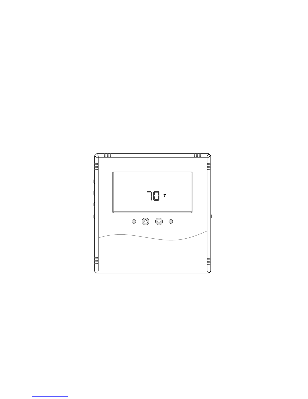
Figure 1 — T9000 Front View
Fan
Heat
Cool
Up
Down
F/C
Program
Run
Clock
Light
Th
Fan Auto
COOL
OFF
70
O
O
11: 20
A
M
Day
Set Point
T9000 — MODEL 124 Operation Guide
©2008 ENERNET Corporation • www.enernetcorp.com • 315-449-0839 Pub No. 12401-051707 / Page 2 of 17
+
-
INTRODUCTION
The T9000 Wireless Temperature Control is a two-part wireless
thermostat system designed to provide precision temperature
control without the installation labor and expense of wiring.
Powered by AA batteries, the thermost at can ope rate continuous ly
for approximately 18 months, and ca n be mounted in any suitabl e
location that will provide good temperature control. A large LCD
display (Figure 1) provides the user with current room
temperature, set point temperature, time, program interval, and
other system status information. In hotel applications,
programming, clock set up buttons and associated display
information are typically not displayed. The second part of the
T9000 system is called a Remote Control Node or “RCN ”. An RCN
interfaces with the HVAC equipment, and communicates with its
thermostat using unlicensed 900 MHz, radio frequency energy. At
the time of installation, the T9000 thermo stat is linked to one or
more RCN controls. The thermostat and RCN that have been
linked will not interfere with, or be affected by any other thermostat
or RCN in adjacent rooms, apartments, or neighboring homes.
BATTERIES
Installing / Changing
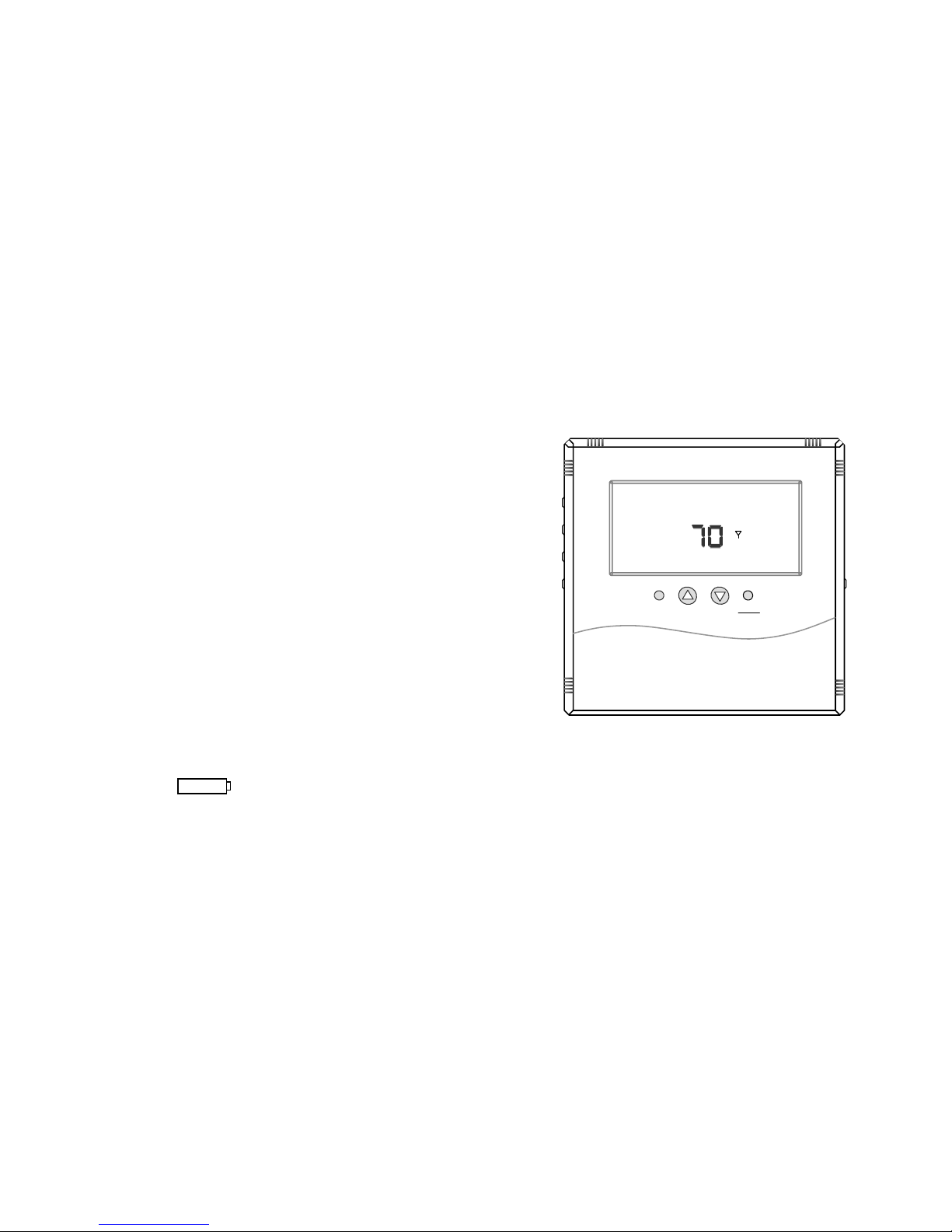
A low battery icon will light on the thermostat display
when the batteries are within approximately one week of being
exhausted. The T9000 is designed to use standard AA size 1.5
volt alkaline batteries. If the batteries become completely
depleted, the heating/cooling system will go to the” OFF” state.
Figure 1 — T9000 Front View
Replacing Batteries
To open the thermostat, use both h ands, press the two push-tabs
on the bottom of the thermostat housing with your thumbs while
pulling the front of the thermostat away from the base - Figure 2.
Fan
Heat
Cool
U
p
Down
Fan
COOL
OFF
70
O
11:20
Day
Set Point
F/C
Program
Run
Clock
Fan Auto
Light

T9000 — MODEL 124 Operation Guide
©2008 ENERNET Corporation • www.enernetcorp.com • 315-449-0839 Pub No. 12401-051707 / Page 3 of 17
Figure 2 — Opening Thermostat
The T9000 operates with either 2 or 4 AA batteries. Four (4)
batteries double the time between ba ttery changes (the average
user can expect 1 to 1.5 years of battery life). Batteries are
paired, one set on top of the other (see Figure 3).
Figure 3 — Battery Location
Note: Do not mix old and new batteries. When batteries are
changed, replace them all at the same time.
Programmed data for heating, co oling and time of day w ill be lost
when all, batteries are removed or de pleted an d wil l have to b e reentered along with resetting the clock. To avoid this, batteries can
be replaced one set at a time b efore they are depleted. However,
after the first set is replaced, immediately replac e the second set
with new batteries.
MOUNTING
Find a suitable location for mounting your thermostat, preferably
an interior wall, centrally located within the conditioned space at
about 5' above the floor. Try not to locate the thermostat in a
place where it could be exposed to heat s uch as warm air v ents or
in a place where it could be exposed to direct sunlight.
Wall-Mount
The T9000 back mounting plate provides six (6) mounting holes.
The upper and lower holes on the vertical centerline will match up
with screw positions of a standard elec trical switch box or drywall
mounting ring.
Step 1
Remove the back plate from the thermostat housing, (Figure 2)
and use it to mark locations for mounting holes. While operation of
Battery orientation is
critical.
Thermostat
opened back
Thermostat will operate on
either Set A, Set B or
both. When changing,
replace with all new
batteries. Never use a
mix of old and new.
Circuit Board
Set A
Set A
Set B Set B
Base Plate
Front Cover
Latches
T9000 — MODEL 124 Operation Guide
©2008 ENERNET Corporation • www.enernetcorp.com • 315-449-0839 Pub No. 12401-051707 / Page 4 of 17
the thermostat is not affected by orienta tion, we reco mmend using
a level across the top or side of the base plate to ensure a
professional installed appearance.
Step 2
Drill 3/8” holes and insert drywall fasteners (#6 screws
recommended) and fasten the back plate to the wall.
Back Stand
Located on the back of the housing is a built-in hinged stand
support. This feature permits the thermostat to stand on a flat
surface such as a table or shelf, in the event that permanent
mounting to a wall is not desired.
BUTTONS
A four button cluster is located on the front of the T9000.
Figure 4 — Front Button Cluster
These buttons are used in adjusting fan operation, changing the
set point temperature up or down and changing the operating
mode of the thermostat. (Figure 13 provides definition of all button
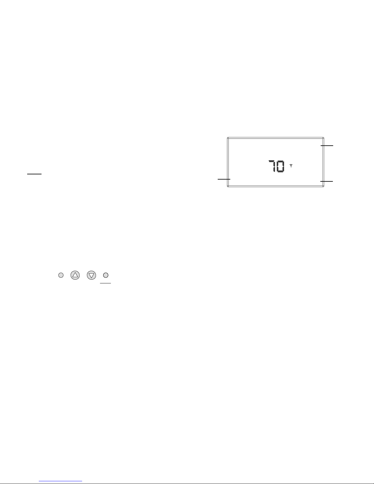
and display items.) Figure 5 shows the display items that are
changed by these four buttons in normal operatio n .
Figure 5 — General Operation Display
Note that the UP, DOWN and HEAT/COOL buttons are als o used
in setting the clock, programming the thermostat and linking to
nodes — covered later in this manual.
Four buttons located on the left side of the thermostat (Figure 1)
control display of temperature in either Fahrenheit or Celsius,
programming, clock setup and cont rol of wheth er the thermost at is
under manual or program control.
F / C - Toggles Fahrenheit Celsius display
Program set up button
Run – Sets program or manual mode of operation
Clock set up button
BACKLIGHT
A single button on the right side of the thermostat activates the
display backlight. When pressed, the backlight will illuminate the
display briefly and turn off. If other buttons are pressed
immediately after the backlight button, the display will stay
Fan
Heat
Cool
Up
Down
Fan Auto
COOL
70
O
O
Set Point
Mode of
operation
Set Point
Fan
status
 Loading...