

Pub No. 13001-082207
Model 130 User Guide
Communicating Thermostat Wireless RS485 Accessory
ENERNET Corporation Copyright 2007

MODEL 13000 Application Guide
ENERNET CORPORATION IS NOT RESPONSIBLE FOR ANY
RADIO OR TV INTERFERENCE CAUSED BY UNAUTHORIZED
MODIFICATIONS TO THIS EQUIPMENT. SUCH
MODIFICATIONS COULD VOID THE USER’S AUTHORITY TO
OPERATE THE EQUIPMENT.
THIS EQUIPMENT COMPLIES WITH PART 15 OF THE FCC
RULES. OPERATION IS SUBJECT TO THE FOLLOWING TWO
CONDITIONS: (1) THIS DEVICE MAY NOT CAUSE HARMFUL
INTERFERENCE, AND (2) THIS DEVICE MUST ACCEPT ANY
INTERFERENCE RECEIVED, INCLUDING INTERFERENCE
THAT MAY CAUSE UNDESIRED OPERATION.
ENERNET CORPORATION PROVIDES THIS PUBLICATION “AS
IS” WITHOUT WARRANTY OF ANY KIND, EITHER EXPRESS
OR IMPLIED, INCLUDING, BUT NOT LIMITED TO, THE IMPLIED
WARRANTIES OF MERCHANTABILITY OR FITNESS FOR A
PARTICULAR PURPOSE.
THIS MANUAL MAY CONTAIN TECHNICAL INACCURACIES
AND/OR TYPOGRAPHICAL ERRORS. CHANGES ARE
PERIODICALLY MADE TO THIS MANUAL, WHICH ARE
INCORPORATED IN LATER EDITIONS.
ENERNET CORPORATION MAY MAKE CHANGES AND
IMPROVEMENTS TO THE PRODUCT(S) AND/OR PROGRAMS
DESCRIBED IN THIS PUBLICATION AT ANY TIME WITHOUT
NOTICE.
IN NO EVENT WILL ENERNET CORPORATION BE LIABLE FOR
DAMAGES, INCLUDING LOST PROFITS, LOST SAVINGS OR
OTHER INCIDENTAL OR CONSEQUENTIAL DAMAGES
ARISING OUT OF THE USE OF OR INABILITY TO USE SUCH
PRODUCT, EVEN IF ENERNET CORPORATION OR AN
APPROVED RESELLER HAS BEEN ADVISED OF THE
POSSIBILITY OF SUCH DAMAGES, OR FOR ANY CLAIM BY
ANY OTHER PARTY.
E NERNET
Corporation
307 Dewittshire Road, Syracuse, New York 13214
Phone: (315) 449-0839 Fax: (315) 449-3056

MODEL 13000 Application Guide
ANTENNA
The wireless RF equipment described in this document may be
supplied with one of two possible antenna configurations.
Stick-On 1/2-wave Dipole Antenna:
Antenna Factor P/N ANT-916-MHW -RPS
PCB Mounted 12-Inch Coaxial Monopole:
ENERNET P/N 060-012
EQUIPMENT MANUFACTURER (OEM)
The Original Equipment Manufacturer (OEM) must ensure that
FCC labeling requirements are met. This includes a clearly visible
label on the outside of the final product enclosure that displays the
following:
CONTAINS FCC ID: TGD13000

MODEL 13000 Application Guide
PB1— SERIAL LOOP BACK TEST
second period during
PB1 PB3 PB2
J2
Power Supply
Network
Thermostat
Crystal
Serial Interface
8870 Thermostat
RF XCVR
RF Section
ANT
Communication Terminals
YEL (A+)
BLUE (A-)
WH (B+)
GRN (B-)
D5D4
24VAC Power
A valid 8870 thermostat command is sent ov er the
RS485 interface. A valid return data string is
Processor
D3
D1D2
RED ( R )
BLK ( C )
expected.
? Green LED (D5) flash = PASS
? Red LED (D4) flash = FAILED.
PB2 — RF COMMUNICATION TEST
Initiates a 5-second communication test with the
model 130 Master transceiver it has been linked to. .
? Green LED (D5) flash = PASS
? Red LED (D4) flash = FAILED
PB3 — CONFIGURATION SETUP
Holding PB3 down for 3-seconds places unit into
configuration setup (see Configuration Setup section
for details).
PB2 + PB3 — INSTALLATION MODE
Simultaneously pressing PB2 & PB3 places the
model 130 Remote Communication Node (RCN) into
Installation Ready mode for a 5which time it can be linked to a Master Transceiver.
The Yellow LED (D3) and Green LED (D2) will
simultaneously light to indicate the RCN is in
Installation Ready mode.
Figure 1: Aprilaire 8870 Thermostat — Model 130 Remote Communication Node
1

MODEL 13000 Application Guide
PB1— SERIAL LOOP BACK TEST
PB1 PB3 PB2
J2
Power Supply
Network
NI-700
Crystal
Serial Interface
NI-
700
ANTENNA
RF XCVR
RF Section
P/N: ANT-916-MHW-RPS
ANT
A valid 8870 thermostat command is sent over the
RS485 interface. A valid return data string is
expected. Green LED (D5) flash indicates a pass.
Processor
Red LED (D4) indicates a failure.
Note that the Master Transceiver position is not
interfaced with an 8870 thermostat and will therefore
D5D4
D3
D1D2
9-Pin Serial Port
12VDC PWR
RED ( + )
BLK ( - )
indicate a loop back test failure.
PB2 — LINK
Pressing PB2 when an RCN is in the Installation
Ready mode will link that RCN to the Master
Transceiver.
PB3 — CONFIGURATION SETUP
Holding PB3 down for 3-seconds places unit into
configuration setup (see Configuration Setup section
for instructions).
Figure 2: NI-700 — Model 130SMA Master Transceiver
2

MODEL 13000 Application Guide
INTRODUCTION
The model 130 series RF transceivers are designed to provide a
wireless, mesh network RS485/422 interface over an unlicensed
900MHz RF data channel. The application discussed in this
manual utilizes an NI-700 NetLinx Integrated Controller made by
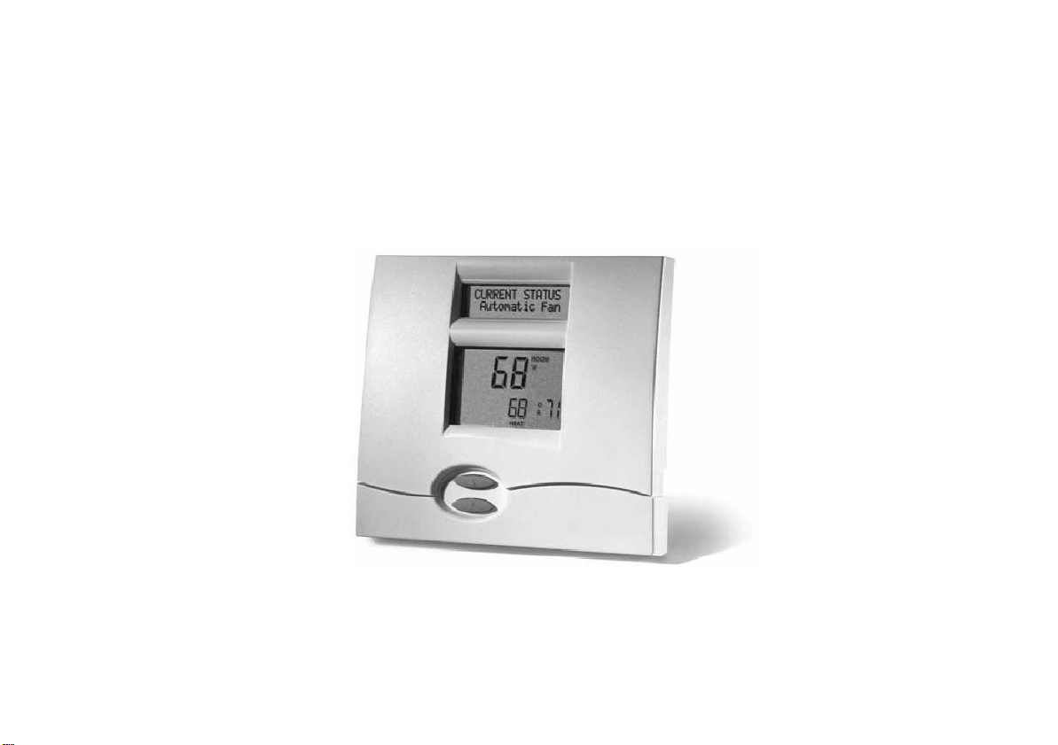
AMX and the Aprilaire model 8870 Communicating Thermostat.
The Aprilaire 8870 thermostat supports a hardwired RS485/422
serial communication channel such as that provided by an NI-700
serial port. Through the NI-700, information can be received from
and commands can be sent to individually addressed thermostats.
As many as 64 thermostats can be connected on a single network.
The model 130 series RF transceiver provides a transparent
wireless communication channel between an NI-700 and its
associated thermostats.
There are two physical configurations of the model 130 as well as
two operating configurations. Figure 1 above shows a model 130
Remote Communication Node or RCN, which is located with an 8870
thermostat. This configuration provides two power wires, four
RS485/422 serial communication wires and a 12” long coaxial
antenna. It should be powered by the same 24VAC as the
thermostat. (Black ‘C’ wire MUST connect to the thermostat ‘C’
wire - Red ‘R’ wire MUST connect to thermostat ‘R’ wire.) Figure 2
depicts a model 130SMA Master Transceiver. In this physical
configuration, the four serial communication wires are replaced by
a 9-pin female serial connector. The antenna is replaced by the
SMA style threaded connector which mates to a remote antenna
connector. Operating configuration setup is covered later in this
manual.
3

MODEL 13000 Application Guide
OPERATING CONFIGURATION
Model 130 series RF transceivers can be configured to operate as
either a Master Transceiver or as a Remote Communication Node
(RCN) And, the mesh network / repeater function can be turned on
or off (factory default is off). Because of the physical configuration
differences in the two models it is unlikely to be necessary to alter
the Master Transceiver / RCN configuration.
Two configuration property tables are accessible by the user. The
first property table sets Mode of Operation, The second sets the
mesh network / repeater function on or off. The configuration
tables that follow provide operational descriptions and factory
default settings. Selections are indicated through the FLASH COUNT of LED’s D1 and D2. (Refer to Figure 1 and 2 above.)
D2 repeatedly flashes 1 or 2 times to indicate the property table
that is active. D1 flashes 1 or 2 times to indicate the specific
operational ‘property’ selected.
(Refer to Figure 1 or 2 for button and LED locations)
PB3 (Configuration Setup) will switch the unit into and out of the
configuration mode. Holding PB3 down for approximately 3seconds will take you into the configuration area. To leave the
configuration area, simply press and release PB3. PB2 selects
configuration table 1 or 2, which is indicated by D2 FLASHCOUNT .
PB1 selects the configuration property as indicated by D1 FLASHCOUNT. Pressing PB 3 to leave the configuration area will save
changes made. To review or change the configuration, refer to the
configuration tables below for descriptions and perform the
following:
1. Press and hold PB3 until LED indicator lamps D2 & D1 flash
alternately. (NOTE: At any time during the setup process PB3 can
be pressed again to return to normal operation.)
2. D2 will flash once indicating Table 1, Operating Mode
configuration, followed by D 1 flashing 1 or 2 times indicating the
specific configuration in Table 1 that is currently active. (NOTE:
D2 and D1 will flash repeatedly to indicate the Table and the
configuration.) Pressing PB1 will advance the configuration option
by one. Press PB1 until the FLASH-COUNT corresponds to the
desired configuration. (Refer to Table 1.)
3. Press PB2 to advance to Table 2, Message Repeat
configuration. D2 will flash 2 times, followed by D1 flashing 1 or 2
times depending on how it is currently set. Press PB1 until the
FLASH-COUNT corresponds to the desired configuration.
4. Press PB3 to return to normal node operation, saving any
configuration changes you’ve just made.
4

MODEL 13000 Application Guide
M A S T E R T R A N S C E I V E R / R C N C O N F I G U R A T I O N — T A B L E 1
Remote Communication Node RCN*
1
(Factory Default)
CONFIGURATION
D2 D1
FLASH
COUNT
1 1
FLASH
COUNT
DESCRIPTION
Wires directly to an Aprilaire 8870 Communicating
Thermostat.
2 Master Transceiver 1 2 Plugs on to one of the RS485/422 serial ports of an NI-700.
* Factory default setting.
R E P E A T E R ON / OFF C O N F I G U R A T I O N — T A B L E 2
Mesh Repeater function OFF*
1
(Factory Default)
CONFIGURATION
2 Mesh Repeater function ON 2 2
* Factory default setting.
D2 D1
FLASH
COUNT
2 1
FLASH
COUNT
Does not repeat messages it hears from a Master
Transceiver or other RCN units. (Applies only to an RCN.)
Repeats messages it hears from a Master Transceiver or
other RCN unit. (Applies only to an RCN.)
DESCRIPTION
5

MODEL 13000 Application Guide
D2 D3
D2 D3
INSTALLATION / LINKING
A Master Transceiver and Remote Communication Node will not
operate as a system until they are linked together through the
installation linking process. The linking process binds one or more
RCN units to a Master so that they will communicate with each
other as a control system. There is no practical limit to how many
RCN units can be linked to a Master. Once linked, Remote
Control Nodes will only respond to the Master they are linked to.
Message traffic from other Master Transceivers and nodes will be
ignored. Master Transceivers and associated RCN units will not
interfere with or be affected by any other Master or RCN in
adjacent apartments, hotel rooms or neighboring homes. Linking
information is stored in non-volatile memory — It is not necessary
to re-link a Master and RCN if power is lost. Upon restoration of
power the units will continue to communicate as before.
NOTE:
If multiple installation teams are performing the linking process at the same
time, coordinate the activity to avoid the possibility of installers
simultaneously attempting to link RCN units.
For immediate visual confirmation of a successful link, it is recommended
that RCN’s and Master Transceivers are linked in close proximity to each
other.
LINKING PROCESS
Start the linking process by simultaneously pressing PB2 and PB3
on the Remote Control Node you wish to associate with a given
Master Transceiver. LED’s D2 and D3 will light and stay on for
approximately 5-seconds after you have simultaneously pressed
both buttons indicating an installation link period window is open.
D1
PB3
PB2
PB1
Simultaneously press PB2 and PB3 on any RCN circuit board to
initiate an installation period.
D1
PB3
PB2
PB1
At any time during the link period window, press PB2 on the
Master Transceiver. A successful link is indicated by green LED
D4 flash on the RCN. An unsuccessful link or installation period
timeout is indicated by red LED D5 flash.
6

MODEL 13000 Application Guide
Master
8870
NI-700
RF COMMUNICATION TEST
After RCN units have been linked to a Master and installed on
thermostat bases, a communication test should be run to ensure a
reliable communication path exists between each RCN and its
Master Transceiver.
Initiate a 5-second communication test with the Master transceiver
by pressing PB2 on the RCN under test. After the 5-second test
period a PASS/FAIL indication is given:
? Green LED (D5) flash = PASS
? Red LED (D4) flash = FAILED
Each model 130 wireless RS485/422 RCN can be operated with
or without mesh (message repeating) functions turned on. Factor y
default is repeater OFF. With the repeater function off, the Master
Transceiver must be able to directly communicate with each of its
RCN’s. While the repeater function allows the system to over
come RF range limitations, unnecessary repeats adds traffic to the
network. A better use of the function is to selectively enable it.
Figure 3 is an example of using the repeater function selectively.
In this example case, a Master Transceiver directly communicates
with RCN 1, 2 and 3. RCN 4 and 5 however are out of range.
RCN 3 is the closet RCN to 4 and 5. Its repeater function is
enabled, forming the bridge between the Master and RCN units 4
and 5.
Figure 3: Mesh Repeater Example
RCN #1
Transceiver
8870
8870
RCN #4
8870
RCN #2
RCN #3
(Repeater on)
8870
RCN #5
7

Important Note:
The device cannot be sold retail,to the general public or by mail order.
The device should be installed by licensed professionals ( EUT sold to dealer who hire
installers)
This device complies with Part 15 of the FCC Rules. Operation is subject to the following two conditions:
(1) this device may not cause harmful interference, and (2) this device must accept any interference
received, including interference that may cause undesired operation.
 Loading...