

ENERNET 12400 User Manual
Thermostats
Wireless Digital Programmable
ge.com
Backlight . . . . . . . . . . . . . . . . . . . . . . . . . . . . . . . . . . . . . . .5
Batteries . . . . . . . . . . . . . . . . . . . . . . . . . . . . . . . . . . . . . . . .4
Buttons . . . . . . . . . . . . . . . . . . . . . . . . . . . . . . . . . . . . . . . . .5
Clock . . . . . . . . . . . . . . . . . . . . . . . . . . . . . . . . . . . . . . . . . . .6
Exiting Program Mode . . . . . . . . . . . . . . . . . . . . . . . . . .9
Frequently Asked Questions . . . . . . . . . . . . . . . .13–14
Important Safety Information . . . . . . . . . . . . . . . . . . .2
Installing or Removing Receiver . . . . . . . . . . . .10–12
Introduction Overview . . . . . . . . . . . . . . . . . . . . . . . . . .3
Navigating . . . . . . . . . . . . . . . . . . . . . . . . . . . . . . . . . . . . . .9
Programming . . . . . . . . . . . . . . . . . . . . . . . . . . . . . . . .7–8
Run Button . . . . . . . . . . . . . . . . . . . . . . . . . . . . . . . . . . . . .9
Specifications . . . . . . . . . . . . . . . . . . . . . . . . . . . . . . . . . . .2
Troubleshooting Tips . . . . . . . . . . . . . . . . . . . . . . . . . . .15
Warranty . . . . . . . . . . . . . . . . . . . . . . . . . . . . . . . . . . . . .16
RAK348R1 – Receiver
RAK348T1 – Thermostat
RAK364R1 – Receiver
RAK364T1 – Thermostat
Owner’s Manual
49-7574 06-07 JR
Español
Para consultar una version
en español de este manual
de instrucciones, visite nuestro
sitio de internet ge.com.
Française
Pour une version française de
ce manuel d’utilisation, veuillez
visiter notre site web à l’adresse
www.electromenagersge.ca
with Receivers
49-7574 v07 6/15/07 9:39 AM Page 1
Important safety information.
Specifications.
WARNING! Always turn off power at the main power supply before
installing or removing the thermostat receiver.
GE IS NOT RESPONSIBLE FOR ANY RADIO OR TV INTERFERENCE CAUSED BY UNAUTHORIZED
MODIFICATIONS TO THIS EQUIPMENT. SUCH MODIFICATIONS COULD VOID THE USER’S
AUTHORITY TO OPERATE THE EQUIPMENT.
THIS EQUIPMENT COMPLIES WITH PART 15 OF THE FCC RULES. OPERATION IS SUBJECT
TO THE FOLLOWING TWO CONDITIONS: (1) THIS DEVICE MAY NOT CAUSE HARMFUL
INTERFERENCE, AND (2) THIS DEVICE MUST ACCEPT ANY INTERFERENCE RECEIVED,
INCLUDING INTERFERENCE THAT MAY CAUSE UNDESIRED OPERATION.
• Do not use air conditioning when the outdoor temperature is below 50 degrees; this can
damage your A/C system and cause personal injuries.
• Use this thermostat only as described in this manual.
Electrical ratings: • Thermostat: DC Power 3.0 VDC (4 “AA” batteries included); 40 mA
• Receiver: 24 VAC (18–30 VAC); 25 mA
Operating temperature range: 40°F–99°F (4°C–37°C)
Temperature set range
Heat mode: 50°F (10°C)–85°F (29°C)
Cool mode: 64°F (18°C)–99°F (37°C)
Accuracy: ± 1°F (± 0.5°C)
System configurations: 2-stage heat (heat pump/resistance heat); 1-stage heat (resistance
heat); 1-stage cool
Timing: Anti-short cycle: 3 minutes (minimum compressor
run time/off time)
Terminals: R, GL, GH, B, Y, W, C
2
49-7574 v06 6/7/07 9:44 AM Page 2
3
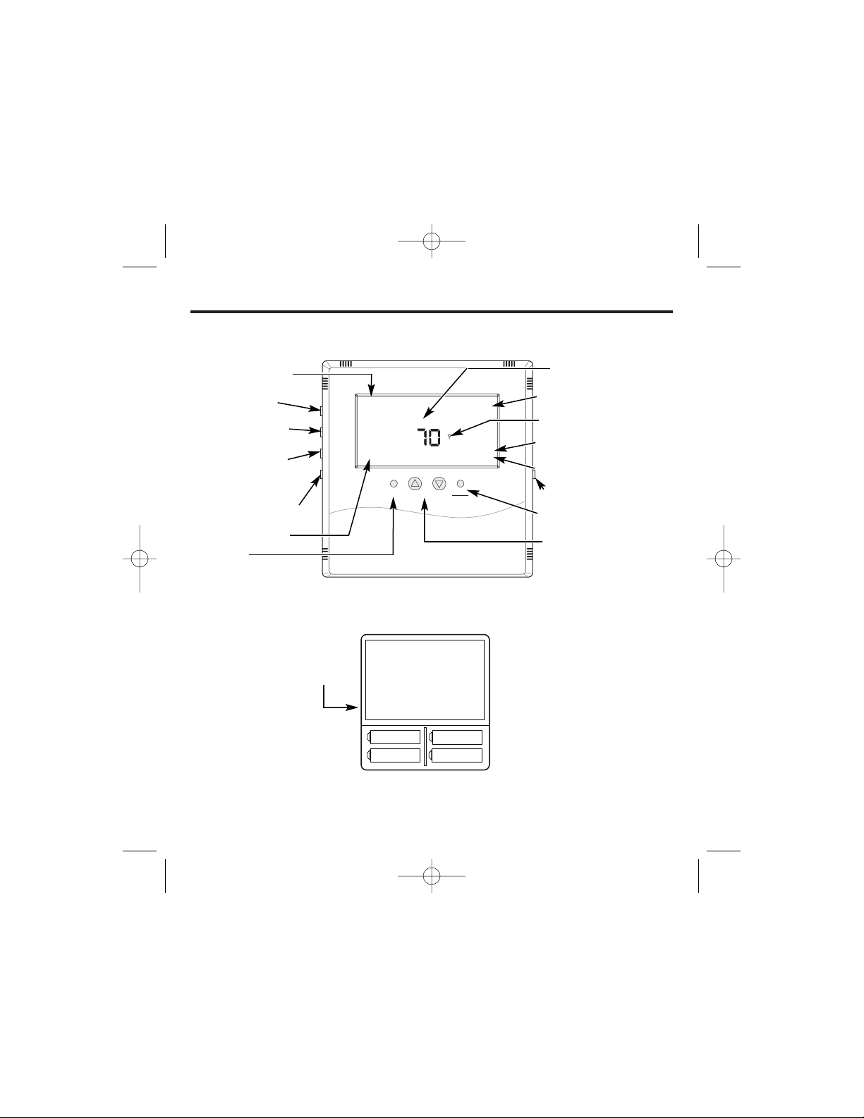
INTRODUCTION OVERVIEW
THERMOSTAT CONTROL – Back
A
Time and day
of week
Includes program period –
Morning, Day, Evening, Night
Starts and stops the
program – Holds Set Point
when program is not
running
Toggles display –
Fahrenheit/Celsius
Puts thermostat into the
clock setup mode
Thermostat will operate
on either Set A, Set B or
both. When changing,
replace with all new
batteries. Never use a
mix of old and new.
Battery orientation is
critical.
Heating and cooling programs are held in memory. If the batteries are removed or depleted, the thermostat
and receiver(s) will remain linked but the programming information and the clock will need to be reset .
Thermostat
opened
back
Puts thermostat into
the program setup mode
Fan operating status
Fan control
Operating mode indication –
HEAT, COOL, OFF
RF connection with a control
mode
Indicates holding of Set Point
temperature – See Run button
Current Set Point temperature
Momentary backlight button
Changes operating mode –
HEAT, COOL, OFF
Changes Set Point temp –
Also used in clock and
program setup
Circuit Board
Set A
Set A
Set B
Set B
THERMOSTAT CONTROL – Front
49-7574 v06 6/7/07 9:44 AM Page 3
F/C
PGM
Run
Clock
11:20
Fan Auto
M
Th
Day
Fan
Up
Down
COOL
OFF
O
Set Point
O
70
Light
Heat
Cool
Installing/Changing
A low battery icon will light on the thermostat display when the batteries are within a
week or two of being exhausted. The thermostat is designed to use standard AA-size 1.5 volt
batteries. If the batteries are depleted, the heating/cooling system will go to the OFF state.
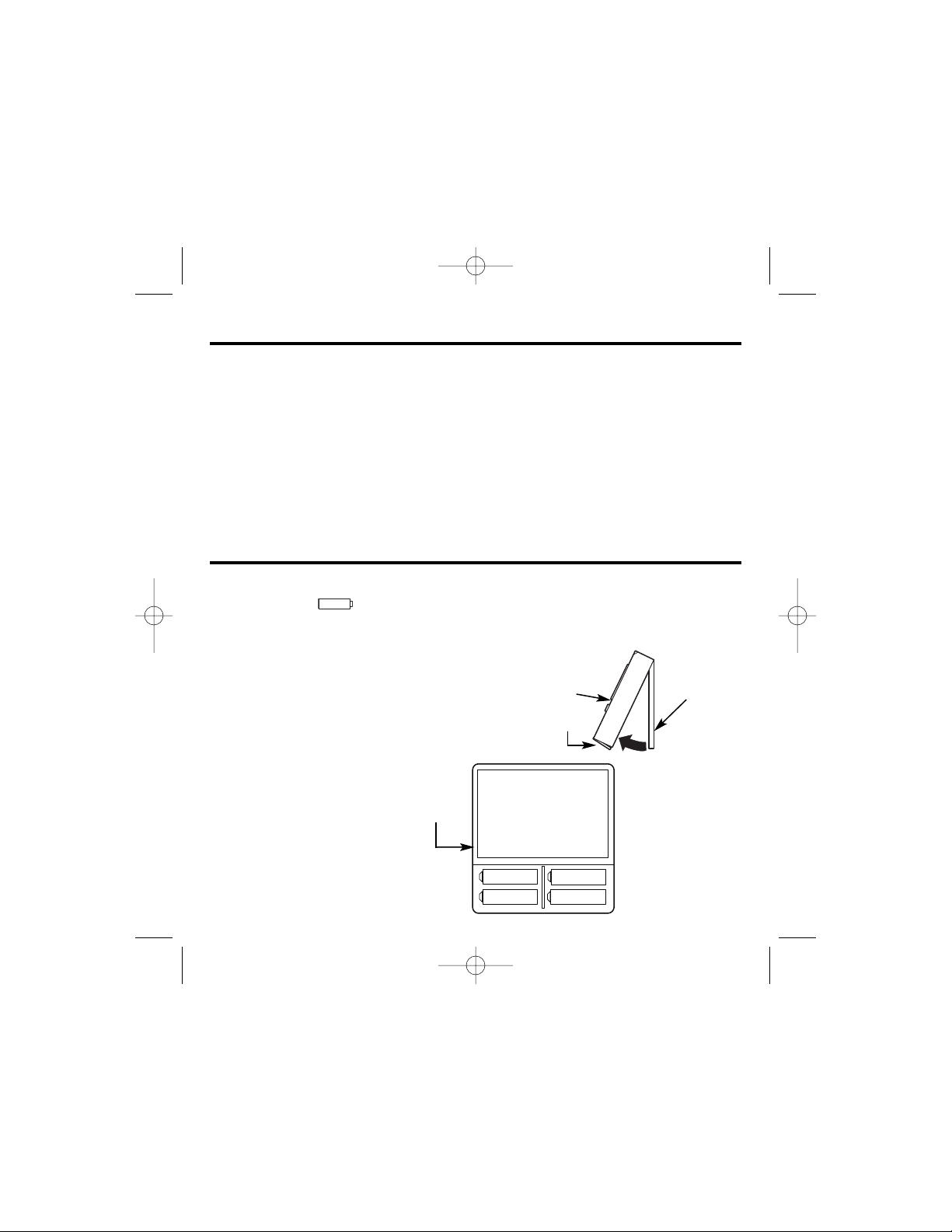
Replacing Batteries
To open the thermostat, remove the security screw
(#2 Phillips or #2 security screw). Using both hands, press
the two push-tabs on the bottom of the thermostat housing
with your thumbs, while pulling the front of the thermostat
away from the base.
The thermostat operates with 4 AA batteries.
Batteries are paired, one set on top
of the other.
4
Introduction.
This two-part wireless thermostat system is designed to provide precision temperature control
without the installation headaches and expense of wiring. Powered by four AA batteries, the
thermostat will operate for approximately 1 year, and can be mounted in any suitable location
that will ensure good temperature control. A large LCD display provides the user with current
space temperature, set point temperature, time, program interval and other system status
information. The second part of the system is the receiver. The receiver interfaces with the
desired HVAC equipment and communicates with its thermostat using unlicensed 900MHz
radio frequency energy. At the time of installation, the thermostat is linked to one or more
receivers. A thermostat and receiver that have been linked will not interfere with or be affected
by any other thermostat or receiver in adjacent rooms, apartments or neighboring homes.
Batteries.
Thermostat
cover
Latches
Base plate
Thermostat will operate
on either Set A, Set B or
both. When changing,
replace with all new
batteries. Never use a
mix of old and new.
Battery orientation is
critical.
Circuit Board
Set A
Set A
Set B
Set B
Thermostat
opened
back
49-7574 v06 6/7/07 9:44 AM Page 4
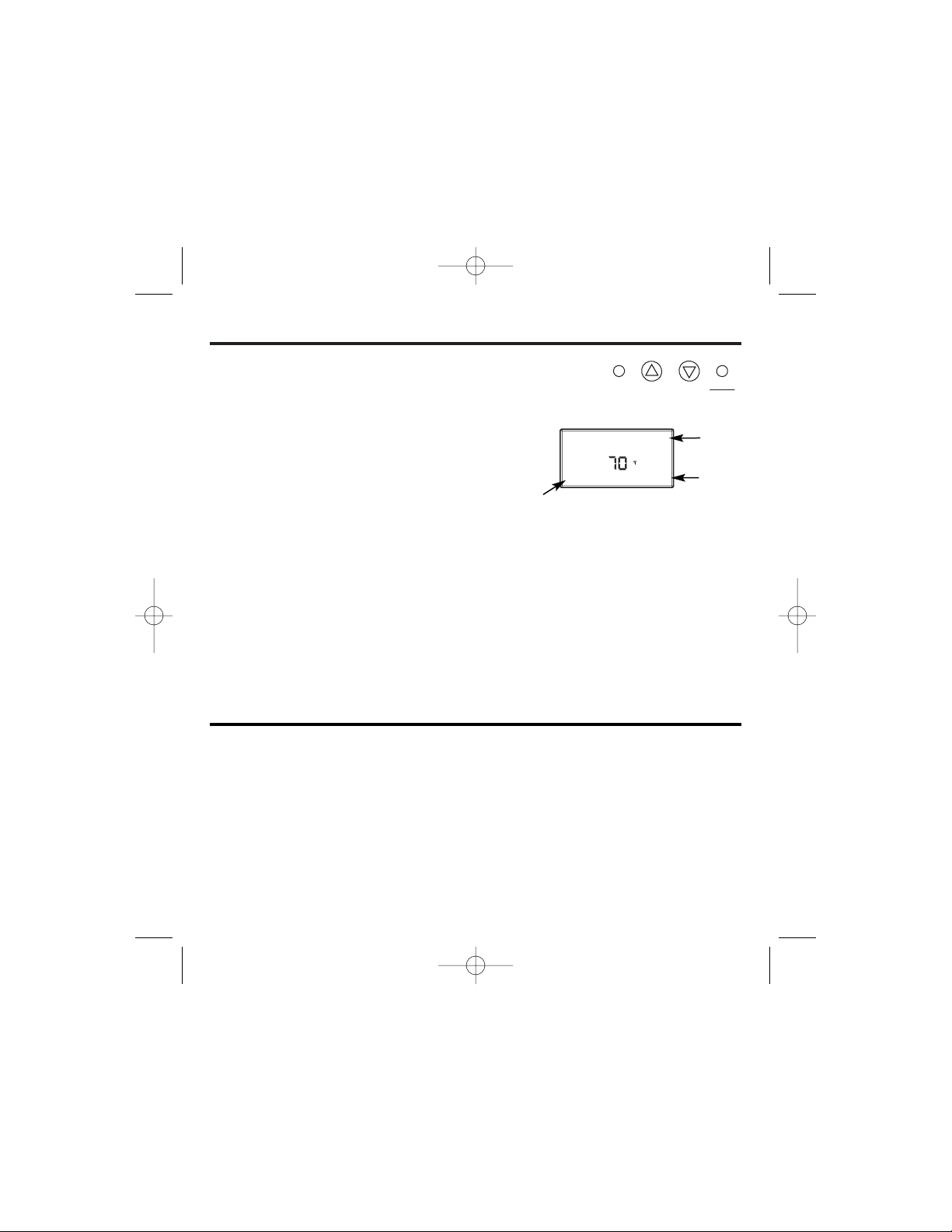
Buttons.
A four-button cluster is located on the front of the thermostat.
These buttons are used in adjusting fan operation, changing
the set point temperature up or down and changing the
operating mode of the thermostat. To the right are the
display items that are changed by the four buttons in
normal operation.
Note that the UP, DOWN and HEAT/COOL
buttons are also used in setting the clock and programming the thermostat and linking to
receiver(s). This will be covered in the following sections of the manual.
The four buttons located on the left side of the thermostat control the display of the
temperature in either Fahrenheit or Celsius, programming and clock set up. These buttons
also allow manual or program control.
• F/C – Toggles between the Fahrenheit and Celsius displays
• Program set-up button
• Run – Sets the program or manual mode of operation
• Clock set-up button
Mode of
operation
Set Point
Backlight.
A single button on the right side of the thermostat activates the display backlight. The backlight
will illuminate the display after the last button is pressed. Backlighting takes significant energy
from the batteries and should be used sparingly. Frequent use of the backlight function will
noticeably reduce battery life.
5
Fan status
49-7574 v06 6/7/07 9:44 AM Page 5
Fan Auto
Fan
Down
Heat
Cool
Up
COOL
O
Set Point
O
70
 Loading...