

Enerlites PL20R, PLBPC Installation Instructions Manual
INSTALLATION INSTRUCTIONS
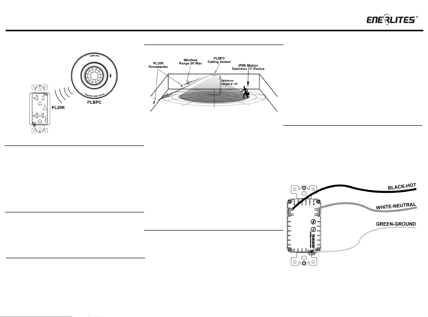
PL20R and PLBPC
COVERAGE
Wireless Plug Load Control
The PLBPC provides a 360° coverage pattern. The coverage shown represents walking
motion at a mounting height of 8ft. For building spaces with lower levels of activity or with
obstacles and barriers, coverage size my decrease.
SPECIFICATIONS
Voltage (PL20R)..............................................................................................120VAC, 60HZ, 20A
Motor Load............................................................................................................................1/2 HP
Time Delay......................................................................................................................30 minutes
Operating Temperature ................................................................................................30°to 120°F
Relative Humidity................................................................................20% to 90% non condensing
Operating Frequency...........................................................................................................315MHz
Reception Sensitivity..........................................................................................................-105dBm
Sensor Standby Current………....…..…………......................................................................200uA
Wireless Transmitting Current...................................................................................................5mA
Max Wireless Range..................................................................................................................24ft
Ceiling Sensor Battery Requirement........................................................................2 AA (Included)
Location: The PLBPC ceiling sensor should be mounted in a location free of obstruction
from furniture, plants, walls and vibration. The sensor must be mounted a minimum of 4ft
away from any air vents (registers). Avoid mounting the sensor close to heat source.
When mounting directly to a ceiling fixture,the lens of the sensor must be below the
lowest point of the fixture
The ceiling sensor is designed for a ceiling height or about 8-10 feet. Because of the
umbrela shaped coverage pattern, mounting above or below the recommended height
could reduce the coverage range and sensitivity.
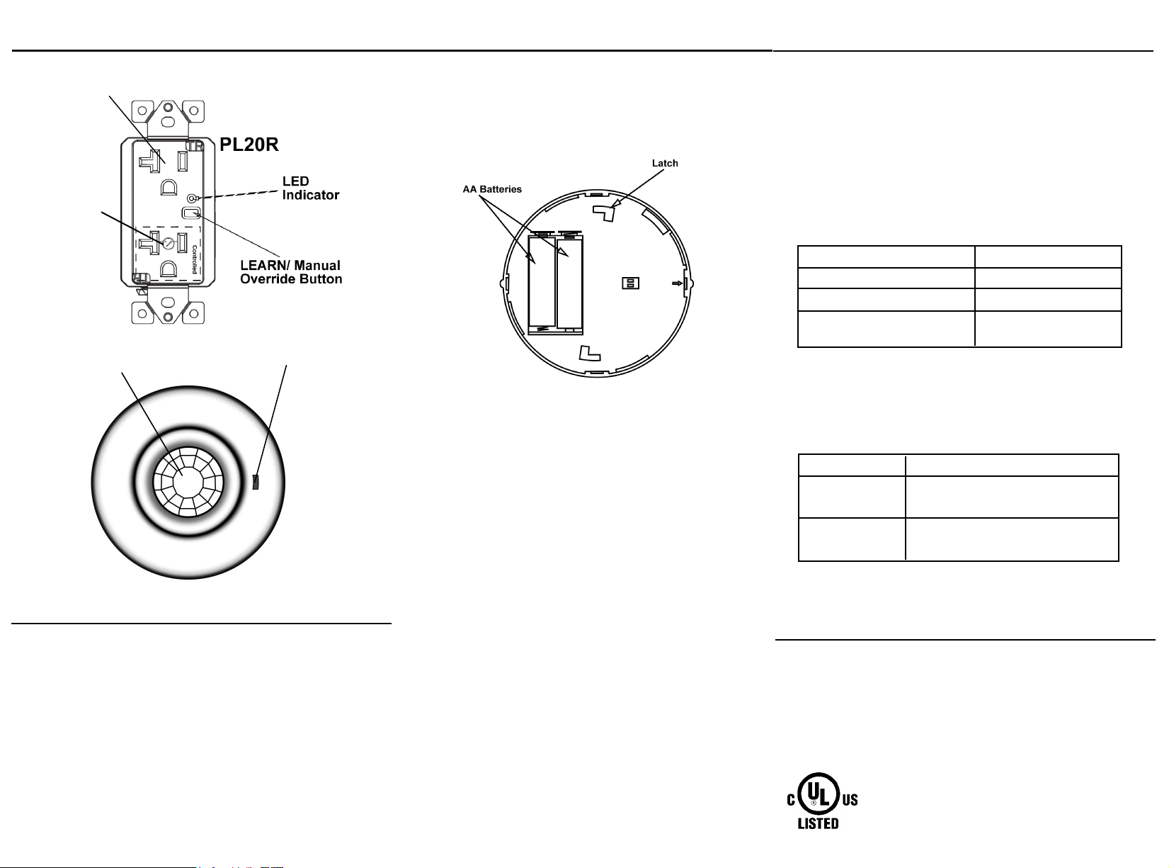
DESCRIPTION/ FEATURES
The PL20R and PLBPC are Wireless Plug Load Controls that are code compliant with 2013
California Title 24. The powerful 20A Tamper Resistant Smart Duplex Receptacle has
Controlled and Uncontrolled receptacles, an LED indicator, and a Manual override button. The
Controlled Plug Load will turn ON when motion is detected by the ceiling sensor and will turn
off 30 minutes after the room is vacated. The PIR ceiling sensor is battery operated so there is
no need for expensive in-wall wiring between the sensor and receptacles. Each PIR sensor
can pair up more than the 6 recommended receptacles with a wireless range up to 24' so it
can operate in large rooms such as conference rooms and lobbies.
Ideal Solutions for Wireless Plug Load Control
• Hotel guest room: flat screen TV's, floor lamps, task lamps, and coffee maker.
• Private offices: monitors, desk lamps, desk fan, personal heater, flat screen TV, and printer.
• Breakrooms: toasters, coffee maker, microwaves, flat screen TV's, and vending machines.
• Waiting rooms: flat screen TV's, and table lamps.
• Copier rooms: monitors, shredders, copier machines, hole punch machines, flat screen TV's.
1
WARNING
Turn the POWER OFF at the circuit breaker before
installing the receptacle.
Read and understand these instructions before installing. This device is intended for
installation in accordance with the National Electric Code and local regulations. It is
recommended that a qualified electrician performs this installation. Make sure to turn off
the circuit breaker or fuse(s) and make sure power is off before wiring the device.
Use copper wires only.
•
Make sure the sensor's view of the entrances is not blocked by the door
when it is opened.
•
Do not mount sensors close to air vents.
•
Cover the main walkways
•
Try to avoid having the sensor looking out the door of the space
2
IMPORTANT NOTES BEFORE YOU PROCEED :
• Check with your electrician for maximum receptacles allowed per branch circuit.
• A PLBPC sensor can control PL20R receptacles that are installed on different
branch circuits.
• Exercise extreme caution when using the PLBPC to control appliances. It can be
activated from a room different than the controlled appliance so an unintentional
activation may occur if motion is detected. Unattended or unintentional operation
of connected appliance could result in hazardous conditions.
• Automated devices should never be used to supply power to or control medical
monitor and/or life support equipment.
WIRING DIRECTIONS
Insert wires through the terminal holes in the back, then tighten
terminal screws.
• Connect Black HOT wire to the HOT terminal (brass screw).
•
Connect White NEUTRAL wire to the NEUTRAL terminal (silver screw).
Connect GREEN or BARE wire to the GROUND terminal (green screw).
•
3
PL20R DIAGRAM
Always ON
Receptacle
Controlled
Receptacle
MOUNTING PLBPC
1. Secure the mounting bracket to the ceiling using provided screws, anchors and
double-sided tape.
2. Align the latch on the sensor to the mounting bracket.
3. Latch the sensor by turning it counter-clockwise.
OPERATING THE SENSOR AND RECEPTACLE(S)
Operating
The "Always ON" receptacles will always have power as long as the circuit
breaker is ON. The "Controlled"receptacles will turn ON and stay ON as long
as motion is detected and turn off 30 minutes after the last motion detected.
The "Controlled" receptacle can also be operated manually by pushing the
manual override button located on the receptacle.
Low Battery Indicator
The LED indicator on the sensor will flash constantly when the battery on the
sensor is running low.
LED Indicator on Receptacle:
LED indicator Indication
Flashes rapidly for about 45 seconds
Solid ON for 2 seconds (following Learn mode)
Quick flashes twice, stops 1 second, and then
quick flashes twice (Repeat)
Receptacle is in Learn mode
Receptacle is paired
Device is in trouble mode
PIR Lens
LED Indicator
CODE LEARNING
BEFORE Installing the sensor onto the ceiling, you must pair all
receptacles with the PLBPC ceiling sensor. Six receptacles are
recommended per sensor.
1. Remove the battery from the PLBPC sensor.
2. Power on the receptacles once they're all connected and wall plates are installed.
3. Press and hold the "LEARN" button for 15 seconds on the receptacle.
4. Once the receptacle is in LEARN mode,
sensor. NOTE: The receptacles will be in LEARN mode for about 45 seconds.
5. Wait a few seconds for the receptacle to pair with the PLBPC.
6. Repeat steps 1-5 for each receptacle to be paired (Multiple receptacles can be
paired simultaneously)
7. Test all receptacles to ensure that they're operating correctly.
8. Install ceiling sensor onto ceiling.
install both batteries into the PLBPC
4
LED Indicator on Sensor will quickly blink 3 times when battery is installed
Button Functions on Receptacle:
Button Press
FCC COMPLIANCE STATEMENT
FCC Grant of Equipment Authorizations of this device and transmitters installed in this device
can be found at FCC website by entering the FCC ID number on the device.
Caution: Changes or modifications not expressly approved by the part responsible for
compliance could void the user’s right to operate the equipment.
This device complies with Part 15 of the FCC Rules. Operation is subject to the following two
conditions: (1) this device may not cause harmful interference, and (2) this device must accept
any interference received, including interference that may cause undesired operation of the
device.
This equipment has been tested and found to comply with the limits for a Class B digital device,
pursuant to part 15 of the FCC rules. These limits are designed to provide reasonable protection
against harmful interference in a residential installation. This equipment generates, uses and can
radiate radio frequency energy and, if not installed and used in accordance with the instructions,
may cause harmful interference to radio communications. However, there is no guarantee that
interference will not occur in a particular installation. If this equipment does cause harmful
interference to radio or television reception, which can be determined by turning the equipment
off and on, the user is encouraged to try to correct the interference by one or more of the
following measures:
• Reorient or relocate the receiving antenna.
• Increase the separation between the equipment and receiver.
• Connect the equipment into an outlet on a circuit different from that to which the receiver is
connected.
• Consult the dealer or an experienced radio/TV technician for help.
5
Long-press( 10 seconds)
WARRANTY INFORMATION
This device is warranted to be free of material and workmanship defects for 2 years from the
date of purchase. Original receipt or proof of purchase from an authorized retailer must be
presented upon warranty claim. ALL claims must be verified and approved by Enerlites, Inc.
Warranties from other Enerlites products may vary. This warranty is nontransferable and
does not cover normal wear and tear or any malfunction, failure, or defect resulting from
misuse, abuse, neglect, alteration, modification, or improper installation. To the fullest extent
permitted by the applicable state law, Enerlites shall not be liable to the purchaser or end
user customer of Enerlites products for direct, indirect, incidental, or consequential damages
even if Enerlites has been advised of the possibility of such damages. Enerlites’ total liability
under this or any other warranty, express or implied, is limited to repair, replacement or
refund. Repair, replacement or refund are the sole and exclusive remedies for breach of
warranty or any other legal theory.
Short-press
Function
Manually turns ON/OFF the controlled
receptacle.
Receptacle enters LEARN mode.
6
© 2016 Enerlites Inc.
WWW.ENERLITES.COM
CA, U.S.A.
0210160046-02
 Loading...