

Enerlites MWOS Installation Instructions Manual

1
2
INSTALLATION INSTRUCTIONS
SPECIFICATIONS
DESCRIPTION
3
WARNING
Turn the POWER OFF at the circuit breaker before installing the
sensor
Read and understand these instructions before installing. This device is
intended for installation in accordance with the National Electric Code and local
regulations. It is recommended that a qualified electrician performs this
installation. Make sure to turn off the circuit breaker or fuse(s) and make sure
power is off before wiring the device.
Use copper wires only.
WIRING DIRECTIONS
As illustrated in Figure 1, The MWOS has a 180° PIR detection range with a
maximum distance of 40’ detection in front of the sensor and 20' on the sides
for a total of 1200 s.f. The Ultrasonic detection range is 20' in the front and 10'
on the sides for a total of 400 s.f. For maximum results, the sensor must be
properly installed between the height of 4’ to 5’ and away from obstructions
such as walls, furniture and transparent barriers like Low-E glass.
The MWOS is a Multi-Technology Wall Sensor Switch that combines advanced
passive infrared (PIR) and ultrasonic technologies to help avoid false triggering.
Selectable operating modes allow the sensor to turn a load on, and hold it on as
long as either or both technologies detect motion. The sensor will automatically
shut off the load at the end of the selected time delay. The countdown of the
selected time delay starts after the last motion detected. The sensor is
customizable with dials that can adjust Time Delay, detection Range, ambient
Light Level, and switches to change between Occupancy/ Vacancy modes
and select PIR/ Ultrasonic
modes and levels.
1. Connect RED wire from sensor to the LOAD wire.
2. Connect BLACK wire from sensor to the HOT wire.
3. Connect WHITE wire from sensor to the NEUTRAL wire. The NEUTRAL
WIRE IS REQUIRED.
4. Connect GREEN wire from sensor to the GROUND wire.
ADJUSTMENT
MWOS
Multi-Technology PIR/Ultrasonic
Occupancy / Vacancy Sensor Switch
Incandescent ..........................................................................800VA@120VAC
Time Delay..........................................................................…… 15Sec to 30Mins
Light Level................................................................................... 100 Lux--Daylight
Fluorescent/Ballast.......................................800VA@120VAC /1600VA@277VAC
Operation Temperature....................................................................32° F--131° F
Voltage .............................................................................. 120/277VAC,50/60Hz
Motor ...................................................................................................…… 1/4Hp
COVERAGE
Figure 1
PIR: Max. 40' in front
and 20' on sides
Installation
Height: 4' - 5'
The control panel cover is also the push button on the switch. Remove the
push-button cover plate by prying from the bottom of the push-button and
pulling outward.
Ultrasonic Sensitivity Dial
Default position: Center at 65%
Adjustable: 30% (Position 1) to 100% (Position 4)
• Note: Turn toward right for greater room space. Turn toward left to
avoid false alert in smaller room and near the door way or heat
source.
Light dial
The sensor may be adjusted to operate at the desired level of ambient light.
• To do so, turn the dial to point the arrow toward the “-”sign for sensor to
detect motion and operate during low light or no light. Point the arrow
toward the “+”sign for sensor to operate when there’s more light in the
area or even during daylight.
Ultrasonic: Max. 40'
in front and 20' on sides
Neutral
White
Hot
Black
Ground
Green
Load
Red
Neutral
Load
Figure 2
White
OFF OCC VAC
1
ULTRASONIC
4
2
3
1
4
2
3
LIGHT
OFF OCC VAC
Figure 4
Push Button/
Control Panel Cover
Mounting Yoke
ULTRASONIC
LIGHT
PIR Lens
Ultrasonic Cones
Detection LEDs
Red=PIR
Blue=Ultrasonic
ON
OFF
1 2 3 4 5 6 7
Detection Range
Figure 3
4
5
6
WARRANTY INFORMATION
TROUBLESHOOTING
OPERATION
This device is warranted to be free of material and workmanship defects for 2 years from the
date of purchase. Original receipt or proof of purchase from an authorized retailer must be
presented upon warranty claim. ALL claims must be verified and approved by Enerlites, Inc.
Warranties from other Enerlites products may vary. This warranty is nontransferable and does
not cover normal wear and tear or any malfunction, failure, or defect resulting from misuse,
abuse, neglect, alteration, modification, or improper installation. To the fullest extent
permitted by the applicable state law, Enerlites shall not be liable to the purchaser or end user
customer of Enerlites products for direct, indirect, incidental, or consequential damages even
if Enerlites has been advised of the possibility of such damages. Enerlites’ total liability under
this or any other warranty, express or implied, is limited to repair, replacement or refund.
Repair, replacement or refund are the sole and exclusive remedies for breach of warranty or
any other legal theory.
© 2016 Enerlites Inc.
CA, U.S.A.
0207160030
The OFF position: Switch is turned off and will not detect motion. The
push button will not function.
OCCupancy position: The load will automatically turn on when motion is
detected and automatically turn off when the selected time delay has
expired. The push button may be used to manually turn ON/OFF the load
and time delay will also take effect.
VACancy position: The load will turn on ONLY when the push button is
used and automatically turn off when the selected time delay has expired.
The push button may be used to manually turn ON/OFF the load and time
delay will also take effect. If the time delay has expired and the load turns off,
the load will turn on again automatically if motion is detected within 30
seconds.
1.
Push Manual On/Off Button, if the load turns On; verify that the
Ultrasonic
dial is on high and/ or the PIR switch is set to 100%.
2.
Check the wiring connections. Be sure the NEUTRAL wire is present
.
3.
Switch may be in VACancy mode. Select the OCC position on the Mode
Switch if "Auto ON" is what's desired.
NOTE: There is a 1 minute warm-up time at initial power-up. The load
may turn on/off several times.
The Load does not turn On. LED does not flash regardless of motion:
The Load does not turn On when LED indicator flashes and motion is
detected:
1.
Push Manual On/Off Button, if the load turns On; verify that the Ultrasonic
dial is on high and/ or the PIR switch is set to 100%.
2.
Check the wiring connections. Be sure the
LOAD wire is connected.
3.
Switch may be in VACancy mode. Select the OCC position on the Mode
Switch if "Auto ON" is what's desired.
4.
Check the Light dial. The pointer indicates the light level the ambient light
needs to drop to before the load is automatically turned on.
The Load does not turn Off:
The Load turns on when its not desired:
1.
Motion may be detected. The time delay constantly restarts its countdown
after the last motion detected. To verify proper operation, set the Time
Delay switches to 15s (Test Mode) and make sure there is no motion (no
LED flashing). Tape may be used to cover the fresnel lens and ultrasonic
cones while testing.
2.
Check for significant heat source emitting within six feet (two meters) such
as high wattage light bulb, portable heaters or HAVC vents.
3.
If Manual operation of push-button is desired, select VAC mode on the
Mode Switch.
4.
If the sensor is installed in a small room, turn the Range dial lower to avoid
false or unwanted detection from open window or door.
1. Motion may be detected. The time delay constantly restarts its
countdown after the last motion detected.
2. To verify proper operation, turn the Time Delay Knob to 15s (Test
Mode) and make sure there is no motion (no LED flashing). Tape may
be used to cover the fresnel lens while testing.
3. Check for significant heat source emitting within six feet (two meters)
such as high wattage light bulb, portable heaters or HAVC vents.Check
the wiring. Make sure the HOT and LOAD wires aren't reversed.
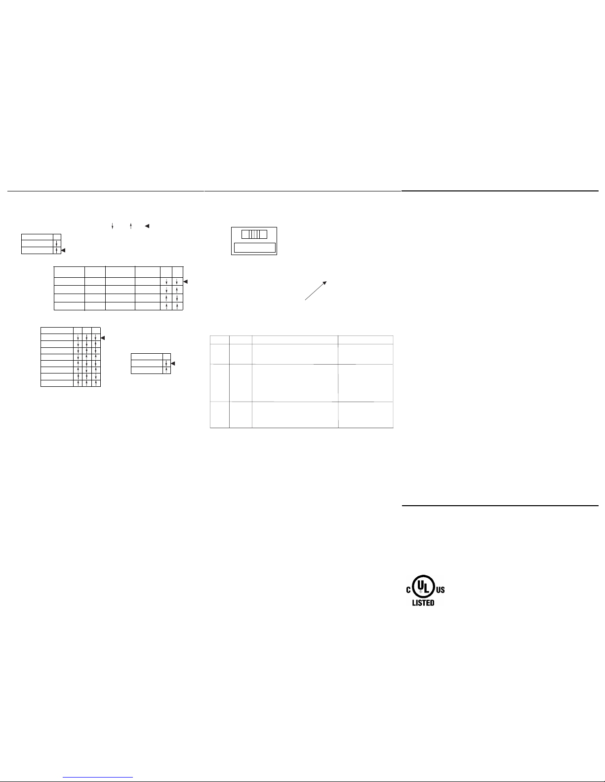
DIP SWITCH SETTINGS
5 Minutes
Walk Through
PIR Sensitivity
50%
100%
Disabled
Enabled
Time Delay
15 Sec/Test
10 Minutes
15 Minutes
20 Minutes
25 Minutes
30 Minutes
1
7
456
The MWOS has 7 DIP switches under
the cover
. They are used
to set
sensitivity, time
delay, trigger
mode, walk through mode feature
settings.
PIR Sensitivity setting: Switch 1
50%, sensor's coverage about 600 square feet. 100%, the maximum range of
sensor's PIR coverage is 1200 square feet, see "coverage pattern".
Trigger Mode: Switches 2, 3
The sensor has 4 trigger options. Use DIP switches 2 & 3 and follow the chart
above for "Trigger Mode":
• Both: requires motion detection by the PIR and the Ultrasonic.
• Either: requires motion detection by only one technology (whichever
detects motion first).
• PIR: requires motion detection only by the PIR.
• US: requires motion detection only by the Ultrasonic.
1 Minute
Trigger Mode
Initial
Trigger Load Output
Maintain
Re-trigger
2
3
Both
Either Either
PIR PIR PIR
Both Both Both
US
Option 1
Option 2
Option 3
Option 4
US
US
Time Delay: Switches 4, 5, 6
The sensor will hold the lights on as long as occupancy is detected based on the
trigger mode selected. The time delay countdown starts when no motion is
detected and the sensor will turn the lights off when the time expires.
Walk-through mode: Switch 7
If no motion is detected within the first 30 seconds after the initial detection, the
sensor will turn the lights off in three minutes. If motion continues beyond the
first 30 seconds, the selected time delay applies.
=Factory Setting=OFF =ON
OCC
Mode
OFF
VAC
Description
Position
Left
Center
Right
Circuit is permanently opened.
(switched off)
Occupancy Mode:
Automatic On, Automatic Off
after selected time delay.
Vacancy Mode: Manual On
only, Automatic Off after
selected time delay.
Push-Button Function
Manually toggles
None
Manually toggles
On / Off the load.
On/Off the load.
Of
f/ Occupancy/
Vacancy Mode Switch
OFF OCC VAC
Push Button
 Loading...