

Enerlites MPC-50H Installation Instructions Manual
1
2
INSTALLATION INSTRUCTIONS
DESCRIPTION
WIRING DIRECTIONS
3
SENSOR ADJUSTMENT
MPC-50H
High Bay 360° Passive Infrared Line Voltage
Occupancy Sensor
SPECIFICATIONS
Adjustable Light Level..................................................10FC—150FC
@ 120VAC, .............................................................0-800W ballast or tungsten
Voltage ...........................................................120/277VAC, 50/60Hz
Load Requirements:
@ 277VAC, ..............................................................................0-1200W ballast
@ 120VAC ...............................................................................................1/4 hp
Adjustable Sensitivity.................................50% or 100%(DIP switch)
Operating Temperature ................................32°to 131°F (0°to 55°C)
Relative Humidity .......................................20-90%, non-condensing
Material........................................................................................ABS
Coverage:
MPC-50H-L1: Mounting height: 50ft Field of view: 360° Coverage :2800 sq.ft
MPC-50H-L2: Mounting height: 8ft Field of view: 360° Coverage :1200 sq.ft
The MPC-50H 360 ° occupancy sensor uses advanced PIR technology to
turn on the lights when motion is detected and keep the lights on when
movement is present. The sensor will automatically turn off the lights if no
movement is detected within the amount of time selected in the time delay.
The MPC-50H is specially designed for use in areas with high ceilings such
as warehouses, distribution centers, and gymnasiums. Be sure to attach the
appropriate lens based on the ceiling height.
There are two lens choices available, lens 1 and lens 2. Lens 1 is an
extended range lens that provides up to 2800 sq. ft. of coverage at a
maximum installation height of 50 ft.
Lens 2 is a high density lens that provides up to 1200 sq. ft. of coverage at a
maximum installation height of 8 ft.
The sensor may be adjusted to operate at the desired level of light under normal
lighting conditions of the immediate area.
To do so, turn the dial to point the arrow toward
the “-”sign for sensor to detect motion and
operate during low light or no light.
Point the arrow toward the “+”sign for
sensor to operate when there’s more light in the
area or even during daylight.
NOTE: The light level is adjustable only when
the time delay is set at or above 30 seconds.
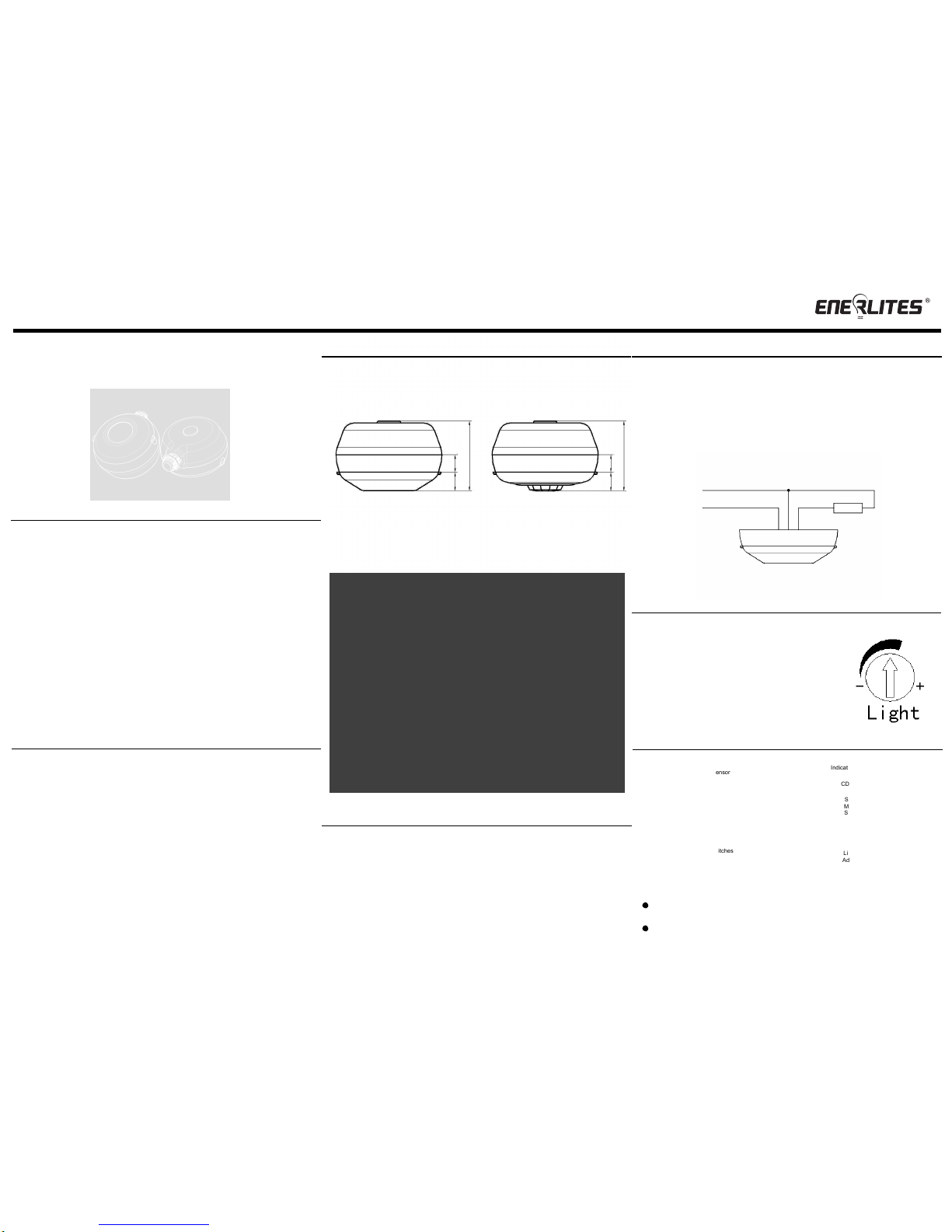
Lens choices:
The coverage area is determined by the type of lens attached to the
MPC-50H. (See Figure 1).
MPC-50H-L1
Extended Range (Lens 1)
MPC-50H-L2
High Density (Lens 2)
0.69"
0.65"
2.60"
0.70" 0.65"
2.61"
WARNING
Turn the POWER OFF at the circuit breaker before installing the
sensor
Read and understand these instructions before installing. This device
is intended for installation in accordance with the National Electric
Code and local regulations. It is recommended that a qualified
electrician performs
this installation. Make sure to turn off the circuit
breaker or fuse(s) and make sure power is off before wiring the
device. Use copper wire only, or equivalent
.
Refer to the wire diagram of the sensor (See Figure 2)
Neutral
Hot
Load
MPC-50H
Black
Red
White
Figure 2
1. Connect the hot wire to the black wire on the sensor
2. Connect the neutral wire to the white wire on the sensor
3. Connect the load wire to the red wire on the sensor
4. If using provided Housing, attach by aligning the arrow
on the MPC-50H with the Open arrow on the Housing,
then twist the device counterclockwise until the Close
arrows align.
5. Turn on Circuit Breaker
If the sensor detects occupancy during the warm-up, the time delay will
increase.
If no occupancy is detected during the warm-up,the light turns OFF after the
initial 60-second warm-up period.
PIR Sensor
Surface
Mounting
Screw Hole
DIP Switches
Detection
Indicator LED
CDS
Light Level
Adjustment
Surface
Mounting
Screw Hole
Note: The LED indicator flashes during the 60-second
warm-up period when power is first applied
COVERAGE
LIGHT LEVEL ADJUSTMENT
Lens 1 at Max 50' high
Lens 2 at 8' high
22' Radius
30' Radius
Figure 1
4
5
6
DIP SWITCH SETTING
TROUBLESHOOTING
INSTALLATION
© 2016 Enerlites Inc.
CA, U.S.A.
0205160002
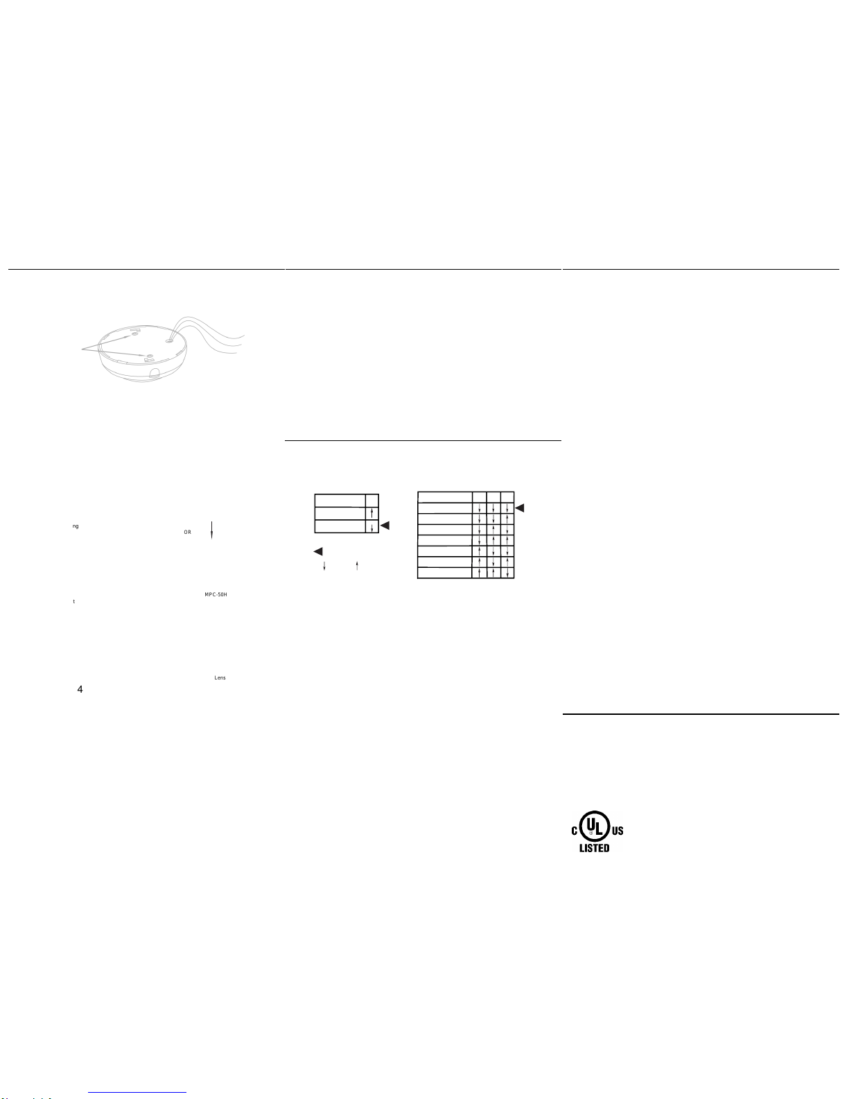
The MPC-50H can be directly attached to the fixture or ceiling (See Figure 3
below), or attached to the fixture or junction box with the provided housing
(See Figure 4 below).
Mounting the Housing
The Housing comes ready to install on the side of a fixture or
junction box.
To mount the Housing on the surface of the fixture or ceiling, twist
off the lock nut on the connector and remove the connector. Then
install it on the back of the Housing and cover the side knockout with
the knockout cover.
Housing
Alignment
Guides
OR
MPC-50H
Lens
Figure 4
Figure 3
Surface mounting
Screw Holes
Connector
The MPC-50H has 4 DIP switches under the lens cover. They are used to
set the sensitivity and time delay. This device is factory preset for quick
installation and is ready to test once installed. After testing, adjust the DIP
switches and Light dial to desired levels.
Time Delay
2
Test/15 Seconds
5 Minutes
10 Minutes
15 Minutes
20 Minutes
25 Minutes
30 Minutes
3
4
Sensitivity
100%
50%
1
Factory setting
=OFF =ON
Sensitivity setting: DIP switch 1
50% -This setting will decrease the amount of area the sensor will cover to
half the range of the installed lens.
100% -This setting will allow the sensor to utilize the maximum range the
installed lens can cover.
Maximum range of MPC-50H-L1 coverage is 2800 square feet. Maximum
range of MPC-50H-L2 coverage is 1200 sq. ft.
Time delay: DIP switch 2,3,4
The time delay is set with Dip switches 2, 3 and 4, from 15 seconds to
30 minutes. When there is no movement detected by sensor, the lights will
automatically turn off after the selected time delay has expired.
Warning:Turn the POWER OFF at the circuit
breaker before installing.
LED does not blink:
1. Make sure the sensor has power.
2. Check the location of the sensor and verify that the sensor
can detect motion from human body. If not , the LED will not
blink.
3. Check the wire connections and verify that the wires are
secured with wire caps.
LED blinks but lights do not turn ON:
1. Check the “Light” setting. If the arrow is pointed to the
“-“position, the area needs to be dark enough for the sensor to
operate. Cover the light sensor lens to simulate darkness. If the
light turns ON, the light level setting needs to be adjusted.
2. Make sure the wires are connected and bulbs are working.
3. Check for obstructions in the lens cover.
4. Make sure that power to the sensor has been ON continuously for
at least one minute. Wait for the warm-up period to end, and if LED
flashes, the load has not turn on, then go to next step.
Lights do not turn OFF automatically:
1. If there is no motion from people or equipment in the sensor’s view but
the LED blinks, look for any nearby source of infrared energy (heat) in
motion, such as turbulent air from a heating or cooling supply.
• Mount the sensor so that it’s lens is below the edge of the fixture
and does not directly view the lamps.
• Move the air supply away from the sensor, or move the sensor.
2. Verify the time delay settings in switches 2-4. The time delay can be set
from 15 seconds to 30 minutes. Ensure that the time delay is set to the
desired delay and that there is no movement within the sensor’s view for
that time period.
3. Check sensor wire connections, verify load and neutral wires are
secure.
TESTING OCCUPANCY SENSOR
Note: There is a 40- second warm-up period when power is first applied. Use
a small screwdriver to open the front cover and make changes to the settings.
The pre-set time delay is Test mode and light level is set at maximum
Refer to Figure 3 on previous page.
1. Ensure the PIR Activity is enabled, red LED flashes, and PIR Sensitivity
is set to 100% (DIP switch 1 OFF).
2. Ensure the Time Delay is set for Test Mode.
3. Ensure that the Light Level is at the maximum position.(see" LIGHT
LEVEL ADJUSTMENT”).
4.
5.
Remain still. The red LED should not flash. The lights should turn off
after 15 seconds. (If not, see “TROUBLESHOOTING.”)
Move in the front of coverage area. The lights should turn on
automatically. When functional test is complete, set DIP Switches,
Time Delay and Light Level to the desired settings, and put the front
cover back on the sensor.
WARRANTY INFORMATION
This device is warranted to be free of material and workmanship defects for 2 years from the
date of purchase. Original receipt or proof of purchase from an authorized retailer must be
presented upon warranty claim. ALL claims must be verified and approved by Enerlites, Inc.
Warranties from other Enerlites products may vary. This warranty is nontransferable and
does not cover normal wear and tear or any malfunction, failure, or defect resulting from
misuse, abuse, neglect, alteration, modification, or improper installation. To the fullest extent
permitted by the applicable state law, Enerlites shall not be liable to the purchaser or end
user customer of Enerlites products for direct, indirect, incidental, or consequential damages
even if Enerlites has been advised of the possibility of such damages. Enerlites’ total liability
under this or any other warranty, express or implied, is limited to repair, replacement or
refund. Repair, replacement or refund are the sole and exclusive remedies for breach of
warranty or any other legal theory.
 Loading...