

Page 1

EDP70 PLUS
UNINTERRUPTIBLE POWER SYSTEM
24/36/50/80kVA –
3 phase input / 3 phase output
USER HANDBOOK
PART NUMBER 10H52152PU9C rev.1
Page 2

IMPORTANT SAFETY INSTRUCTIONS
READ BEFORE INSTALLING
1) SAVE THESE INSTRUCTIONS
This manual contains important instructions for the EDP70 PLUS which should be followed during
installation and maintenance of the UPS and associated batteries.
2) The installation must be inspected by trained technicians.
The instructions must be followed.
3) When external batteries are provided by the Customer and not Chloride, reference must be made
to
the installation instructions provided by the battery supplier.
WARNINGS
1) The AC and DC supplies to the EDP70 PLUS UPS and the AC output from the UPS MUST be fed
through suitably rated circuit breakers or fuses and isolating switches suitable for branch circuit
operation.
2) Any external battery cabinet connected to the UPS MUST be provided with an over-current
protection device per UL1778 Par. No. 10.4
3) To reduce the risk of fire or electric shock, the equipment must be installed indoors, in a humidity
and temperature controlled environment which is free from conductive contaminants.
SAFETY
1) DO NOT REMOVE COVERS DURING NORMAL OPERATION. The panels will be removed
during installation, however this should only be undertaken by qualified technicians. It should be
ensured
that the UPS is switched off and that all power sources are disconnected (A.C. mains and Battery)
before either the rear or side panels are removed.
2) FOREIGN OBJECTS MUST NOT BE INTRODUCED INTO THE VENTILLATION GRILLES.
HAZARDOUS VOLTAGES are present within the EDP70 PLUS even when it is switched off.
3) Fuses must ONLY be replaced with the same type and rating.
4) The EDP70 PLUS contains a battery which can be DANGEROUS if interfered with. Contact the
supplier for replacement.
5) The UPS and/or its components must be disposed of as notifiable waste in accordance with local
pollution control (special waste) regulations.
page 2 -- MI00/10056 rev.1--05/2001
Page 3
WARNING
The UPS contains hazardous voltages, even when all switches are open.
In case of fire in the installation area, do not use water to extinguish fire.
ELECTRICAL PRECAUTIONS:
If the UPS is in By-pass mode and the Output switch is closed, no indications will be
displayed; fans will however function, and hazardous voltages are present downline
from the static switches.
EMERGENCY PROCEDURE
In the case of an emergency, the load supply can be interrupted by switching off all the
switches fitted in the UPS.
ELECTRIC SHOCK
Switch off power; use dry insulating material for protection when pulling the injured person
clear of conductors.
NEVER TOUCH THE INJURED PERSON WITH BARE HANDS UNTIL CLEAR OF
CONDUCTORS. SEEK QUALIFIED ASSISTANCE IMMEDIATELY.
INJURIES CAUSED BY CONTACT WITH CORROSIVE LIQUIDS
In normal conditions, installed batteries are sealed. A damaged battery container may
however leak electrolyte, or cause the latter to come into contact with battery parts.
In the event of electrolyte contact with the eyes, rinse eyes thoroughly with a saline solution
or fresh water for at least 10 minutes.
In the event of electrolyte contact with skin, rinse the affected area with abundant water.
Remove contaminated clothing. Cover affected area with dry gauze.
If electrolyte is swallowed, do not induce vomiting. Administer large quantities of
milk or water.
IN ALL CASES, SEEK MEDICAL ATTENTION IMMEDIATELY
MI00/10056 rev.1--05/2001-- page 3
Page 4

Contents
1.0 INTRODUCTION................................................................................................................6
1.1 Summary of the manual................................................................................................6
1.2 Summary of the equipment ..........................................................................................6
1.3 Block diagram................................................................................................................6
1.4 Functions.......................................................................................................................8
1.5 Operational modes........................................................................................................9
2.0 SAFETY...........................................................................................................................11
2.1 General safety..............................................................................................................11
2.2 Symbols .......................................................................................................................11
2.3 Electrical precautions ................................................................................................. 12
2.4 Battery precautions.....................................................................................................12
2.5 Battery safety equipment............................................................................................12
3.0 STORAGE .......................................................................................................................13
4.0 INSTALLATION...............................................................................................................13
4.1 Mechanical characteristics.........................................................................................13
4.2 Installation ...................................................................................................................21
Recommended wire sizes....................................................................................................22
4.4 Ventilation.................................................................................................................... 24
5.0 CONNECTION.................................................................................................................25
5.1 Electrical connections.................................................................................................28
5.2 24 – 12/18/24kVA..........................................................................................................29
5.3 36 – 24/30/36kVA..........................................................................................................32
5.3 EDP70 PLUS 50/80kVA................................................................................................35
5.4 Signal connections......................................................................................................38
6.0 CONTROLS.....................................................................................................................39
6.1 User Controls...............................................................................................................39
6.2 Control Panel...............................................................................................................40
7.0 START UP .......................................................................................................................41
page 4 -- MI00/10056 rev.1--05/2001
Page 5

Figures
Figure 1 – Block diagrams – 24/36kVA....................................................................................7
Figure 2 – Block diagram – 50/80kVA......................................................................................8
Figure 3 – Normal operation.....................................................................................................9
Figure 4 – Utility Supply failure................................................................................................9
Figure 5 – Re-establishing the Utility Supply........................................................................10
Figure 6 – Transferring the Load onto the Reserve Supply.................................................10
Figure 7 – 24 Footprint and cabinet dimensions ..................................................................14
Figure 8 – 36 Footprint and cabinet dimensions ..................................................................15
Figure 9 – 50/80 Footprint and cabinet dimensions .............................................................16
Figure 10 – “A” Battery Cabinet Drawing for 24/36kVA Ratings..........................................17
Figure 11 – “B” Battery Cabinet Drawing for 24/36kVA Ratings..........................................18
Figure 12 – “E” Battery Cabinet Drawing for 50/80kVA Ratings..........................................19
Figure 13 – “F” Battery Cabinet Drawing for 50/80kVA Ratings..........................................20
Figure 14 – UPS Ratings.........................................................................................................21
Figure 15 – Connection diagrams..........................................................................................25
Figure 16 - 24 – 12/18/24kVA: Switches and Breakers .........................................................29
Figure 17 - 24 – 12/18/24kVA: Switches.................................................................................30
Figure 18 - 24 – 12/18/24kVA: Cable Connections................................................................31
Figure 19 - 36 – 24/30/36kVA: Switches and Breakers .........................................................32
Figure 20 - 36 – 24/30/36kVA: Connections...........................................................................33
Figure 21 - 36 – 24/30/36kVA: Cable Connections................................................................34
Figure 22 – 50/80kVA: Switches and Breakers .....................................................................35
Figure 23 – 50/80kVA: Connections.......................................................................................36
Figure 24 – 50/80kVA: Cable Connections............................................................................37
Figure 25 – Control panel .......................................................................................................39
MI00/10056 rev.1--05/2001-- page 5
Page 6

1.0 INTRODUCTION
1.1 Summary of the manual
This handbook provides for the safe installation, startup and use of the EDP70 PLUS Uninterruptible Power
System (UPS). The Company recommends that the equipment be installed and regularly maintained by a
Chloride Authorized personnel.
DO: - read the User Handbook before operating the EDP70 PLUS UPS.
- keep a log of all incidents.
- protect the batteries from damage. Batteries leak acid; avoid contact with skin,
clothes or eyes.
DO NOT: - operate the control switches.
- operate the EDP70 PLUS UPS with any covers removed.
- obstruct the ventilation grilles.
1.2 Summary of the equipment
The EDP70 PLUS Uninterruptible Power System (UPS) totally isolates the load from voltage drops, spikes,
transients frequency variations in the utility supply.
In the event of failure or brownout of the AC utility supply, an internal audible alarm sounds and an LED on the
control panel illuminates, the EDP70 PLUS UPS will continue to provide safe, clean continuous power, without
interruption, from the battery, for a duration dependent on battery capacity and output load.
The audible alarm alerts the user to start a safe orderly shutdown of the load. When the AC utility supply returns to
normal, the EDP70 PLUS UPS automatically recharges the battery ready for any future power failure.
The microprocessor display panel provides access to very detailed information regarding the status of the supplies
and EDP70 PLUS UPS. Refer to current publication for detailed specification.
The block diagram, shows the main functional sub-assemblies of the EDP70 PLUS UPS. The AC three phase
utility supply is rectified to provide direct current, which maintains the battery in a fully charged state and also
supplies the inverter, which provides the three phase output via an electronic static switch.
Normally the supply of the reserve line is taken from the AC utility input, but special units, with a separate reserve
input supply, are available. This allows the inputs to be supplied from independent three phase sources.
Provided the reserve supply is within limits, the inverter will match the output frequency with the reserve supply
frequency. The inverter has its own internal crystal control to stabilize the output frequency if the reserve supply
frequency is out of limits. The electronic static switch switches the output from the inverter to the reserve supply,
without interruption, to meet any load current surges, or to supply the load if the battery is discharged during an AC
utility supply failure.
Maintenance and testing can be carried out on the EDP70 PLUS UPS without interrupting the output, by switching
the load from the reserve supply to the maintenance bypass circuit. This work should only be carried out by
Chloride-trained personnel.
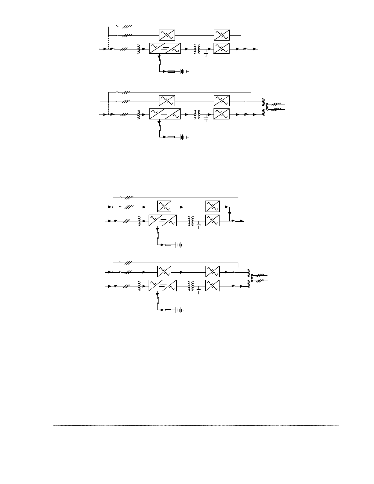
1.3 Block diagram
page 6 -- MI00/10056 rev.1--05/2001
Page 7
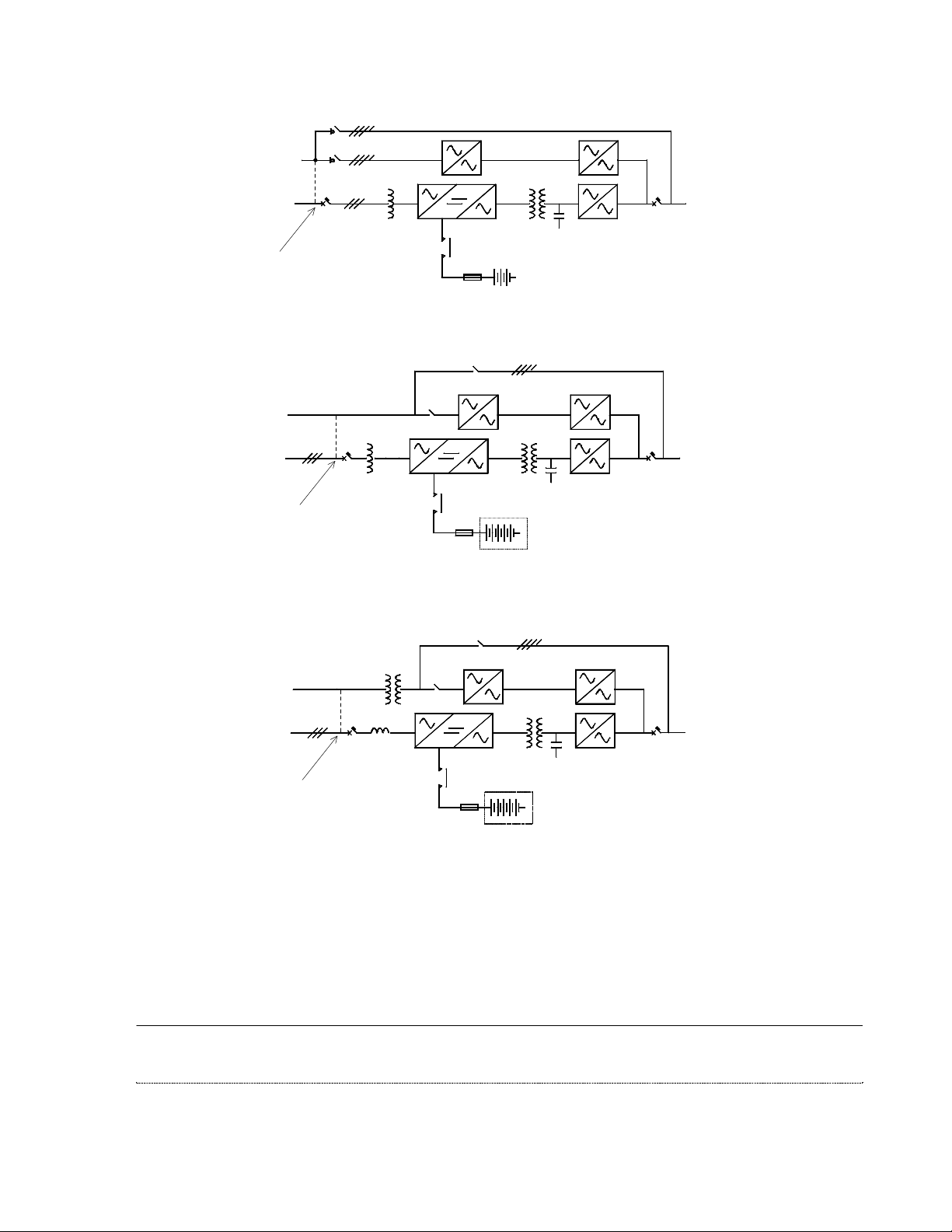
24kVA - STANDARD CONFIGURATION
S3
Reserve Supply
208Y/120V
S2
S1
AC Supply
IN THE ABSENCE OF A SEPARATE RESERVE
SUPPLY THE RESRVE IS DERIVED FROM THE
AC UTILITY INPUT WITH THE JUMPER
CONNECTED AS INDICATED
Reserve Supply
208Y
S1
AC Supply
IN THE ABSENCE OF A SEPARATE RESERVE
SUPPLY THE RESRVE IS DERIVED FROM THE
AC UTILITY INPUT WITH THE JUMPER
CONNECTED AS INDICATED
Maintenance By-pass
290
3
Battery
Contactor
208150
1
5
4
144 Cells
(Internal)
2
36kVA - STANDARD CONFIGURATION
480
208Y
S2
S3
Battery
Contactor
250
1
3
Maintenance By-pass
5
208Y
4
240 Cells
(External)
2
S4
S4
Reserve Supply
480V
S1
AC Supply
IN THE ABSENCE OF A SEPARATE RESERVE
SUPPLY THE RESRVE IS DERIVED FROM THE
AC UTILITY INPUT WITH THE JUMPER
CONNECTED AS INDICATED
Figure 1 – Block diagrams – 24/36kVA
36kVA - 480V/208V CONFIGURATION
480
208Y
S2
S3
Battery
Contactor
250
1
Maintenance By-pass
3
208Y
240 Cells
(External)
5
4
2
MI00/10056 rev.1--05/2001-- page 7
S4
Page 8
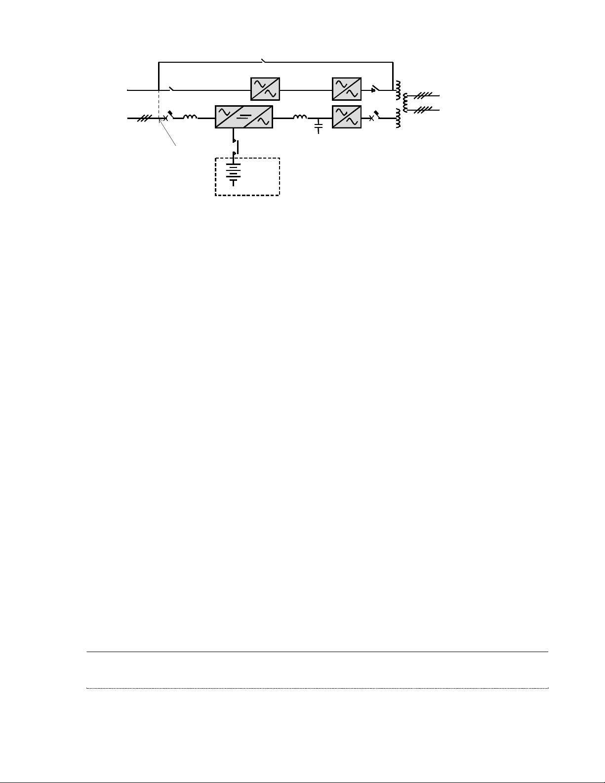
S3
Maintenance Bypass
Reserve
Supply
480V
AC Supply
S2
S1
IN THE ABSENCE OF A SEPARATE
RESERVE SUPPLY THE RESERVE IS
DERIVED FROM THE AC UTILITY
INPUT WITH THE JUMPER
CONNECTED AS INDICATED
Battery
Contactor
240 Cells
(External)
3
1
2
S5
5
S4
4
480Y/277V
208Y/120V
Figure 2 – Block diagram – 50/80kVA
The uninterruptible power system consists of the following:
1 - RECTIFIER/INVERTER S1 = Equipment ON/OFF switch
2 - BATTERY S2 = Equipment Reserve switch
3 - BACKFEED PROTECTION S3 = Equipment By-pass switch
4 - INVERTER STATIC SWITCH S4 = Equipment OUTPUT switch
5 - RESERVE STATIC SWITCH (INVERTER OUTPUT switch for 50/80kVA only)
S5 = RESERVE OUTPUT switch for 50/80kVA only
1.4 Functions
RECTIFIER / BATTERY CHARGER
The rectifier/battery charger transforms the alternating current of the mains supply to direct voltage to maintain the
battery in a fully charged state and also supply the inverter.
BATTERY
The battery is an energy reserve that is used by the inverter and the load whenever the mains supply fails.
INVERTER
The inverter changes the direct voltage from the rectifier or from the battery into a three phase sinusoidal
alternating voltage for the external supply.
ELECTRONIC STATIC SWITCH
The function of the electronic static switch is to select one of the two sources of alternating voltage and to supply it
to the external load. The two sources of voltage supplied to the static switch are the output of the inverter and the
reserve supply. In normal working conditions, the static switch supplies the load from the inverter.
SWITCHES
The switches permits maintenance and repair of the UPS, without interrupting the supply to the load.
page 8 -- MI00/10056 rev.1--05/2001
Page 9
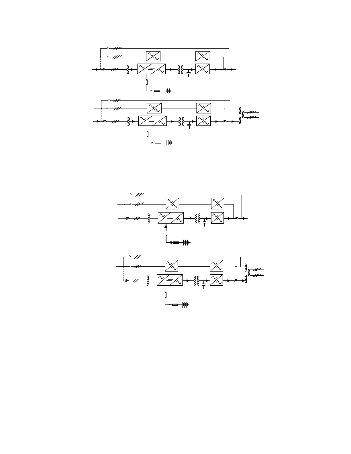
1.5 Operational modes
S3
S2
Maintenance By-pass
AC Supply
AC Supply
S1
Battery
Contactor
S3
S2
S1
Battery
Contactor
24/36kVA Ratings
Maintenance By-pass
50/80kVA Ratings
LOAD
S4
S5
S4
480Y/277V
LOAD
208Y/120V
Figure 3 – Normal operation
During normal operation the load is supplied by the mains through the rectifier and inverter. The rectifier also
supplies the current for recharging and maintaining the battery in a fully charged state.
Reserve Supply
AC Supply
S3
S2
S1
Battery
Contactor
Maintenance By-pass
24/36kVA Ratings
S4
LOAD
Reserve Supply
AC Supply
S3
S2
S1
Battery
Contactor
Maintenance By-pass
S5
S4
50/80kVA Ratings
480Y/277V
LOAD
208Y/120V
Figure 4 – Utility Supply failure
When the utility supply voltage is absent or outside the allowed tolerances, the battery supplies the inverter. This
will be indicated on the UPS front panel display and the Remote Alarm Unit (if fitted). The standby time available
depends both on the capacity of the battery and on the size of load. It is possible to extend autonomy by reducing
the output power by disconnecting non-important loads. In all cases, the alphanumerical display shows the residual
autonomy.
MI00/10056 rev.1--05/2001-- page 9
Page 10
Reserve Supply
S3
S2
Maintenance By-pass
S4
S5
S4
480Y/277V
208Y/120V
AC Supply
Reserve Supply
AC Supply
S1
Battery
Contactor
S3
S2
S1
Battery
Contactor
24/36kVA Ratings
Maintenance By-pass
50/80kVA Ratings
Figure 5 – Re-establishing the Utility Supply
When the utility supply returns within acceptable limits, the UPS returns automatically to normal operation mode as
previously described. The rectifier now starts to recharge the battery. However, until recharge has been
completed, any further mains failure will result in reduced standby times.
Reserve Supply
AC Supply
S3
S2
S1
Battery
Contactor
Maintenance By-pass
S4
24/36kVA Ratings
Reserve Supply
AC Supply
S3
S2
S1
Battery
Contactor
Maintenance By-pass
50/80kVA Ratings
S5
S4
480Y/277V
208Y/120V
Figure 6 – Transferring the Load onto the Reserve Supply
Transfer onto the reserve line is caused by two conditions:
a) inverter stop
b) overload
In both instances the load is transferred onto the reserve without interruption. If the overload is temporary, the
system will re-transfer from reserve to inverter as soon as the it ceases. This allows for the initial start-up of loads
with high or excessive switch-on currents.
page 10 -- MI00/10056 rev.1--05/2001
Page 11
2.0 SAFETY
Read all instructions carefully before installing or operating the equipment.
2.1 General safety
The procedure described in these instructions is intended for use by persons experienced in the operation of
Uninterruptible Power Systems and ancillary equipment.
Persons unfamiliar with this type of equipment should seek guidance from experienced personnel.
The EDP70 PLUS UPS is designed to be operated in accordance with existing safe operating procedures.
These instructions are not intended to replace existing safety practices.
If there are any questions regarding the safe operation of the system, contact a Chloride service representative.
This equipment is designed and built for safe operation when used to supply its rated load, providing it is installed
as specified by qualified, licensed and competent electricians.
Electrical energy can be supplied by the equipment and the battery.
2.2 Symbols
The following symbols appear in this book and in the unit:
Warning - Hazardous voltages are present. If the instructions are not heeded, there is a
risk of electrical shock and danger to personal safety.
DIRECT CURRENT SUPPLY
ALTERNATING CURRENT SUPPLY
ON position of the switches
OFF position of the switches
Inverter Start Up
Inverter Shutdown
Audible Alarm Cancel Switch
For explanation see Para. 6.2. of this
manual
For explanation see Para. 6.2. of this
manual
For explanation see Para. 6.2. of this
manual
MI00/10056 rev.1--05/2001-- page 11
Page 12

Page Right Control For explanation see Para. 6.2. of this
manual
Record Up For explanation see Para. 6.2. of this
manual
Record Down For explanation see Para. 6.2. of this
manual
2.3 Electrical precautions
Never handle a component or assembly without first confirming that no voltage is applied or present. Remove only
those protective covers that are essential to perform the repairs or adjustment currently required, and replace them
as soon as possible.
. Use only insulated tools.
. Place a rubber insulating mat in front of all equipment doors.
. Keep all door closed and locked at all times during normal operation.
2.4 Battery precautions
Always isolate the load before connecting or disconnecting the batteries or battery cells.
Ensure that batteries are fully isolated by disconnecting the battery connectors, opening circuit breakers, or both.
Remove all jewellery from hands, wrists and neck before working on batteries or battery cells.
Before leaning over batteries, remove any metal object that could fall out of pockets.
Do not place tools or other conductive objects on the batteries.
2.5 Battery safety equipment
When working on or handling batteries, ensure that the following items are worn:
. Eye goggles
. Rubber gloves
. Rubber apron
. Rubber boots
When batteries are being moved or worked on, ensure the following items are available in the immediate vicinity:
. An eye bath, eyewash station or equivalent
. A clean water source to wash spilled acids
. Absorbent materials to soak up spilled acids
. Disposal for contaminated materials.
page 12 -- MI00/10056 rev.1--05/2001
Page 13

3.0 STORAGE
If the EDP70 PLUS UPS cannot be installed within sixty days of delivery, there is a danger of the integral
battery becoming discharged thereby sustaining permanent damage and affecting the standby period available
and battery life. The date the battery was last recharged and the date the battery is due for its next recharge are
both stamped on the packaging accompanying the unit. If you intend to store the unit, please refer to the recharge
date.
When the EDP70 PLUS is due to be recharged, refer to the Installation instructions and connect the EDP70 PLUS
UPS to a temporary AC supply. The battery MUST be recharged for at least 24 hours every 3 months.
4.0 INSTALLATION
4.1 Mechanical characteristics
- Ambient temperature 18°F[-10°C] to 104°F [+40°C ]
- Relative Humidity (w/out condensing @ 68°F[20°C]) < 90%
- Max altitude (w/out derating) 3300 feet [1000 m] above sea-level
- Protection degree (panel fitted)
- Input cables bottom
- Air inlet bottom
- Air outlet rear
UPS model
Description
Size width
depth
height
u.m.
In
[mm]
24 36 50 80
27.5 [700]
28.7 [730]
56 [1420]
27.5 [700]
28.7 [730]
56 [1420]
35.4 [900]
28.7 [730]
63 [1600]
35.4 [900]
28.7 [730]
63 [1600]
Total
Weight
(UPS +
Battery)
Floor Area
Floor
Loading
(UPS +
Battery)
Acoustic Noise
100% Linear Load
Air-Flow
w/out cells
25 Ah cells
30 Ah cells
35 Ah cells
w/out cells
25 Ah cells
30 Ah cells
35 Ah cells
Lbs
[kg]
In2[m2] 789 [0.511] 789 [0.511] 1019 [0.657] 1019 [0.657]
2
Lbs/in
[kg/m2]
cfm
[mc/h]
dBA 52 55
Notes: 1) n.a. = not applicable
2) Longer autonomies, and battery for EDP above 20 kVA are available with external
battery cubicles.
880 [400]
1342 [610]
1456 [662]
1526 [694]
1.12 [782]
1.70 [1194]
1.85 [1296]
1.93 [1358]
235
[400]
1300 [590]
n.a.
n.a.
n.a.
1.65 [1155]
n.a.
n.a.
n.a.
647
[1100]
1342 [610]
n.a.
n.a.
n.a.
1.32 [930]
n.a.
n.a.
n.a.
MI00/10056 rev.1--05/2001-- page 13
1800 [818]
n.a.
n.a.
n.a.
1.77 [1245]
n.a.
n.a.
n.a.
Page 14
1417,0
(26.77)
680,0
ALL MEASUREMENTS ARE IN
MILLIMETERS (AND INCHES)
700,0 (27.56)
(55.79)
645,0
(25.39)
30,0
(1.18)
726,0 (28.58)
58,0 (2.28)
NR 4 X
260 (10.24) X 66 (2.6)
CABLE ENTRY
ø
8
(
ø
0
,
3
1
)
(2.64)
67,0
728,0 (28.66)
600,0
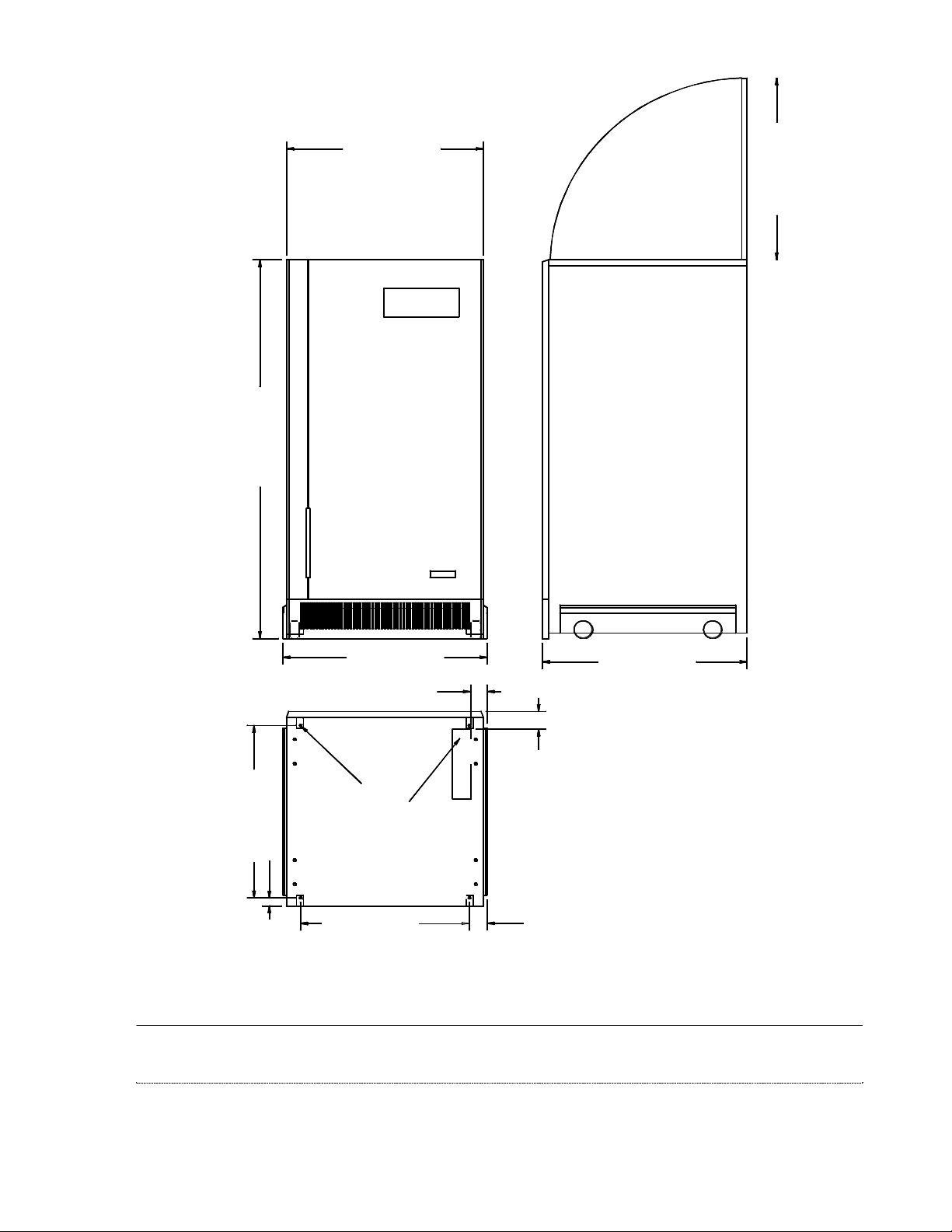
Figure 7 – 24 Footprint and cabinet dimensions
page 14 -- MI00/10056 rev.1--05/2001
(23.62)
63,0 (2.48)
Page 15
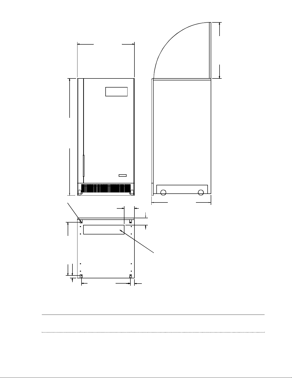
ALL MEASUREMENTS ARE IN
(26.77)
680,0
MILLIMETERS (AND INCHES)
700,0 (27.56)
1417,0
(55.79)
NR 4 X
ø
8
(
ø
0
,
3
1
)
645,0
30,0
(25.39)
(1.18)
125,0
(4.92)
88,0
(3.46)
CABLE ENTRY
500 (19.68) X 110 (4.33)
(28.66)728,0
600,0
(23.62)
50,0
(1.97)
Figure 8 – 36 Footprint and cabinet dimensions
MI00/10056 rev.1--05/2001-- page 15
Page 16
ALL MEASUREMENTS ARE IN
MILLIMETERS (AND INCHES)
900,0 (35.43)
1600
(63.0)
NR 4 X
ø
8
(
ø
0
,
3
1
)
645,0
(25.39)
30,0
(1.18)
100,0
800,0
(3.94)
(31.5)
Figure 9 – 50/80 Footprint and cabinet dimensions
page 16 -- MI00/10056 rev.1--05/2001
68,0
(2.68)
700 (27.56) X 110 (4.33)
CABLE ENTRY
50,0
(1.97)
740,0 (29.13)
Page 17
Figure 10 – “A” Battery Cabinet Drawing for 24/36kVA Ratings
MI00/10056 rev.1--05/2001-- page 17
Page 18
Figure 11 – “B” Battery Cabinet Drawing for 24/36kVA Ratings
page 18 -- MI00/10056 rev.1--05/2001
Page 19

Figure 12 – “E” Battery Cabinet Drawing for 50/80kVA Ratings
MI00/10056 rev.1--05/2001-- page 19
Page 20
Figure 13 – “F” Battery Cabinet Drawing for 50/80kVA Ratings
page 20 -- MI00/10056 rev.1--05/2001
Page 21

4.2 Installation
Check the rating label on the rear of the front panel of the EDP70 PLUS UPS to ensure the input/output voltages,
frequency and load are all within the rating of the UPS.
EDP70 PLUS is designed to operate in an office environment with an optimum temperature of 68°F [20 C].
A gap of at least 4In [ 10cm. ] must be maintained at rear of the UPS to ensure adequate ventilation.
Nothing should be placed around the equipment which might restrict the airflow.
Ensure the interconnecting cables do not cause a hazard to the user.
A gap of at least 32 In [ 800 mm] must be maintained above the UPS to ensure adequate space for maintenance.
The appropriate lifting equipment must be used to move the EDP70 PLUS UPS.
Figure 14 – UPS Ratings
UPS ratings
Description
Output power
Nominal Load
Maximum input power (with
unit @ nominal Load &
battery recharge)
Maximum dissipation (with
inverter @ nominal Load)
Number of battery cells
Battery voltage range
Battery
end-discharge current
U.M.
kVA 12 18 24 24 30 36
kW 8 12 16 16 20 24
kVA 15 21 28 28 35 42
BTU/H 3750 5460 6800 7700 9500 11300
n 144 240
V 238-327 396-545
A 37 55 74 53 67 80
24
12kVA2418kVA2424kVA3624kVA3630kVA3636kVA
Description
Output power
Nominal Load
Maximum input power (with
unit @ nominal Load &
battery recharge)
Maximum dissipation (with
inverter @ nominal Load)
Number of battery cells
Battery voltage range
Battery
end-discharge current
UPS ratings
U.M.
kVA 30 40 50 50 65 80
kW 24 32 40 40 52 64
kVA 43 57 71 71 91 112
BTU/H 14300 14300 18600 22100
n 240
V 396-545
A 67 88 110 105 140 173
50
30kVA5040kVA5050kVA8050kVA8065kVA8080kVA
MI00/10056 rev.1--05/2001-- page 21
Page 22

Recommended wire sizes
1) It is recommended that the external cables and protection be selected for the highest
rated unit of the model in use.
2) Reserve (or primary) input and output Neutral cable size should be greater than that of
the line cables in order to be able to supply non-linear loads having a Crest Factor of up to
3:1 (i.e. where neutral current = 1.7 x line current).
If non-linear loads are not to be supplied from the Installation, the Neutral can be of the same
size as the load cable.
3) Recommended AC input overcurrent protection represents 125% of nominal full load
current (continuous) plus the short duration input current (non-continuous) for battery recharging per NEC 220-10 b.
4) UPS output cables should be run in separate conduits from input cables.
5) Grounding conductors are sized per NEC 250-95.
6) Cable sizes are based upon NEC.
Recommended sizes only. Be sure to follow the codes which apply to your
installation.
Refer to UPS connection data table on following page.
page 22 -- MI00/10056 rev.1--05/2001
Page 23

UPS Type
Vin/V
out
A.C. Supply Reserve Supply
Rated
current
(A)
Protection
device
(A)
Output
Nominal
current
(A)
Nominal
current
(A)
Protection
device
(A)
24/12kVA
24/18kVA
24/24kVA
36/24kVA
36/30kVA
36/36kVA
36/24kVA
36/30kVA
36/36kVA
50/30kVA
50/40kVA
50/50kVA
50/30kVA
50/40kVA
208/208
208/208
480/208
480/480
480/208
42 50 33 33 50
60 80 50 50 75
78 100 67 67 100
78 100 67 67 100
97 100 83 83 125
118 125 100 100 150
34 45 67 30 45
42 50 83 36 55
51 70 100 43 65
50 70 36 36 50
66 90 48 48 80
83 110 60 60 80
50 70 83 36 50
66 90 111 48 80
50/50kVA
80/50kVA
80/65kVA
80/80kVA
80/50kVA
80/65kVA
80/80kVA
480/480
480/208
83 110 139 60 80
83 110 60 60 80
110 125 78 78 100
135 150 96 96 125
83 110 139 60 80
110 125 180 78 100
135 150 222 96 125
MI00/10056 rev.1--05/2001-- page 23
Page 24

4.4 Ventilation
UPS can work in a continuous environment within 18°F[-10°C] to 104°F [+40°C ] temperature range, although,
ideally the ambient temperature should be below 78°F [25°C].
The heat, dissipated by the UPS (indicated on figure 7), is extracted by internal fans and then dissipated into the
air.
The heat can be removed from the UPS room by a forced cooling ventilation system or, alternatively, an air
conditioning system.
The required air changes per hour will depend on the UPS rating and this heat loss and on the cooling air
temperature.
To calculate the required air flow for the dissipated power, the altitude and the cooling air temperature, the
following equation can be used:
• P
V = 2770 - - - - - - • e
with: V = air flow [mc/h]
P
= total dissipated power [kW]
d
T
= max. temperature allowed into the room [104°F = 40°C = 313°K]
r
T
= Temperature of input cooling air
k
T
= 273 °K
0
h = altitude above the sea level [km]
d
Tr - T
(0.125 h Tk / T0 )
k
page 24 -- MI00/10056 rev.1--05/2001
Page 25

5.0 CONNECTION
Protection devices to be installed by the customer
according to the information shown on page 23
UTILITY
INPUT
RESERVE
INPUT
UTILITY
INPUT
L1
L2
L3
N
Neutral not
present on
50 and 80kVA
ratings
L1
L2
L3
N
L1
L2
L3
A
B
C
A
B
C
N
G
N
1
Remove link to connect remote E.P.O.
2
3
Battery Charge Inhibit
4
5
Thermostick contacts
6
GROUND
Protection devices to be installed by the customer
according to the information shown on page 23
A
B
C
Neutral not
N
present on
50 and 80kVA
ratings
A
B
C
G
A
B
C
N
1
Remove link to connect remote E.P.O.
2
3
Battery Charge Inhibit
4
5
Thermostick contacts
6
L1
L2
OUTPUT
L3
N
(Neutral separately derived
on 50 and 80kVA ratings)
EXTERNAL
BATTERIES
L1
L2
OUTPUT
L3
N
(Neutral separately derived
on 50 and 80kVA ratings)
EXTERNAL
BATTERIES
GROUND
Figure 15 – Connection diagrams
THE AC AND DC SUPPLIES TO THE EDP70 PLUS UPS, AND THE AC OUTPUT FROM THE UPS, SHOULD BE FED
THROUGH SUITABLY RATED CIRCUIT BREAKER OR FUSE(S) AND ISOLATING SWITCH SUITABLE FOR BRANCH
CIRCUIT PROTECTION.
NOTE: INTERRUPTING THE NEUTRAL FEED MAY CAUSE THE CHANGE IN GROUND-NEUTRAL VOLTAGE TO
NOTE: ALL CIRCUIT BREAKERS OR FUSES AND ISOLATING SWITCHES SHOULD BE FITTED AS CLOSE TO THE
AFFECT THE LOAD.
EDP70 PLUS UPS AS POSSIBLE AND MARKED WITH THE LABELS PROVIDED WITH THE UNIT.
IT IS ALSO RECOMMENDED A LABEL AS FOLLOWS
MI00/10056 rev.1--05/2001-- page 25
Page 26

UNINTERRUPTIBLE POWER SYSTEM
NO UNAUTHORIZED OPERATION
page 26 -- MI00/10056 rev.1--05/2001
Page 27

CAUTION!
In maintenance by-pass operation,
All power connection must carried out by qualified
licensed personnel experienced
in wiring this type of equipment
The safety ground wire must
be connected before the power input cables
The correct phase rotation
(phase A leads B leads C)
must be observed on the UPS terminals.
An input grounded neutral conductor is required
(24/36kVA only)
the UPS components are de-energized,
with the exception of input/output terminals,
battery cabinet, input matching voltage
transformer (for 480/208 configuration) and isolating
transformer (for 50 and 80kVA).
All input power (AC and DC) must be disconnected to ensure
WARNING!
complete isolation
MI00/10056 rev.1--05/2001-- page 27
Page 28

5.1 Electrical connections
WARNING!
All electrical connections must
be made by a qualified electrician
and meet local electrical code standards
Before attempting to connect the mains supply, the reserve/bypass supply or the load, ensure that all supplies,
including the battery, are isolated and that all the equipment switches are in their »OFF» position.
Open UPS front access panel and remove internal panel over main switches and terminal blocks.
NOTES: 1)In accordance with para. 12.7 of UL 1778, the installation must be performed by a qualified
electrician. The terminals require the use of the proper crimp tools and terminals in order to
perform an installation in accordance with the National Electrical Code (NEC).
The recommended crimp tools, terminals and torque are shown in the followings tables:
2)Use Copper Conductors Only
Table of T& B’s cat.no.s for terminals and crimp tools
page 28 -- MI00/10056 rev.1--05/2001
Page 29

5.2 24 – 12/18/24kVA
Ensure the AC supplies and load are switched OFF. Check that all the EDP70 PLUS UPS Switches (behind the
front panel) are switched OFF, see Figure 16 .
The AC supply cables must be suitable for carrying the maximum supply demand. The voltage drop in the cable
should be minimized to ensure the AC supply voltage at the EDP70 PLUS UPS terminals is within +/- 10% of
nominal.
The EDP70 PLUS UPS should be connected to the main/reserve supplies and output load via a wall mounted
junction box.
Installation and connection should only be carried out by qualified electrical personnel.
S2 = Equipment Reserve Switch
S1 = Equipment ON/OFF Breaker
S3 = Equipment By-pass Switch
S4 = Equipment OUTPUT Breaker
Battery Compartment
Figure 16 - 24 – 12/18/24kVA: Switches and Breakers
MI00/10056 rev.1--05/2001-- page 29
Page 30

Output, Reserve, Input
and External Battery Terminals
Hinged panel security screws
Cable support
Cable channel
Figure 17 - 24 – 12/18/24kVA: Switches
Access to the terminals for electrical connections is as follows:
a) Remove front panel see Figure 16.
b) Remove the two securing screws for the hinged front panel.
c) This exposes the electrical terminal rail, see Figure 18
d) Remove the screws securing the access plate.
e) Push the interconnection cables up through the cable channel and the access plate.
f) Release the terminal securing nuts by unscrewing fully anti-clockwise. All cables must be
terminated with the correct size lugs and connected on the bottom side terminals as marked.
g) Install or start-up batteries see section 13.1
h) Replace and tighten the terminal securing screws fully clockwise and refit the access plate.
i) Replace the terminal board compartment panel and the front cover.
OBSERVE POLARITIES AND ORIENTATIONS.
See Remote Alarms and Computer Interface for connections to these facilities. For optional battery cubicles, refer
to section 13.2.
page 30 -- MI00/10056 rev.1--05/2001
Page 31

Computer relay
interface - FEMALE
RAU - FEMALE
RS232 - MALE
M6
FRONT
V1U1 W1N PE U V W N V2U2 NW2
Modem and
Multicom
power supplies
sec. max 14 AWG
REAR
Label
E.P.O.
GROUND
PRIMARY
RESERVE
INPUT
Figure 18 - 24 – 12/18/24kVA: Cable Connections
INPUT
OUTPUT
EXTERNAL
BATTERIES
Battery Charger
Inhibited
MI00/10056 rev.1--05/2001-- page 31
Page 32

5.3 36 – 24/30/36kVA
Ensure the AC supplies and load are switched OFF. Check that all the EDP70 PLUS UPS Switches (behind the
front panel) are switched OFF, see figure 13.
The AC supply cables must be suitable for carrying the maximum supply demand. The voltage drop in the cable
should be minimized to ensure the AC supply voltage at the EDP70 PLUS UPS terminals is within +/- 10% of
nominal.
The EDP70 PLUS UPS should be connected to the main/reserve supplies and output load via a wall mounted
junction box.
Installation and connection should only be carried out by qualified electrical personnel.
S3 = Equipment By-pass switch
S4 = Equipment OUTPUT Breaker
S1 = Equipment ON/OFF Breaker
S2 = Equipment Reserve switch
Terminal board compartment
Figure 19 - 36 – 24/30/36kVA: Switches and Breakers
page 32 -- MI00/10056 rev.1--05/2001
Page 33

S3 = Equipment By-pass switch
S4 = Equipment OUTPUT Breaker
S1 = Equipment ON/OFF Breaker
S2 = Equipment Reserve switch
Output, Input, Reserve
and External Battery Terminals
Access plate
Figure 20 - 36 – 24/30/36kVA: Connections
Access to the terminals for electrical connections is as follows:
a) Remove front panel see Figure 20.
b) Remove the terminal board compartment panel by unscrewing the fixing screws at the front.
c) This exposes the electrical terminal rail, see Figure 21
d) Remove the screws securing the access plate.
e) Push the interconnection cables up through the access plate.
f) Release the terminal securing nuts by unscrewing fully anti-clockwise. All cables must be
terminated with the correct size lugs and connected on the bottom side terminals as marked.
g) Install or start-up batteries see section 13.3 and 13.4.
h) Replace and tighten the terminal securing screws fully clockwise and refit the access plate.
i) Replace the terminal board compartment panel and the front cover.
OBSERVE POLARITIES AND ORIENTATIONS.
See Remote Alarms and Computer Interface for connections to these facilities.
MI00/10056 rev.1--05/2001-- page 33
Page 34

NEUTRAL (RES/OUT)
Computer relay
interface - FEMALE
RAU - FEMALE
FRONT
QS1
Modem and
Multicom
power supplies
QS4
RS232 - FEMALE
REAR
QS3
PRIMARY
INPUT
GROUND
Figure 21 - 36 – 24/30/36kVA: Cable Connections
page 34 -- MI00/10056 rev.1--05/2001
RESERVE
INPUT
W2U1PE U V W N U2 V2V1W1
OUTPUT
E.P.O.
Battery charge
EXTERNAL
BATTERIES
QS2
inhibited
Page 35

5.3 EDP70 PLUS 50/80kVA
Ensure the AC supplies and load are switched OFF. Check that all the EDP70 PLUS UPS Switches (behind the
front panel) are switched OFF, see figure 16.
The AC supply cables must be suitable for carrying the maximum supply demand. The voltage drop in the cable
should be minimized to ensure the AC supply voltage at the EDP70 PLUS UPS terminals is within +/- 10% of
nominal.
The EDP70 PLUS UPS should be connected to the main/reserve supplies and output load via a wall mounted
junction box.
Installation and connection should only be carried out by qualified electrical personnel.
S5 = RESERVE OUTPUT switch
S4 = INVERTER OUTPUT Breaker
S3 = BY-PASS switch
S2 = Equipment RESERVE switch
S1 = Equipment ON/OFF Breaker
Terminal board compartment
Figure 22 – 50/80kVA: Switches and Breakers
MI00/10056 rev.1--05/2001-- page 35
Page 36

S5 = RESERVE OUTPUT switch
S4 = INVERTER OUTPUT Breaker
S3 = BY PASS switch
S2 = Equipment RESERVE switch
S1 = Equipment ON/OFF Breaker
Output, Input, Reserve
and External Battery Terminals
Access plate
Figure 23 – 50/80kVA: Connections
Access to the terminals for electrical connections is as follows:
a) Remove front panel see Figure 20.
b) Remove the terminal board compartment panel by unscrewing the fixing screws at the front.
e) This exposes the electrical terminal rail, see Figure 21
f) Remove the screws securing the access plate.
e) Push the interconnection cables up through the access plate.
f) Release the terminal securing nuts by unscrewing fully anti-clockwise. All cables must be terminated
with the correct size lugs and connected on the bottom side terminals as marked.
g) Install or start-up batteries see section 13.3 and 13.4.
h) Replace and tighten the terminal securing screws fully clockwise and refit the access plate.
i) Replace the terminal board compartment panel and the front cover.
OBSERVE POLARITIES AND ORIENTATIONS.
See Remote Alarms and Computer Interface for connections to these facilities.
page 36 -- MI00/10056 rev.1--05/2001
Page 37

Computer relay
interface - FEMALE
RAU - FEMALE
FRONT
QS1
QS2
RS232 - MALE
Modem and
Multicom
power supplies
QS3
QS4
REAR
QS5
U U1 V1 W1V W
PRIMARY
INPUT
RESERVE
INPUT
EXTERNAL
W2 N NU2 V2 PE
BATTERIES
1 2 3 4 5 6
E.P.O.
Battery charge inhibited
OUTPUT
Figure 24 – 50/80kVA: Cable Connections
MI00/10056 rev.1--05/2001-- page 37
Thermostick contacts
Page 38

5.4 Signal connections
a) Emergency Power Off
When the connection between terminals 1 and 2 is opened, the UPS will stop, and it will
automatically restart when the switch is closed. This allows a remote E.P.O. to be installed, in series
with the standard one installed inside the UPS. (See Para. 9.1)
Warning: To avoid unauthorized stopping, it is strongly recommended that some form of security switch be used..
b) Battery charge inhibited
By removing the link between terminals 3 and 4, the battery charge will be inhibited, and a warning
message will be displayed.
Possible uses of this could be one, or more, of the following:
• connect the above terminals to a contact which will be opened if there is Hydrogen within the
battery compartment(s).
In this way the cause of hydrogen generation will be stopped, and a warning about the operating
status of the system will be displayed.
• connect the above terminals to a contact which will be opened when the UPS is supplied by a
Generator (it should be an auxiliary contact of the Line <-> Generator changeover).
In this way it will be possible to limit the power supplied by the Generator to the only value
required to supply the critical loads, and not to charge the battery until the mains supply returns.
In this way it is possible to use a Generator having a power rating less than the maximum input
power of the UPS.
Also in this case a warning about the operating status of the system will be displayed.
c) Thermostick connector (50/80kVA only)
This connection provides the customer with remote control over the output transformer
Overtemperature Alarm (T
NOTE: If more than one of the above applications (or similar) are installed, the contacts MUST be
connected in series.
page 38 -- MI00/10056 rev.1--05/2001
= 180°C).
CORE
Page 39

6.0 CONTROLS
6.1 User Controls
The user controls are situated on the front panel, see Figure 25.
Access to the Equipment Power Switches can be obtained by removing the front cover.
Figure 25 – Control panel
1 2 3 4 5
Illuminated Liquid
Crystal Display
~
R
B
User
Switches Audible Alarm
Cancel Switch
6
Inverter
Start
I
S
~
Inverter
Stop
~
~
~
Display indicators
1) Utility Supply Indicator (Green)
2) Battery Indicator (Green)
3) Inverter Indicator (Green)
4) Static Switch indicator (Green)
5) Reserve Supply Indicator (Green)
6) Warning Indicator (Red)
MI00/10056 rev.1--05/2001-- page 39
Page 40

6.2 Control Panel
This allows the user to turn on and reset the inverter. This is normally only used when starting the
UPS.
Inverter Shutdown
The switch incorporates a safety feature to prevent inadvertent operation yet still allow rapid
shutdown in the event of an emergency. This is achieved by the requirement that the switch be
depressed for 2 seconds before the inverter stops during which time the audible alarm will be
heard.
Audible Alarm Cancel Switch
This switch cancels the audible alarm. When pressed the red warning light goes from continuous
illumination to flashing on and off.
Page Right Control
This switch changes the page headings displayed on the LCD. It also allows the alarm and
measurement statuses to be stepped through when examining the power history (refer to section
10.6)
Inverter Start Up
Record Up
This switch changes the record displayed on the LCD to the previous message displayed. When the
top of the page has been reached the display will no longer scroll.
Record Down
This switch changes the record displayed on the LCD to the next record on the page. When the
bottom of the page has been reached the display will no longer scroll.
page 40 -- MI00/10056 rev.1--05/2001
Page 41

7.0 START UP
1. Switch on the AC reserve and the main AC Utility supply to the UPS.
2. Turn on the Utility supply Input, Reserve Input (if fitted) and UPS Output switches located behind the
front panel, see figure 14 for 24kVA, figure 17 for 36kVA or figure 20 for 50/80kVA.
3. Replace the front panel.
4. Press the CANCEL AUDIBLE ALARM switch (see section 6.2)
5. Initially, all the green indicators will flash on the display mimic. After about 30 seconds the supply
and battery indicators should stop flashing.
6. Press the Inverter On push button (I).
7. The inverter should now start and after a delay of approximately 30 seconds the message
‘SYSTEM NORMAL’, in English, will appear on the liquid crystal display.
8. Select the required language by pressing page right control until the ‘SELECT LANGUAGE’
message appears on the liquid crystal display. Press the page down control until the required
language is selected. Press the page right control once more confirm the language selection.
Thereafter, all messages will appear in the selected language.
MI00/10056 rev.1--05/2001-- page 41
Page 42

8.0 MAINTENANCE BYPASS
The EDP70 PLUS UPS is equipped with Manual Maintenance Bypass systems. If a unit requires servicing, the
Manual Maintenance Bypass allows the load to be connected directly to the AC supply so that the unit may be
serviced in safety. The following instructions must be followed:
1. Ensure that ‘SYSTEM NORMAL’ is displayed on the LCD. (Note: If ‘SYSTEM NORMAL’ is not
displayed check that the inverter is not ‘OUT OF SYNC’, see section 10.7. Turning the inverter off
under this fault condition will interrupt the load supply.)
2. Turn off the inverter by pressing the inverter shutdown button for more than 2 seconds
3. Turn the Maintenance Bypass Switch (located behind front panel, see figure 14, 17 or 20) to ON.
4. Turn off the Primary Input, Reserve Input and UPS Output Switches, see figure 14, 17 or 20.
THE LOAD IS NOW SUPPLIED DIRECTLY FROM THE AC UTILITY SUPPLY AND IS NO LONGER
PROTECTED BY THE UPS
CAUTION: Some components in the UPS will retain a static voltage even after the switches have been
opened. Also, on the 50/80kVA ratings, the isolating transformer and the relative cooling
fans are still supplied from the Bypass.
To return to the normal operating mode, follow the above procedure in reverse.
Note: The EDP70 PLUS UPS must not be left operating with the Maintenance Bypass Switch in the ON
position.
9.0 SHUT-DOWN
1. Close down the load in an orderly manner.
2. Push the (inverter shutdown) button for more than 2 seconds.
3. Turn the main switch to OFF.
Note: If the electricity supply to the site is switched off outside normal working hours, the EDP70 PLUS should
be shut down each evening, by either using the shutdown procedure or wiring in the Emergency
Power Off (EPO) function, see figures 14, 17, 19 or 22 (depending on the UPS size).
This will prevent the battery from discharging.
If, on the other hand, the supply to the site is continuous, the EDP70 PLUS should be operated 24
hours a day.
9.1 Installing the EPO
To wire the EPO, open the link between terminal boards 1 and 2 and connect a signal switch: when the switch is
enabled, the inverter and rectifier will stop, the battery relay will be opened and the load will be de-energized
page 42 -- MI00/10056 rev.1--05/2001
Page 43

To ensure that the EPO functions correctly, the signal should remain active for a period > 400 msec.
MI00/10056 rev.1--05/2001-- page 43
Page 44

10.0 VISUAL AND AUDIBLE ALARMS
The EDP70 PLUS UPS is equipped with visual and audible alarms which indicate the status of the UPS to the
operator. The visual alarms are displayed on the LCD and the mimic panel.
10.1 Silencing Audible Alarm
The audible alarm sounds when the UPS is in an alarm condition. The sound is silenced by pressing the button
marked .
When pressed, the red warning light which is illuminated continuously starts to flash, providing an even clearer
indication of the alarm condition, even though the audible alarm has been silenced.
10.2 Mimic
The display mimic consists of a pictorial representation of the functional blocks in the EDP70 PLUS UPS. When the
system is in NORMAL OPERATING CONDITION the green indicators are illuminated continuously.
In the event of an ALARM condition the indicators start to flash identifying the part (or parts) of the system in alarm
(see figure 19).
Further information on the alarms can be obtained from the LCD by scrolling through the page headings using the
button (page right control) until the message on the display describes the functional block in the UPS
identified by the flashing LED(s).
The alarms can then be accessed using the (scrolling up) and (scrolling down) record buttons. This
procedure is described in detail in section 10.4.
10.3 Liquid Crystal Display
The display is a 40-character (2 line x 20 character) module which is back lit.
The messages describing the functioning of the system are accessed via the user switches (see figure 18).
page 44 -- MI00/10056 rev.1--05/2001
Page 45

10.4 Display Page Headings
After initial power up, under normal operating conditions, the main page heading will be displayed:
UPS xx KVA
SYSTEM NORMAL
The first line displays the power rating of the EDP70 PLUS UPS, the second line is the system status.
During normal operating conditions, the display reading always returns to this page heading whenever the user
switches are not operated for at least 5 minutes.
By pressing the button marked once, the battery rectifier heading is displayed:
RECT/BATT ALARMS
NO ALARMS ACTIVE
The second line of the display confirms that the rectifier and battery are functioning correctly.
By pressing the button marked again, the inverter heading is shown on the display:
INVERTER ALARMS
NO ALARMS ACTIVE
The second line of the display confirms that the inverter is functioning correctly.
By pressing the button marked again, the load output and reserve supply heading is displayed:
LOAD/RES ALARMS
NO ALARMS ACTIVE
The second line of the display indicates that the UPS load output and reserve supply input are correct.
MI00/10056 rev.1--05/2001-- page 45
Page 46

By pressing the button marked again, the selected battery test period appears on the display:
BATTERY TEST
WEEKLY
The button marked is pressed to scroll through the 4 battery test period available (WEEKLY,
FORTNIGHTLY, MONTHLY and NONE).
The button marked is pressed to scroll through the list in reverse order.
When the required battery test period appears, press the button marked to select the battery test period and
the selected language heading appears on the display.
SELECTED LANGUAGE
ENGLISH
The button marked is pressed to scroll through the languages available (English, French, German, Italian
and Spanish).
The button marked is pressed to scroll through the list in reverse order.
When the required language appears, press the button marked to select the language and to return the
display to the main UPS status message.
page 46 -- MI00/10056 rev.1--05/2001
Page 47

If at any time the inverter is blocked then the power history heading appears:
POWER HISTORY
DOWN TO ACCESS
The power history page is described in detail in section 10.6.
The machine measurement signals are accessed from the main page heading as follows:
UPS xx kVA
SYSTEM NORMAL
press once
RECTIFIER
Vdc xxx V Idc xxx A
press once
BATTERY
Vb xxx V Ib xxx A
Displays the output voltage and current supplied by
the rectifier.
Displays the battery voltage and the charge or
discharge current of the battery (ve = charge, - ve =
discharge)
press once
INVERTER F xx.x Hz
A xxx V B xxx V C xxx V
press once
INVERTER F xx.x Hz
AB xxx V BC xxx V CA xxx V
press once
RESERVE F xx.x Hz
A xxx V B xxx V C xxx V
press once
Displays the frequency and phase-neutral voltage at
which the inverter is running.
Displays the frequency and phase-phase voltage at
which the inverter is running.
Displays the frequency and the phase-neutral
voltage of the reserve supply.
MI00/10056 rev.1--05/2001-- page 47
Page 48

RESERVE F xx.x Hz
AB xxx V BC xxx V CA xxx V
press once
LOAD F xx.x Hz
A xxx V B xxx V C xxxV
press once
LOAD F xx.x Hz
AB xxx V BC xxx V CA xxxV
press once
LOAD
A xxx A B xxx A C xxx A
press once
Displays the frequency and the phase-phase voltage
of the reserve supply.
Displays the frequency and phase-neutral voltage
supplied to the load.
Displays the frequency and phase-phase voltage
supplied to the load.
Displays the current supplied to the load.
A x% B x% C x%
press once
LOAD P.F. 0.99
P = 80kW s = 80kVA
press once
TIME ON INVERTER
xxg: xxh: xxm: xxs
press once
LOAD
Displays the load capacity percentage of the UPS
rated value.
Displays the Peak Factor of the load current.
Displays the total time the load has been supplied by
the inverter since the machine was last switched off.
page 48 -- MI00/10056 rev.1--05/2001
Page 49

TIME ON RESERVE
xxg: xxh: xxm: xxs
press once
LAST MAINS FAILURE
xxd: xxh: xxm: xxs
press once
MAINS FAILURE yy
xxgg: xxh: xxm: xxs
press once
TOTAL MAINS FAILURE yy
xxg: xxh: xxm: xxs
Displays the total time the load has been supplied by
the reserve since the machine was last switched off.
Displays the duration time of the most recent Mains
Failure
Displays the number of mains failures and the total
duration of these failures since the machine was last
switched off.
Displays the total number of mains failures and their
total duration since the machine was installed.
press once
REV A. XX xx-xx-xx
10h00yyy
Displays the code for the version of software
resident (and relevant data) within the EDP70 PLUS
UPS system
MI00/10056 rev.1--05/2001-- page 49
Page 50

The measurement signals are accessed from the battery rectifier page as follows:
RECT/BATT ALARMS
NO ALARMS ACTIVE
Normal operating mode
press once
RECTIFIER
Vdc xxx V Idc xxx A
Displays the output voltage and current supplied by
the rectifier.
press once
BATTERY
Vdc xxx V Ib xxxx A
Displays the battery voltage and the charge or
discharge current of the battery (ve = charge, - ve =
discharge)
The measurement signals are accessed from the inverter page as follows:
INVERTER ALARMS
NO ALARMS ACTIVE
Normal operating mode
press once
INVERTER F xx.x Hz
A xxx V B xxx V C xxx V
press once
INVERTER F xx.x Hz
AB xxx V BC xxx V CA xxx V
press once
INVERTER
A xxx A B xxx A C xxx A
page 50 -- MI00/10056 rev.1--05/2001
Displays the frequency and phase-neutral voltage at
which the inverter is running.
Displays the frequency and phase-phase voltage at
which the inverter is running.
Displays the current at which the inverter is running.
Page 51

The measurement signals are accessed from the load output - reserve supply page as follows:
LOAD/RES ALARMS
NO ALARMS ACTIVE
press once
LOAD f xx.x Hz
A xxx V B xxx V C xxx V
press once
LOAD f xx.x Hz
AB xxx V BC xxx V CA xxx V
press once
LOAD
A xxx A B xxx A C xxx A
press once
LOAD
A x% B x% C x%
Normal operating mode
Displays the frequency and phase-neutral voltage
supplied to the load.
Displays the frequency and phase-phase voltage
supplied to the load.
Displays the current supplied to the load.
Displays the load capacity percentage of the UPS
rated value.
press once
LOAD P.F. 0.99
P = 80kW s = 80kVA
press once
RESERVE F xx.xHz
A xxx V B xxx V Cxxx V
press once
RESERVE F xx.xHz
AB xxx V BC xxx V CA xxx V
Displays the Peak Factor of the load current.
Displays the frequency and phase-neutral voltage
supplied to the reserve line.
Displays the frequency and phase-phase voltage
supplied to the reserve line.
MI00/10056 rev.1--05/2001-- page 51
Page 52

10.5 Abnormal operating mode messages
Under abnormal operating conditions, the normal functioning heading on the main page
UPS xx KVA
SYSTEM NORMAL
is replaced with the alarm page:
UPS xx KVA
SYSTEM ALARM
If at least 1 alarm is activated for each block; the »NO ALARMS ACTIVE» message in the second line on the
display is replaced with the first active alarm. Whenever there is more than one active alarm, they can be scrolled
through using the and keys.
Each message is associated with one of the following conditions:
NORMAL
Conditions which do not adversely affect the normal functioning of the machine are identified under this heading.
No action is required on the part of the operator.
WARNING
Transitory conditions which can either return to normal condition or result in a permanent fault are identified under
this heading. No action is required on the part of the operator.
FAULT
Faults are identified under this heading. The intervention of a qualified technician is required.
Alarms which do not come under any of these headings do not require any action if arising separately.
MAIN PAGE HEADING ALARMS
MESSAGE CONDITION
TESTING BATTERY
EPO ACTIVE
NOT CALIBRATED
TESTING AUTONOMY
SYSTEM TEST MODE
page 52 -- MI00/10056 rev.1--05/2001
NORMAL
WARNING
FAULT
WARNING
FAULT
Page 53

a) When the battery is discharging, the machine displays the residual autonomy and the discharging
time information.
1. If no information on autonomy is available, then the following message is displayed:
BATTERY DISCHARGING
AUT calc DIS xx min
where xx represents the discharging time
2. Where AUTONOMY information is available, the following message will appear:
BATTERY DISCHARGING
AUT yy min DIS xx min
where yy represents the residual autonomy of the batteries.
b) In overload condition, the machine calculates the time remaining before the inverter is switched off.
Under this condition, the following message is displayed:
OVERLOAD
INV STOP xx min: yy:s
If the inverter is inhibited due to overloading, the time at which the inverter will be reactivated is displayed, with the
following message:
STOP DUE TO OVERLOAD
RESTART IN xx min: yy: s
MI00/10056 rev.1--05/2001-- page 53
Page 54

RECTIFIER/BATTERY ALARMS
MESSAGE CONDITION
NOT CALIBRATED
DC FEEDBACK FAULT
VERIFY DC FEEDBACK
PRIMARY SUPPLY FAULT
PHASE SEQUENCE ERROR
BATTERY FAULT
PCB SUPPLY FAULT
BATT CONTACTOR OPEN
BATTERY DISCHARGING
SHUTDOWN IMMINENT
DC VOLTAGE HIGH
DC VOLTAGE LOW
INPUT SWITCH OPEN
HARMONIC FILTER OPEN
RECTIFIER ALARM
RECTIFIER INHIBITED
RECTIFIER BLOCKED
BATT. CHARGE INHIBIT
FAULT
FAULT
NORMAL
WARNING
FAULT
FAULT
FAULT
WARNING
WARNING
FAULT
WARNING
FAULT
FAULT
FAULT
WARNING
FAULT
WARNING
page 54 -- MI00/10056 rev.1--05/2001
Page 55

INVERTER ALARMS
MESSAGE CONDITION
NOT CALIBRATED
PCB SUPPLY FAULT
OUT OF SYNC
DESATURATION
OVER TEMPERATURE
BYPASS SWITCH CLOSED
SHUTDOWN IMMINENT
DC VOLTAGE HIGH
DC VOLTAGE LOW
INVERTER NOT RUNNING
INVERTER INHIBITED
INVERTER BLOCKED
INVERTER VOLTS HIGH
INVERTER VOLTS LOW
OVERLOAD
STOP DUE TO OVERLOAD
CURRENT LIMIT
INV.ST. SWITCH FAULT
INV.FREQ.OUT RANG. 8%
INV. FEEDBACK FAULT
VERIFYING INV. FREQ.
VERIFYING BATT. CONT.
INV.FREQ.OUT 1%
FAULT
FAULT
WARNING
FAULT
FAULT
FAULT
WARNING
FAULT
WARNING
FAULT
FAULT
FAULT
FAULT
FAULT
WARNING
FAULT
WARNING
FAULT
FAULT
FAULT
-
-
FAULT
MI00/10056 rev.1--05/2001-- page 55
Page 56

LOAD/RESERVE ALARMS
MESSAGE CONDITION
NOT CALIBRATED
LOAD ON RESERVE
LOAD NOT SUPPLIED
BYPASS SWITCH CLOSED
RESERVE SUPPLY FAULT
RESERVE FREQ FAULT
RESERVE VOLTS HIGH
RESERVE VOLTS LOW
ST. SW. BLOCKED ON INV
ST. SW. BLOCKED ON RES
INV.ST. SWITCH FAULT
OVERLOAD
OUTPUT SWITCH OPEN
RESERVE SWITCH OPEN
PHASE SEQUENCE ERROR
RESERVE INHIBITED
BACKFEED PROT ACTIVE
FAULT
WARNING
FAULT
FAULT
WARNING
WARNING
WARNING
WARNING
FAULT
FAULT
FAULT
WARNING
FAULT
FAULT
FAULT
WARNING
FAULT
page 56 -- MI00/10056 rev.1--05/2001
Page 57

10.6 Power History
The power history is only available when the inverter is blocked; it provides a visual display of the status of the
alarms and measurements over a period of 10 seconds before and 1 second after the inverter stops in steps of 0.1
s. The power history is lost when the inverter is restarted.
Figure 20 provides a graphic representation of how to access the Power History.
Fig.20: Power History Structure
LOAD
ALARMS
Time
(seconds)
-10
Inverter
Shutdown
+1
AlarmsMeasurements
Initial
BATTERY TEST
SELECT
POWER HISTORY
UP TO EXIT
POWER HISTORY
DOWN TO ACCESS
POWER HISTORY MATRIX
position
0
Typical Power History Display
Measurement
RECTIFIER +0.3 SEC
VDC = 327V IB = 5A
Alarm
-5.3 SEC ON
OVER TEMPERATURE
MI00/10056 rev.1--05/2001-- page 57
Page 58

10.7 Battery Test
The EDP70 PLUS has an automatic battery control function which checks the condition of the battery periodically
without affecting the output in any way. While this test is being carried out, the message »TESTING BATTERY»
will appear.
This test can also be activated manually. Return to the main title page so that ‘SYSTEM NORMAL’ is displayed.
UPS xx KVA
SYSTEM NORMAL
PRESS SIMULTANEOUSLY
UPS xx KVA
TESTING BATTERY
system normal message
(The test is disabled if the BATTERY TEST selected is NONE)
The battery test is underway and takes approx. 1 minute.
If the test is completed without giving off any alarm, then
the system returns to normal operating mode; otherwise,
the alarm message »BATTERY FAULT» is displayed.
10.8 Battery Autonomy Test
The EDP70 PLUS has a battery autonomy test which disables the rectifier manually.
To carry out this test, return to the main title page so that ‘SYSTEM NORMAL’ is displayed.
UPS xx KVA
SYSTEM NORMAL
PRESS SIMULTANEOUSLY and keep pressed for 2 seconds
system normal message
(The test is diabled if the BATTERY TEST selected is NONE)
UPS xx KVA
TESTING AUTONOMY
The battery starts to discharge completely thereby
allowing the autonomy to be checked. Once the battery
has been discharged, the test comes to an end
automatically and the rectifier restarts.
To interrupt BATTERY autonomy Test, at any time: PRESS SIMULTANEOUSLY and keep
pressed for 2 seconds
10.9 Resetting data loss manually
If the message »NOT CALIBRATED» appears on the main title page, this means that data (language and total
number of mains failures) which do not directly affect the functioning of the machine have been lost. Despite this,
page 58 -- MI00/10056 rev.1--05/2001
Page 59

data has still been lost and the intervention of a qualified technician is required.It is, nevertheless, possible to reset
the normal operating mode by selecting the language desired as described under sect. 7.0.
MI00/10056 rev.1--05/2001-- page 59
Page 60

11.0 COMPUTER INTERFACE
11.1 AS400
The EDP70 PLUS UPS is fitted with a 9 pin female ‘D’ type socket for direct connection to a IBM AS/400
computer or equivalent, see figure 21. This facility can also be used with operating system software of other
manufacturers. The function of the pins on the socket are shown below:
Pin
Number
8 EDP70 PLUS UPS ON The UPS is supplying the load.
6 RESERVE TO LOAD The reserve AC supply is supplying the load.
9 UTILITY SUPPLY FAIL The AC utility supply to the UPS has failed.
7 BATTERY LOW The battery capacity is at a minimum and the
5 COMMON All the above are connected to common when the
DESCRIPTION FUNCTION NUMBER
inverter will shortly shut down and the load will be
automatically transferred to the reserve AC supply.
function is true.
Fig.21: EDP 70 Plus Computer Interface Pin Layout
page 60 -- MI00/10056 rev.1--05/2001
Page 61

11.2 RS232
The EDP70 PLUS UPS is fitted with a 9 pin male ‘D’ type plug which enables a communication link to be
established between a computer and the microprocessor controller in the EDP70 PLUS UPS. The link allows the
Chloride ‘EASY PLUS’ and ‘LIFE 2000’ software to be run on an IBM compatible PC. The link also allows the
communications with a Master JBUS and Multicom/LIFE 2000 adapter.
The function of the pins on the socket are shown below:
The function of each pin is the following :
Pin 1 DCD (Data Carrier Detect)
Pin 2 RXD (Received data)
Pin 3 TXD (Transmitted data)
Pin 4 DTR (Data terminal ready)
Pin 5 GND (Ground)
Pin 6 DSR (Data Set Ready)
Pin 7 RTS (Request To Send)
Pin 8 CTS (Clear To Send)
The signals applied on each pin follows the standard EIA RS232.
12.0 REMOTE ALARMS
Remote indication of the state of the EDP70 PLUS UPS is provided by a 15 pin female ‘D’ type socket and is
designed to be used in conjunction with the Chloride EDP Remote Alarm Unit. The function of the pins on the
socket are shown below:
Fig.22: EDP70 PLUS Remote Alarms Pin Layout
Pin 1 System normal signal
Pin 2 System normal and system summary alarm ground
Pin 3 Inverter fail signal
Pin 4 Inverter fail ground
Pin 5 Reserve to load signal
Pin 6 Reserve to load ground
Pin 7 Primary supply failure signal
Pin 8 Primary supply failure ground
Pin 9 Shutdown imminent signal
Pin 10 Shutdown imminent ground
Pin11, 12 supply: 18V/200mA nominal AC output
Pin 15 Summary alarm signal
Pins 1,2 and15 are available for use as a remote summary alarm indicator in alternative to the Chloride
Remote Alarm Unit. All pins are volt free contacts which are capable of carrying a current of 0.5 A and
switching 30 V.
MI00/10056 rev.1--05/2001-- page 61
Page 62

13.0 BATTERIES
13.1 EDP70 PLUS/24/18/12 : Battery Installation/Start-up
SAFETY
- Ensure all the Switches are turned to OFF before starting to install the batteries. If any Switches are
not turned to OFF the equipment and battery may be damaged. It is also essential for safety reasons
that the battery connectors be disconnected before removing the fuse F2 (located behind the hinged
panel, see figure 23) to interrupt the battery circuit.
- Stand on a rubber mat and use insulated tools.
- Remove all personal effects, rings, watches, pens, which might cause a short circuit when
working on the battery. Batteries are live at all times and short circuits can melt metals and cause
injury, damage or fire.
- DO NOT smoke or use naked flames, and avoid creating arcs or sparks when working on the
equipment; do not wear clothes which may generate static electricity.
- The sealed lead-acid batteries contain sulphuric acid. If a battery container is broken any acid
leaking will cause burns on contact with skin and attack metal, paint and fabrics. Any area
contaminated with acid should be thoroughly washed with large volumes of clean water. Rubber
gloves should be worn when handling damaged batteries.
i) Remove front panel see figure 10
ii) Remove the battery compartment panel by unscrewing the fixing screws at the front.
DO NOT remove the safety ground connection. Battery connections are provided with the UPS. Each
battery is provided with fastenings.
Internal batteries are housed on three shelves at the bottom of the equipment as shown on figure 23.
If the batteries are fitted, starting with the lower shelf first, remove the packaging. Connect the batteries
to the UPS using the plug/socket connectors provided.
If batteries are not already assembled on the shelves arrange then as figures 24 (depending on the
battery size), strapping the batteries to the tray as shown.
Starting with the lower shelf, fit and connect the batteries. Ensure that the polarities are correct in
accordance with the relevant battery layout diagram.
For each shelf make sure that the polarities are correct and the overall battery shelf voltage is at least
108v for the bottom two shelves and 72v for the top shelf.
Replace the fuse F2, then connect the intershelves connectors and all panels in reverse order of removal
before operating the equipment.
page 62 -- MI00/10056 rev.1--05/2001
Page 63

13.2 EDP70 PLUS/24/18/12 : Optional Battery Cubicle
The battery autonomy can be increased by employing either one or two optional battery cubicles. Both
the UPS and battery cubicles are similar in appearance, however, there is no display panel in the
battery cubicle.
The battery cubicle has independent fuse located internally. To connect the battery cubicle to the
EDP70 PLUS UPS follow the following procedure:
1. Shutdown the UPS using the procedure set out in section 9. Access the terminal rail.
2. Disconnect the battery connectors of the internal battery, then remove the fuse F2 located behind
the hinged panel, see figure 23.
3. Be sure that the battery on the cubicle are disconnected. Remove the fuse of the battery cubicle.
4. Wire the cubicle according to the extension battery cubicle wiring instructions and the relevant
battery layout diagram.
5. Replace the fuses F2 both on the cubicle and the UPS, then connect all the intershelves connectors,
and all the panels and restart UPS using the procedure set out in section 7.
Fig. 23 = EDP70 PLUS/24/18/12: Internal Battery Shelves
FUSE F2
SHELF
RETAINING
SCREW
SHELF
GUIDE
MI00/10056 rev.1--05/2001-- page 63
Page 64

13.3 EDP70 PLUS above 20kVA: Battery Installation/Start-up
SAFETY
- Ensure the Equipment ON/OFF Switch is turned to OFF before starting to install the batteries. If the
Equipment ON/OFF Switch is not turned to OFF the equipment and battery may be damaged. It is
also essential for safety reasons that the battery connectors are disconnected before to remove
the fuse of the battery cubicle.
- Stand on a rubber mat and use insulated tools.
- Remove all personal effects, rings, watches, pens, which might cause a short circuit when
working on the battery. Batteries are live at all times and short circuits can melt metals and cause
injury, damage or fire.
- DO NOT smoke or use naked flames and avoid creating arcs or sparks when working on the
equipment; do not wear clothes which may generate static electricity.
- The sealed lead-acid batteries contain sulphuric acid. If a battery container is broken any acid
leaking will cause burns on contact with skin and attack metal, paint and fabrics. Any area
contaminated with acid should be thoroughly washed with large volumes of clean water. Rubber
gloves should be worn when handling damaged batteries.
13.4 EDP70 PLUS above 20kVA: Battery Cubicle
For these sizes of EDP70 PLUS, the batteries are housed in battery cubicles. Both the UPS and battery
cubicles are similar in appearance, however, the battery cubicle does not have a dusplay.
The battery cubicle has a separate fuse, located internally. To connect the battery cubicle to the EDP70
PLUS UPS follow the following procedure:
1. Shutdown the UPS using the procedure set out in section 9. Access the terminal rail.
2. Be sure that all the batteries in the cubicle(s) are disconnected. Remove the fuses from the battery
cubicle(s).
4. Wire the cubicle according to the extension battery cubicle wiring instructions and the relevant
battery layout diagram.
5. Replace the fuses on all the cubicles then connect all the inter-shelf connectors, and replace all the
panels and restart UPS using the procedure described in section 7.
14.0 MAINTENANCE AND SPARE PARTS
The EDP70 PLUS UPS is designed to be virtually user maintenance free, requiring only the occasional wipe
with a damp cloth or non-abrasive cleaner.
Spares kits are available for the EDP70 PLUS series, please contact a Chloride Power Electronics service
center for details.
page 64 -- MI00/10056 rev.1--05/2001
Page 65

EDP70 PLUS SYSTEM LOG
It is recommended that any maintenance action or failure of the SYSTEM be recorded in this log.
Date Time Event Action/Result
MI00/10056 rev.1--05/2001-- page 65
 Loading...