

Energy Tech Laboratories DSH User Manual
Model DSH
Ceiling Mounted Ducted R-410A
New Release
Air Conditioning Units
CEILING MOUNTED DUCTED R-410A
AIR CONDITIONING UNITS
INSTALLATION INSTRUCTIONS
Form 145.32-IOM1 (908)
IMPORTANT!
READ BEFORE PROCEEDING!
GENERAL SAFETY GUIDELINES
FORM 145.32-IOM1 (908)
This equipment is a relatively complicated apparatus.
During installation, operation, maintenance or service,
individuals may be exposed to certain components or
conditions including, but not limited to: refrigerants, oils,
materials under pressure, rotating components, and
both high and low voltage. Each of these items has the
potential, if misused or handled improperly, to cause
bodily injury or death. It is the obligation and responsibility of operating/service personnel to identify and
recognize these inherent hazards, protect themselves,
and proceed safely in completing their tasks. Failure to
comply with any of these requirements could result in
serious damage to the equipment and the property in
SAFETY SYMBOLS
The following symbols are used in this document to alert the reader to areas of potential hazard:
DANGER indicates an imminently haz-
ardous situation which, if not avoided,
will result in death or serious injury.
which it is situated, as well as severe personal injury or
death to themselves and people at the site.
This document is intended for use by owner-authorized
operating/service personnel. It is expected that this
individual possesses independent training that will enable them to perform their assigned tasks properly and
safely. It is essential that, prior to performing any task
on this equipment, this individual shall have read and
understood this document and any referenced materials.
This individual shall also be familiar with and comply with
all applicable governmental standards and regulations
pertaining to the task in question.
CAUTION identies a hazard which could
lead to damage to the machine, damage
to other equipment and/or environmental pollution. Usually an instruction will
be given, together with a brief explanation.
WARNING indicates a potentially hazardous situation which, if not avoided,
could result in death or serious injury.
All wiring must be in accordance with published specications and must be performed ONLY
by qualied service personnel. Johnson Controls will not be responsible for damages/problems
resulting from improper connections to the controls or application of improper control signals.
Failure to follow this will void the manufacturer’s warranty and cause serious damage to property or injury to persons.
2
NOTE is used to highlight additional information which may be helpful to you.
JOHNSON CONTROLS

CHANGEABILITY OF THIS DOCUMENT
FORM 145.32-IOM1 (908)
In complying with Johnson Controls policy for continuous product improvement, the information contained
in this document is subject to change without notice.
While Johnson Controls makes no commitment to update or provide current information automatically to the
manual owner, that information, if applicable, can be
obtained by contacting the nearest Johnson Controls
service ofce.
It is the responsibility of operating/service personnel as
to the applicability of these documents to the equipment
in question. If there is any question in the mind of operating/service personnel as to the applicability of these
documents, then, prior to working on the equipment, they
should verify with the owner whether the equipment has
been modied and if current literature is available.
TABLE OF CONTENTS
SAFETY SYMBOLS .......................................................................................................................2
CHANGEABILITY OF THIS DOCUMENT .....................................................................................3
TABLE OF CONTENTS .................................................................................................................3
GENERAL INFORMATION ...........................................................................................................4
PRE-INSTALLATION INSPECTION OF EQUIPMENT .................................................................6
RIGGING .................................................................................................................................................6
INSTALLATION .............................................................................................................................6
UNIT MOUNTING ...................................................................................................................................7
SEPARATION OF UNITS .......................................................................................................................8
INTERCONNECTING REFRIGERANT TUBING - SPLIT INSTALLATION ...........................................8
DUCTWORK ............................................................................................................................... 11
LOUVER SIZING GUIDELINES ........................................................................................................... 11
ELECTRICAL WIRING ................................................................................................................12
PACKAGED UNIT .......................................................................................................................12
SPLIT SYSTEM ...........................................................................................................................12
MOTOR AND PULLEY DATA ...............................................................................................................14
BLOWER SPEED ADJUSTMENT .......................................................................................................14
START-UP AND OPERATION ....................................................................................................15
REFRIGERANT CHARGES ..................................................................................................................15
PRESSURE SWITCH SETTINGS .........................................................................................................15
MAINTENANCE / SERVICE .......................................................................................................17
FILTERS ................................................................................................................................................17
EVAPORATOR AND CONDENSER COILS .........................................................................................17
BLOWERS ............................................................................................................................................17
DRIVE BELTS .......................................................................................................................................17
REFRIGERANT CIRCUIT(S) ................................................................................................................17
COMFORT ALERT™ DIAGNOSTICS ........................................................................................18
LED DESCRIPTION ..............................................................................................................................18
INTERPRETING THE DIAGNOSTIC LEDS .........................................................................................18
INSTALLATION VERIFICATION .................................................................................................21
JOHNSON CONTROLS
3
GENERAL INFORMATION
FORM 145.32-IOM1 (908)
Our units are designed to meet the ever-changing
(unique) installation requirements of today’s market. The
horizontal conguration is unitized for single package
or split installation. Low prole design allows the unit to
be installed on the oor or suspended from the ceiling.
All unit components are securely mounted inside the
heavy gauge “Galvalume” sheet metal cabinet. All units
are lined with a 1/2 in. thick – 21lb density acoustical
insulation to ensure the quietest operation. All models
are shipped with medium-efciency 2-in. thick throwaway lters. Multi-position lter rack is external to the
cabinet.
Unit can be turned on its side for short periods of time,
which allows passage through standard door sizes.
Removal of the cross supports on the top and sides will
convert packaged unit into a split system, allowing the
condensing section to be installed remotely from the
evaporator section.
Horizontal units 2, 3, 4 & 5 ton models have a single
refrigerant circuit conguration. All models are equipped
with an adjustable thermal expansion valve (with external equalizer), one valve per circuit. Each refrigerant
circuit is also equipped with a liquid line lter drier, sight
glass/moisture indicator and easy access service gauge
ports. All 2-5 ton models are shipped as factory-charged
unitized packages. The 2-5 ton units include refrigerant
line shut-off valves to allow the units to be eld split.
Installation time is minimized with all models. When planning an installation consider power supply, thermostat,
condensate drain line, duct run, servicing allowances,
and load points. A remote thermostat control device is
eld supplied and installed to control the units operation.
Each refrigerant circuit is equipped with auto-reset high
pressure and low pressure switches. Each circuit is constantly monitored by ComfortAlert module. By monitoring
and analyzing data from the Copeland Scroll compressor
and the thermostat demand, the module can accurately
detect the cause of electrical and system related failures
and protect the compressor. A ashing LED indicator
communicates the ALERT code and guides the service
technician more quickly and accurately to the root cause
of a problem. Control circuit is 24-volt operation with
oversized transformer. Optional anti-short circuit timers
can be eld/factory installed.
Service access doors are equipped with handles and
are located on all sides of the unit to allow easy servicing of all components. Service access doors are factory
shipped with knock-outs allowing gauge lines to be
installed and pressure readings to be taken while the
machine is operating. In addition there is a removable
panel on the access door so visual observation of the
sight glass is possible without removing the access door.
All units are equipped with centrifugal blowers combined
with variable pitch adjustable pulleys. Forward curved
double width and inlet centrifugal blowers are used for
condenser & evaporator air movement. All models em-
ploy a draw-through air ow system. All blower wheels
are galvanized steel, with solid steel shafts and are
equipped with permanently lubricated ball bearings. Vbelt driven blowers are used in all models; RPM can be
adjusted through the variable pitch motor sheave.
ONLY QUALIFIED PERSONNEL SHOULD
PERFORM INSTALLATION AND SERVICE OF THIS EQUIPMENT.
High efciency scroll compressors are used in all models, mounted on durable rubber isolator pads reducing
vibration and noise while operating. Large evaporator
and condenser coil face areas reduce noise levels, air
pressure drops and minimize potential for condensate
blow off. All models are equipped with copper tube and
rippled aluminum plate n coils.
Units will operate reliably at an outdoor ambient down
to 60 deg F.
4
JOHNSON CONTROLS
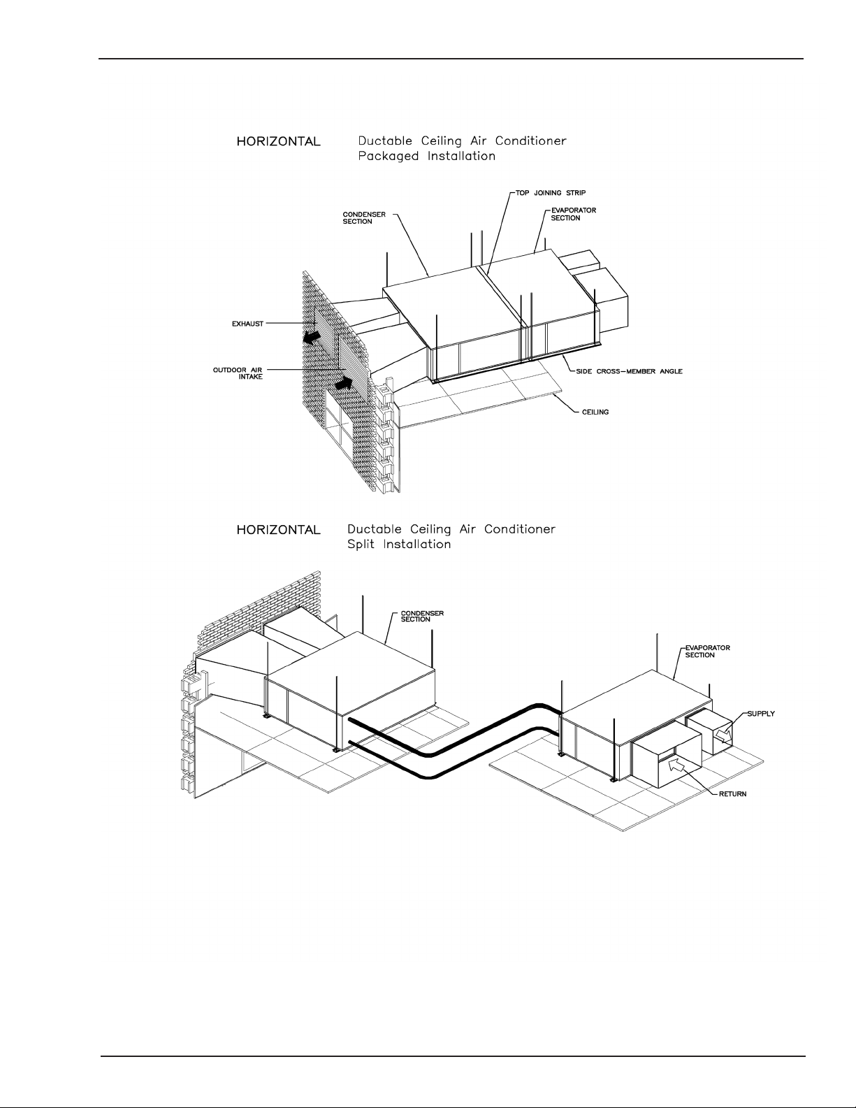
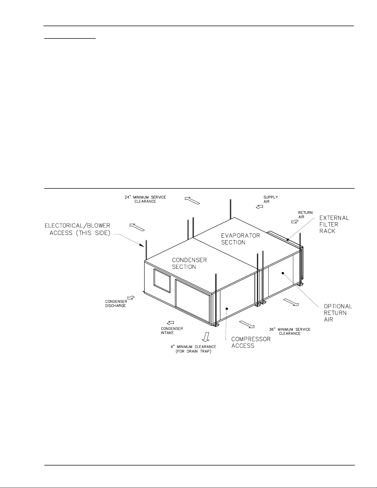
TYPICAL INSTALLATION DRAWING
FORM 145.32-IOM1 (908)
JOHNSON CONTROLS
5
FORM 145.32-IOM1 (908)
PRE-INSTALLATION INSPECTION OF EQUIPMENT
All units are factory tested to ensure safe operation
and quality assembly. Units are packaged and sealed
on shipping skids and shipped in rst class condition.
Torn and broken packaging, scratched or dented panels
should be reported to carrier immediately. An internal
inspection of each unit should be performed prior to
installation. Remove all access doors and check for
visual defects that can occur during transport. Any problems found internally should be reported to carrier and
manufacturer immediately. Refrigerant circuit should be
checked to ensure no leaks have occurred during shipment. Install gauge set on high and low pressure ports
to conrm pressure has been maintained and no leaks
have occurred during shipment. Repair any damage
prior to installation to ensure safe operation.
Record any unit damage on the Bill of
Lading and report to carrier and factory
immediately. Shipping and handling
damages are not warranty items.
RIGGING
Prior to mounting unit, check individual
unit weights (pages 7-8) and verify lifting
capacity of lifting equipment exceeds
weight of units by safe margins. Failure
to do so may result in unit damage, per-
sonal injury or even death.
INSTALLATION
Lock all electrical power supply switches in the off position before installing
the unit. Failure to disconnect power
supply may result in electrical shock or
even death.
Location - To ensure unit operates at maximum efciencies, choose a dry indoor area where the temperature
is controlled between 50 deg F and 115 deg F. Consideration of surrounding areas should be taken when
choosing a location to install the unit. Common vibration
and sound levels associated with commercial equipment
may be objectionable to people or equipment.
Failure to allow adequate space between
units may result in poor unit performance and possible unit failure.
Refer to typical installation diagram (Page #5).
Install thermostats, air supplies and returns so that each
unit will operate only on individual unit control. To assure
fast drainage of condensate run-off, unit can be slightly
pitched in the same direction as drain pan outlet.
To ensure safe installation of the unit when ceiling mount
application is specied, estimate the approximate center
of gravity of the unit. The conguration of internal com-
ponents for each unit is different and weight is unevenly
distributed.
Determine the actual center of gravity of
the unit by performing a test lift. Lifting
an unbalanced unit can cause personal
injury or even death.
6
JOHNSON CONTROLS
UNIT MOUNTING
FORM 145.32-IOM1 (908)
The 2 through 5 ton unit consist of an evaporator and
condenser module. These two modules are rigidly attached by a joining strip across the top of the two cabinet,
and two long side cross-member angles which bridge the
mounting channels on the bottom of the unit. These units
may be eld split to allow for passage through doors,
elevators, hallways, etc. Alternatively, the units may be
installed as a split system after separation.
Units may be either hung, or oor mounted. If unit is to
be hung, use all mounting points indicated - regardless
if unit is installed as a package or split system (See unit
dimension drawings). Use of 1/2in. dia hanger rods is
recommended. Ensure the attachment point of the rods
to the building structure is sufcient to support the unit
weight. In order to ensure efcient condensate drain-
age, the unit may be pitched towards the evaporator
end of the unit.
A minimum of 4-in. clearance is required under the unit to
allow for trapping of the evaporator condensate drain.
Floor mounted units should be secured on a solid, level
pad. The use of isolating vibro-pads at several points
under the bottom mounting channels is recommended.
Ensure that provision is made for clearance to install a
trap on the condensate drain outlet.
JOHNSON CONTROLS
7

FORM 145.32-IOM1 (908)
SEPARATION OF UNITS
The 2 through 5 ton units are provided with refrigerant
shut-off valves to allow the evaporator and condenser
sections to be eld split - without the necessity of reclaiming the entire unit refrigerant charge.
The evaporator and condenser sections may be separated by performing the following procedure:
1. Close all refrigerant shut-off valves, on both suction
and liquid lines. There are four valves in a single
compressor model, and a total of eight valves in the
dual compressor models. Valves are not a backseating design. Caps are wrench tight. Remove
caps and turn stem clockwise to seat in the closed
position.
2. Use the valve access ports to reclaim the refrigerant
trapped in the lines between the pairs of shut-off
valves.
3. Cut the refrigerant line sections between the pairs of
shut-off valves. It is recommended to make this out
where accessibility is greatest - in the condensing
section of the unit. This will allow best access for
reconnection, or attachment of an extended line
set in the case of a split system.
4. Remove the interconnecting wiring between the
evaporator and condenser electrical panel. Disconnect the wire terminations in the condenser
electrical panel, and pull the excess wire into the
evaporator panel.
5. Remove the threaded wire bushing connecting the
two electrical panels.
INTERCONNECTING REFRIGERANT TUBING
- SPLIT INSTALLATION
After the evaporator and condenser sections have been
mounted, the interconnecting refrigerant tubing can be
fabricated. Line sizing recommendations shown in the
accompanying table are suitable for most applications.
Consult sales ofce for applications outside the specied guidelines.
Route refrigerant tubing for minimum linear length, and
minimum number of bends and ttings. Use long radius
elbows for all 90-degree bends, except oil traps. Traps
should be constructed from short radius street elbows,
in order to keep the trap as small as possible. All brazing
should be done using a 2 to 8 psig dry nitrogen purge
owing through the pipe being brazed.
Once the brazing operation of refrigeration lines is com-
pleted, the eld-brazed connections must be checked for
leaks. Pressurize the system through the shut-off valve
ports with dry nitrogen to a minimum of 400 psig. Use
soap bubbles or alternate methods of leak-checking all
eld brazed joints. After completion of the leak check,
evacuate the interconnecting lines to hold a 350-micron
vacuum. If gauge pressure rises above 500 microns in
one minute, then evacuation is incomplete or the system
has a leak.
Additional refrigerant (R-410A) must be added to the
system due to the extended refrigerant lines. Calculate
the amount of additional refrigerant required as follows:
1. 5/16 in OD liquid line - add 0.40 oz per linear foot
2. 3/8 in OD liquid line - add 0.60 oz per linear foot
3. 1/2 in OD liquid line - add 1.20 oz per linear foot
4. 5/8 in OD liquid line - add 1.80 oz per linear foot
6. Remove the unit top-joining strip; take care to remove only those screws which attaches the joining
strip to the evaporator and condenser cabinets.
7. Remove the two side cross-member angles.
8. Carefully pull the evaporator section away from the
condenser section. Take care not to damage the
short lengths of refrigerant tubing extending into
the condenser section.
The separated evaporator and condenser modules may
now be individually moved to the proposed installation
site for re-assembly, or separately located for split applications.
8
JOHNSON CONTROLS
 Loading...