

Energy Systems & Design Easy Tune Stream Engine Owner's Manual

The Stream Engine®
Easy Tune® Generator
Owner’s Manual
Please Read Carefully
Made in North America
By
PO Box 4557
Sussex NB
Canada E4E 5L7
Phone +1 (506) 433-3151
Fax +1 (506) 433-6151
Email:
Website:
The Stream Engine and Easy Tune are a Trademark of Energy Systems & Design Ltd.
V1.0 7-2011
support@microhydropower.com
www.microhydropower.com

C
ongratulations on your purchase of a new Easy Tune Stream Engine! With a proper installation and a
little routine maintenance, your Stream Engine will provide you with years of trouble-free operation.
This manual will help you to install your machine as well as assist you in trouble-shooting and problem
solving. Of course, you may contact Energy Systems & Design Ltd. if you run into trouble.
May your RE adventures prove successful!
Table of Contents
Introduction..............................................................................................3
Site Evaluation.........................................................................................3
Head Measurement ..................................................................................3
Flow Measurement...................................................................................4
Stream Engine Output in Watts Table .....................................................5
Intake, Pipeline & Tailrace......................................................................6-7
Batteries, Inverters & Controllers............................................................7-8
Wiring and Load Center...........................................................................8-9
Design Example.......................................................................................9-10
Output Adjustment...................................................................................11
High Voltage ...........................................................................................12
Determining Nozzle Size.........................................................................12
Nozzle flow chart......................................................................................13
Disassembly and Bearing Replacement ..................................................13-15
Copper Wire Resistance Chart ................................................................15
Pipe Friction Head Loss Charts..............................................................16-17
Wiring......................................................................................................18-19
Installation Examples……………………………………………………20-21

INTRODUCTION
The Stream Engine uses a tunable permanent magnet type alternator called the Easy Tune ®. This
design eliminates the need for brushes and the maintenance that accompany them while increasing
efficiency. The Easy Tune’s output can be optimized by simply moving the upper part of the generator.
This manual describes The Easy Tune Stream Engine, which is manufactured by Energy Systems and
Design Ltd. The installer must have some knowledge of plumbing and electrical systems, as should the
end user of the system. These machines are small, but can generate very high voltages. Even 12-volt
machines can produce high voltages under certain conditions. Practice all due safety. Electricity cannot
be seen and can be lethal.
It is important to consult with local officials before conducting any watercourse alteration. ES&D
advises following all local laws and ordinances regarding watercourses.
Electricity is produced from the potential energy in water moving from a high point to a lower one. This
distance is called "head" and is measured in units of distance (feet, meters) or in units of pressure
(pounds per square inch, kilo-Pascals). "Flow" is measured in units of volume (gallons per minute gpm, or liters per second - l/s), and is the second portion of the power equation. The power available is
related to the head and the flow.
The Stream Engine is designed to operate over a wide range of heads and flows. This is achieved with
the use of a Turgo runner, or wheel. Nozzle diameters of 1/8 to 1 inch (3-25mm) are available, and up to
four nozzles can be used on one machine, to utilize heads as low as four feet and as high as hundreds.
SITE EVALUATION
Certain information must be determined concerning your site, in order to use its potential for maximum
output. Head and flow must first be determined. Other factors are: pipeline length, transmission distance,
and the system voltage. These factors determine how much power can be expected.
Power is generated at a constant rate by the Stream Engine and stored in batteries as direct current (DC).
Power is supplied, as needed, by the batteries, which store energy during periods of low consumption for
use in periods where consumption exceeds the generation rate. Appliances can be used that operate
directly from batteries, or 120 volt alternating current (AC) power can be supplied through an inverter,
converting DC to AC power.
Sites may vary, so carefully consider flow and head when choosing yours. Remember, maximum head
can be achieved by placing the Stream Engine at as low an elevation as possible, but going too low may
cause the machine to become submerged (or washed away!).
HEAD MEASUREMENT
Head may be measured using various techniques. A garden hose or length of pipe can be submerged
with one end upstream and the other end downstream. Anchor the upstream end with rocks or have an
assistant hold it; water should flow out the low end, especially if the pipeline is pre-filled. Once water is
flowing, raise the downstream end until it stops. Do this slowly since the water tends to oscillate. When
the flow has stabilized, measure the distance down to the level of water in the stream with a tape
measure. This will give a very accurate measurement of that stream section. Mark the spot and then
repeat the procedure until the entire distance is covered.
3
Another technique is to use a surveyor's transit. This method can also be approximated using a
carpenter's level along with a measuring stick or a "story pole." This technique is also done in a series of
steps to arrive at the overall head. A variation on this method is the use of altimeters. GPS equipment
could also be used to measure elevation.
FLOW MEASUREMENT
The easiest method to measure small flows is to channel the water into a pipe using a temporary dam
and to fill a container of known volume. Measuring the time to fill the container enables you to calculate
the flow rate.
4
WEIR MEASUREMENT TABLE
Table shows water flow in gallons/minute (gpm) that will flow over a weir one inch wide and from
1/8 to 10-7/8 inches deep.
Inches
0 0.0 0.1 0.4 0.7 1.0 1.4 1.9 2.4
1 3.0 3.5 4.1 4.8 5.5 6.1 6.9 7.6
2 8.5 9.2 10.1 10.9 11.8 12.7 13.6 14.6
3 15.5 16.5 17.5 18.6 19.5 20.6 21.7 22.8
4 23.9 25.1 26.2 27.4 28.5 29.7 31.0 32.2
5 33.4 34.7 36.0 37.3 38.5 39.9 41.2 42.6
6 43.9 45.3 46.8 48.2 49.5 51.0 52.4 53.9
7 55.4 56.8 58.3 59.9 61.4 63.0 64.6 66.0
8 67.7 69.3 70.8 72.5 74.1 75.8 77.4 79.1
9 80.8 82.4 84.2 85.9 87.6 89.3 91.0 92.8
10 94.5 96.3 98.1 99.9 101.7 103.6 105.4 107.3
Suppose depth of water above stake is 9 3/8 inches. Find 9 in the left-hand column and 3/8 in the
top column. The value where they intersect is 85.9 gpm. That's only for a 1-inch weir, however. You
multiply this value by the width of your weir in inches to obtain water flow.
1/8 1/4 3/8 1/2 5/8 3/4 7/8
Example of how to use weir table:

5
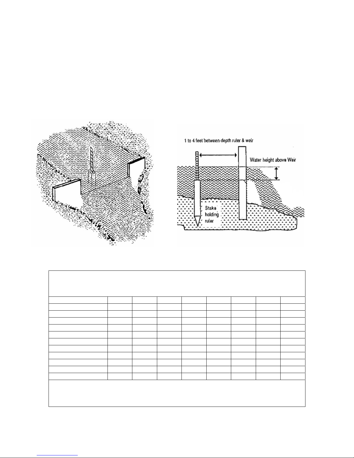
The weir method is more versatile and may prove useful for higher flows. This technique uses a
rectangular opening cut in a board or piece of sheet metal set into the brook like a dam. The water is
channeled into the weir and the depth is measured from the top of a stake that is level with the edge of
the weir and several feet upstream. Looking at the chart that follows will enable you to convert the width
and depth of flowing water into gallons per minute.
Measuring the flow at different times of the year helps you estimate maximum and minimum usable
flows. If the water source is seasonally limited, you may have to depend on some other source of power
during dry times (solar, wind). Keep in mind that a reasonable amount of water must be left in the
stream (Don't take it all, that water supports life forms).
When head and flow are determined, the expected power output can be determined from the following
chart. Keep in mind that chart values represent generated output and that actual power delivered to the
batteries will be reduced by transmission lines, power converters, and other equipment required by the
system. All systems should be carefully planned to maximize power output.
Stream Engine Output in Watts (Continuous)
Net Head
Liters/sec (Gallons/min)
Meters Feet
0.67
(10)
1.33
(20)
2.50
(40)
3 10 - 20 40 75 100 130 150
6 20 15 40 80 150 200 250 350
15 49 45 100 200 375 500 650 800
30 98 80 200 400 750 1000 * *
60 197 150 400 800 1500 * * *
90 295 200 550 1200 * * * *
120 394 300 700 1500 * * * *
150 492 400 850 1900 * * * *
* In these higher output situations, it may be worthwhile to utilize more than one Stream Engine.
Flow Rate
5.00
(75)
6.67
(100)
7.50
(112)
9.50
(150)

6
INTAKE, PIPELINE, AND TAILRACE
Most hydro systems require a pipeline. Even systems operating directly from a dam require at least a
short plumbing run. It is important to use the correct type and size of pipe to minimize restrictions in the
flow to the nozzle(s). When possible, pipelines should be buried; this stabilizes the line and prevents
animals from chewing it.
At the inlet of the pipe, a filter should be installed. A screened box can be used with the pipe entering
one side, or add a section of pipe drilled full of holes wrapped with screen or small holes and used
without screen. Make sure that the filter openings are smaller than the smallest nozzle used.
Note that particles over about ¼” or 6mm in size may lodge in the runner.
The intake must be above the streambed so as not to suck in silt and should be deep enough so as not to
suck in air. The intake structure should be placed to one side of the main flow of the stream so that the
force of the flowing water and its debris bypasses it. Routinely clean the intake of any leaves or other
debris.
If the whole pipeline doesn't run continuously downhill, at least the first section should, so the water can
begin flowing. A bypass valve may be necessary. This should be installed at a low point in the pipe.
For pipelines running over dams, or in conditions that create a siphon, the downstream side may be
filled by hand. Once filled, the stop valve at the turbine can be opened to start the flow. If full pressure is
not developed, or air builds up in the line, a hand-powered vacuum pump can be used to remove air
trapped at the high point.
At the turbine end of the pipeline a bypass valve may be necessary to allow water to run through the
pipe without affecting the turbine, purging the line of air or increasing flow to prevent freezing.
A stop valve should be installed upstream of the nozzle. A pressure gauge should be installed upstream
of the stop valve so both the static head (no water flowing) and the dynamic head (water flowing) can be
read.
The stop valve on a pipeline should always be closed slowly to prevent water hammer (the column of
water in the pipe coming to an abrupt stop). This can easily destroy your pipeline and for this reason,
you may wish to install a pressure relief valve just upstream of the stop valve. This can also occur if
debris clogs the nozzle. In a single nozzle machine a nozzle that becomes clogged suddenly may create a
water hammer.
Nozzles can be installed or changed by removing the nozzle. The nozzle is removed by unscrewing its
four nuts using a 7/16” (11 mm) wrench. The use of flexible pipe makes it easier to remove the
plumbing from the nozzles.

11” 28cm
BOLT HOLES – ¼” dia 6mm
7
11”
28cm
9 1/2” Square Base Opening
24cm
12” 30.5cm
OUTSIDE DIMENSION
The turbine housing can be mounted on two boards to suspend it above the stream. It is recommended to
have the Stream Engine in a small enclosure or under some cover to keep it dry and provide a place for
auxiliary equipment. Mounting the machine in concrete is also possible (you may wish to try a
temporary wood mounting first). The opening under the housing to catch the water should be at least the
size of the turbine housing opening, and preferably a little larger. Make certain the tailrace (exit channel)
provides enough flow for the exiting water. The diameter of the bolt holes is ¼” (6mm).
In cold climates, it may be necessary to build a "trap" into the exit. This prevents outside air from
entering the housing and causing freeze-ups.
BATTERIES, INVERTERS & CONTROLLERS
System Voltage
A small system with a short transmission distance can be designed to operate at 12 volts. Larger systems
can also be 12 volts, but if higher power is desired or the transmission distance is long, then a system of
24 volts or higher may be preferable. This is especially true if all loads are inverter-powered. In a 12volt system operating at a low power level, it may be advantageous to operate all loads directly from
batteries. Many 12-volt appliances and small inverters are available. In 24-volt systems, it may also be
preferable to operate the loads directly (although not as many appliances are available).
 Loading...