

Energy Star RLNL 13 series, RLNL 14 series Installation Instructions Manual
INSTALLATION INSTRUCTIONS
ISO 9001:2008
Package Air Conditioners Featuring
Industry Standard R-410A Refrigerant
RLNL 13 SEER (3-5 TONS) SERIES
RLPL 14 SEER (3-5 TONS) SERIES
(14 SEER ONLY)
[ ] INDICATES METRIC CONVERSION
ISO 9001:2000
92-23577-76-05
SUPERSEDES 92-23577-76-04

I. TABLE OF CONTENTS
I. Table of Contents...........................................................................2
II. Introduction.....................................................................................3
III. Checking Product Received...........................................................3
IV. Specifications.................................................................................3
V. Equipment Protection.....................................................................4
Vi. Installation......................................................................................7
A. General .....................................................................................7
1. Pre-Installation Check Points................................................7
2. Location ................................................................................7
B. Outside Slab Installation ...........................................................7
C. Clearances................................................................................8
D. Rooftop Installation...................................................................8
VII. Ductwork ........................................................................................9
VIII. Filters............................................................................................10
IX. Conversion Procedure..................................................................10
X. Condensate Drain ........................................................................10
XI. Electrical Wiring............................................................................11
A. Power Wiring...........................................................................11
B. Special Instructions for Power
Wiring with Aluminum Conductors..........................................11
C. Control Wiring.........................................................................12
D. Internal Wiring.........................................................................13
E. Grounding ...............................................................................13
F. Thermostat..............................................................................13
XII. Indoor Air Flow Data.....................................................................14
XIII. Crankcase Heat............................................................................14
XIV. Pre-Start Check............................................................................14
XV. Startup..........................................................................................14
XVI. Operation......................................................................................15
XVII. Auxiliary Heat...............................................................................15
XVIII.General Data...........................................................................16-41
XIX. Miscellaneous...............................................................................42
Electrical & Physical Data.......................................................42-47
Airflow Performance................................................................48-53
Heater Kit Characteristics .......................................................54-67
Wiring Diagrams......................................................................68-73
Charge Charts.........................................................................74-78
Troubleshooting............................................................................79
2
Recognize this symbol as an indi-
!
cation of Important Safety
Information!
WARNING
!
PROPOSITION 65: THIS APPLIANCE CONTAINS FIBERGLASS
INSULATION. RESPIRABLE
PARTICLES OF FIBERGLASS
ARE KNOWN TO THE STATE
OF CALIFORNIA TO CAUSE
CANCER..
WARNING
!
THE MANUFACTURER’S WARRANTY DOES NOT COVER ANY
DAMAGE OR DEFECT TO THE
AIR CONDITIONER CAUSED BY
THE ATTACHMENT OR USE OF
ANY COMPONENTS, ACCESSORIES OR DEVICES (OTHER
THAN THOSE AUTHORIZED BY
THE MANUFACTURER) INTO,
ONTO OR IN CONJUNCTION
WITH THE AIR CONDITIONER.
YOU SHOULD BE AWARE THAT
THE USE OF UNAUTHORIZED
COMPONENTS, ACCESSORIES
OR DEVICES MAY ADVERSELY
AFFECT THE OPERATION OF
THE AIR CONDITIONER AND
MAY ALSO ENDANGER LIFE
AND PROPERTY. THE MANUFACTURER DISCLAIMS ANY
RESPONSIBILITY FOR SUCH
LOSS OR INJURY RESULTING
FROM THE USE OF SUCH
UNAUTHORIZED COMPONENTS, ACCESSORIES OR
DEVICES.
II. INTRODUCTION
This booklet contains the installation and operating instructions for your package air conditioner. There are a few precautions that should be taken to derive maximum satisfaction from it. Improper installation can result in unsatisfactory operation or dangerous conditions.
Read this booklet and any instructions packaged with separate equipment required to
make up the system prior to installation. Give this booklet to the owner and explain its
provisions. The owner should retain this booklet for future reference.
III. CHECKING PRODUCT RECEIVED
Upon receiving the unit, inspect it for any damage from shipment. Claims for damage,
either shipping or concealed, should be filed immediately with the shipping company.
Check the unit model number, electrical characteristics, and accessories to determine if
they are correct.
IV. SPECIFICATIONS
A. GENERAL
The Packaged Air Conditioner is available without heat or with 6, 10, 12, 15, 20 or 24
kW electric heat. Cooling capacities of 3, 3
able. Units are convertible from end supply and return to bottom supply and return by
relocation of supply and return air access panels. See cover installation detail.
The units are weatherized for mounting outside of the building.
The information on the rating plate is in compliance with the FTC and DOE rating for sin-
gle phase units. The following information is for three phase units which are not covered
under the DOE certification program.
1. The efficiency rating of this unit is a product thermal efficiency rating determined
under continuous operating conditions independent of any installed system.
B. MAJOR COMPONENTS
The unit includes a hermetically-sealed refrigerating system (consisting of a compressor,
condenser coil, evaporator coil with thermal expansion valve), a circulation air blower, a
condenser fan, and all necessary internal electrical wiring. The cooling system of these
units is factory-evacuated, charged and performance tested. Refrigerant amount and
type are indicated on rating plate.
C. R-410A REFRIGERANT
All units are factory charged with R-410A refrigerant.
1. Specification of R-410A:
Application: R-410A is not a drop-in replacement for R-22; equipment designs must
accommodate its higher pressures. It cannot be retrofitted into R-22 units.
Pressure: The pressure of R-410A is approximately 60% (1.6 times) greater than
R-22. Recovery and recycle equipment, pumps, hoses and the like need to have design
pressure ratings appropriate for R-410A. Manifold sets need to range up to 800 psig
high-side and 250 psig low-side with a 550 psig low-side retard. Hoses need to have a
service pressure rating of 800 psig. Recovery cylinders need to have a 400 psig service
pressure rating. DOT 4BA400 or DOT BW400.
Combustibility: At pressures above 1 atmosphere, mixture of R-410A and air can
become combustible. R-410A and air should never be mixed in tanks or supply
lines, or be allowed to accumulate in storage tanks. Leak checking should never
be done with a mixture of R-410A and air. Leak checking can be performed safely
with nitrogen or a mixture of R-410A and nitrogen.
1
⁄2 , 4 and 5 nominal tons of cooling are avail-
2. Quick Reference Guide For R-410A
• R-410A refrigerant operates at approximately 60% higher pressure (1.6 times) than R-
22. Ensure that servicing equipment is designed to operate with R-410A.
• R-410A refrigerant cylinders are pink.
• R-410A, as with other HFC’s is only compatible with POE oils.
• Vacuum pumps will not remove moisture from POE oil.
3
• R-410A systems are to be charged with liquid refrigerants. Prior to March 1999, R410A refrigerant cylinders had a dip tube. These cylinders should be kept upright for
equipment charging. Post March 1999 cylinders do not have a dip tube and should
be inverted to ensure liquid charging of the equipment.
• Do not install a suction line filter drier in the liquid line.
• A liquid line filter drier is standard on every unit.
• Desiccant (drying agent) must be compatible for POE oils and R-410A.
3. Evaporator Coil / TXV
The thermostatic expansion valve is specifically designed to operate with R-410A. DO
NOT use an R-22 TXV. The existing evaporator must be replaced with the factory
specified TXV evaporator specifically designed for R-410A.
4. Tools Required For Installing & Servicing R-410A Models
Manifold Sets:
-Up to 800 PSIG High side
-Up to 250 PSIG Low Side
-550 PSIG Low Side Retard
Manifold Hoses:
-Service Pressure Rating of 800 PSIG
Recovery Cylinders:
-400 PSIG Pressure Rating
-Dept. of Transportation 4BA400 or BW400
!
CAUTION
R-410A systems operate at higher pressures than R-22 systems. Do not use
R-22 service equipment or components on R-410A equipment.
V. EQUIPMENT PROTECTION FROM THE
ENVIRONMENT
The metal parts of this unit may be subject to rust or deterioration in adverse environmental conditions. This oxidation could shorten the equipment’s useful life. Salt spray,
fog or mist in seacoast areas, sulphur or chlorine from lawn watering systems, and various chemical contaminants from industries such as paper mills and petroleum refineries
are especially corrosive.
If the unit is to be installed in an area where contaminants are likely to be a problem, special attention should be given to the equipment location and exposure.
1. Avoid having lawn sprinkler heads spray direction on the unit cabinet.
2. In coastal areas, locate the unit on the side of the building away from the waterfront.
3. Shielding provided by a fence or shrubs may give some protection.
Regular maintenance will reduce the buildup of contaminents and help to protect
the unit’s finish.
WARNING
!
DISCONNECT ALL POWER TO THE UNIT BEFORE STARTING MAINTENANCE. FAILURE TO DO SO CAN RESULT IN SEVERE ELECTRICAL
SHOCK OR DEATH.
1. Frequent washing of the cabinet, fan blade and coil with fresh water will remove
most of the salt or other contaminants that build up on the unit.
2. Regular cleaning and waxing of the cabinet with a good automobile polish will provide some protection.
3. A good liquid cleaner may be used several times a year to remove matter that will
not wash off with water.
Several different types of protective coatings are offered in some areas. These coatings
may provide some benefit, but the effectiveness of such coating materials cannot be verified by the equipment manufacturer.
The best protection is frequent cleaning, maintenance and minimal exposure to
contaminants.
4
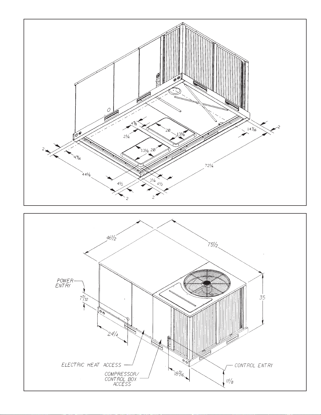
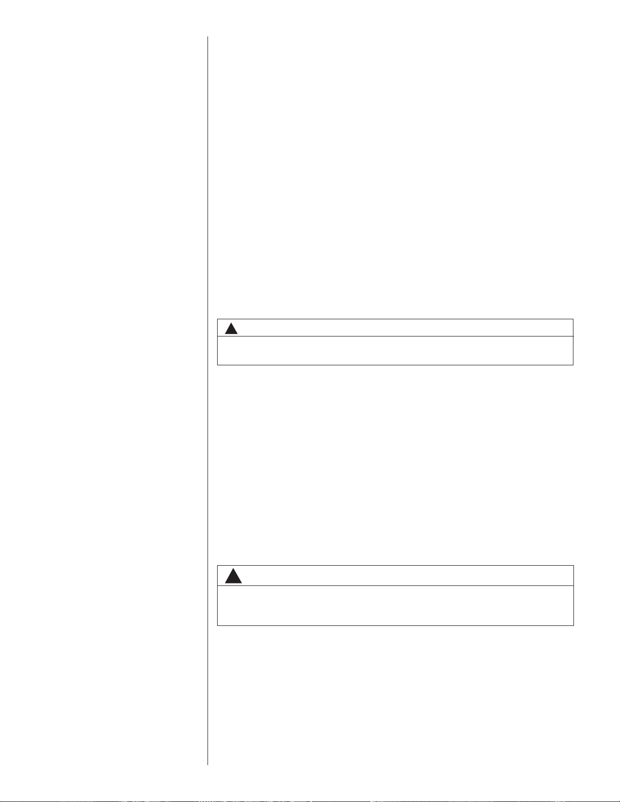
FIGURE 1
UNIT DIMENSIONS
FIGURE 2
UNIT DIMENSIONS
ILL 1316
ILL1305
5
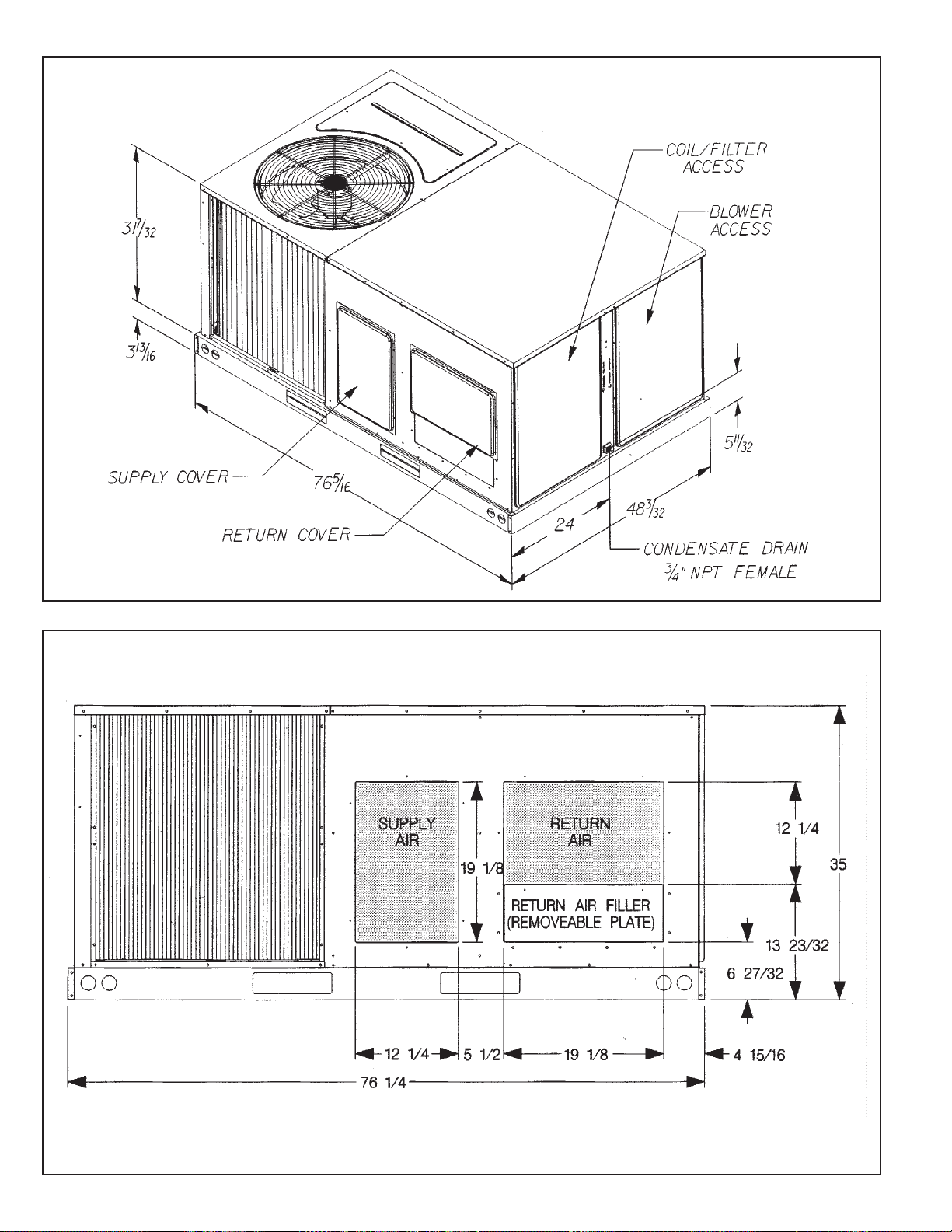
FIGURE 3
UNIT DIMENSIONS
FIGURE 4
UNIT DIMENSIONS
ILL 1304
ILL 1288
6
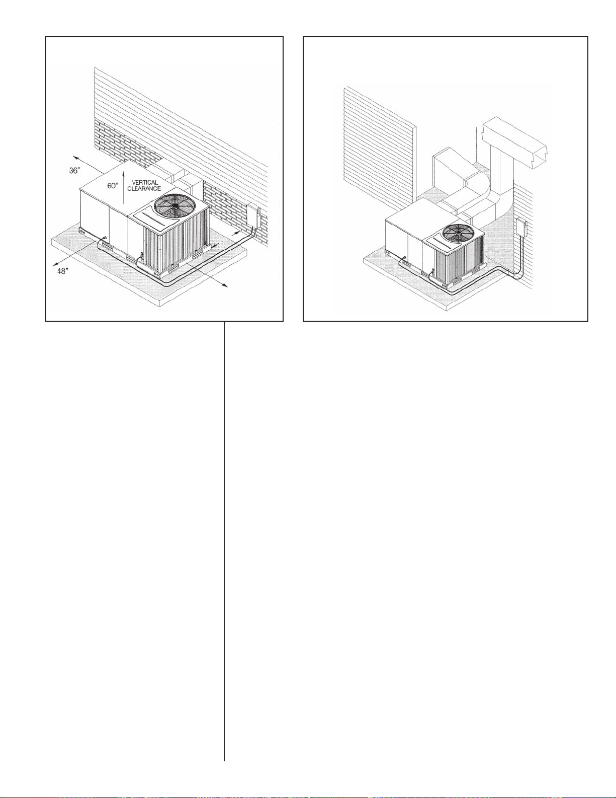
FIGURE 5
PACKAGE AIR CONDITIONER – OUTSIDE SLAB INSTALLATION,
BASEMENT OR CRAWL SPACE DISTRIBUTION SYSTEM
*
12”
FIGURE 6
PACKAGE AIR CONDITIONER – OUTSIDE SLAB INSTALLATION, CLOSET
DISTRIBUTION SYSTEM. SLAB FLOOR CONSTRUCTION
*
Allow 57" for
economizer on duct side.
18”
ILL I308
VI. INSTALLATION
A. GENERAL
1. PRE-INSTALLATION CHECK-POINTS
Before attempting any installation, the following points should be carefully consid-
ered:
a. Structural strength of supporting members.
(rooftop installation)
b. Clearances and provision for servicing.
c. Power supply and wiring.
d. Air duct connections.
e. Drain facilities and connections.
f. Location for minimum noise.
2. LOCATION
These units are designed for outdoor installations. They can be mounted on a
slab or rooftop. They are not to be installed within any part of a structure such as
an attic, crawl space, closet, or any other place where condenser air flow is
restricted or other than outdoor ambient conditions prevail. Since the application
of the units is of the outdoor type, it is important to consult your local code authorities at the time the first installation is made.
ILL I309
B. OUTSIDE SLAB INSTALLATION
(Typical outdoor slab installations are shown in Figures 5 and 6.)
1. Select a location where external water drainage cannot collect around the unit.
2. Provide a level concrete slab extending 3" beyond all four sides of the unit. The
slab should be sufficient above grade to prevent ground water from entering the
unit. IMPORTANT: To prevent transmission of noise or vibration, slab should not
be connected to building structure.
3. The location of the unit should be such as to provide proper access for inspection
and servicing.
4. Locate unit where operating sounds will not disturb owner or neighbors.
5. Locate unit so roof runoff water does not pour directly on the unit. Provide gutter
or other shielding at roof level. Do not locate unit in an area where excessive
snow drifting may occur or accumulate.
6. Remove compressor shipping supports (if so equipped) after installation.
7
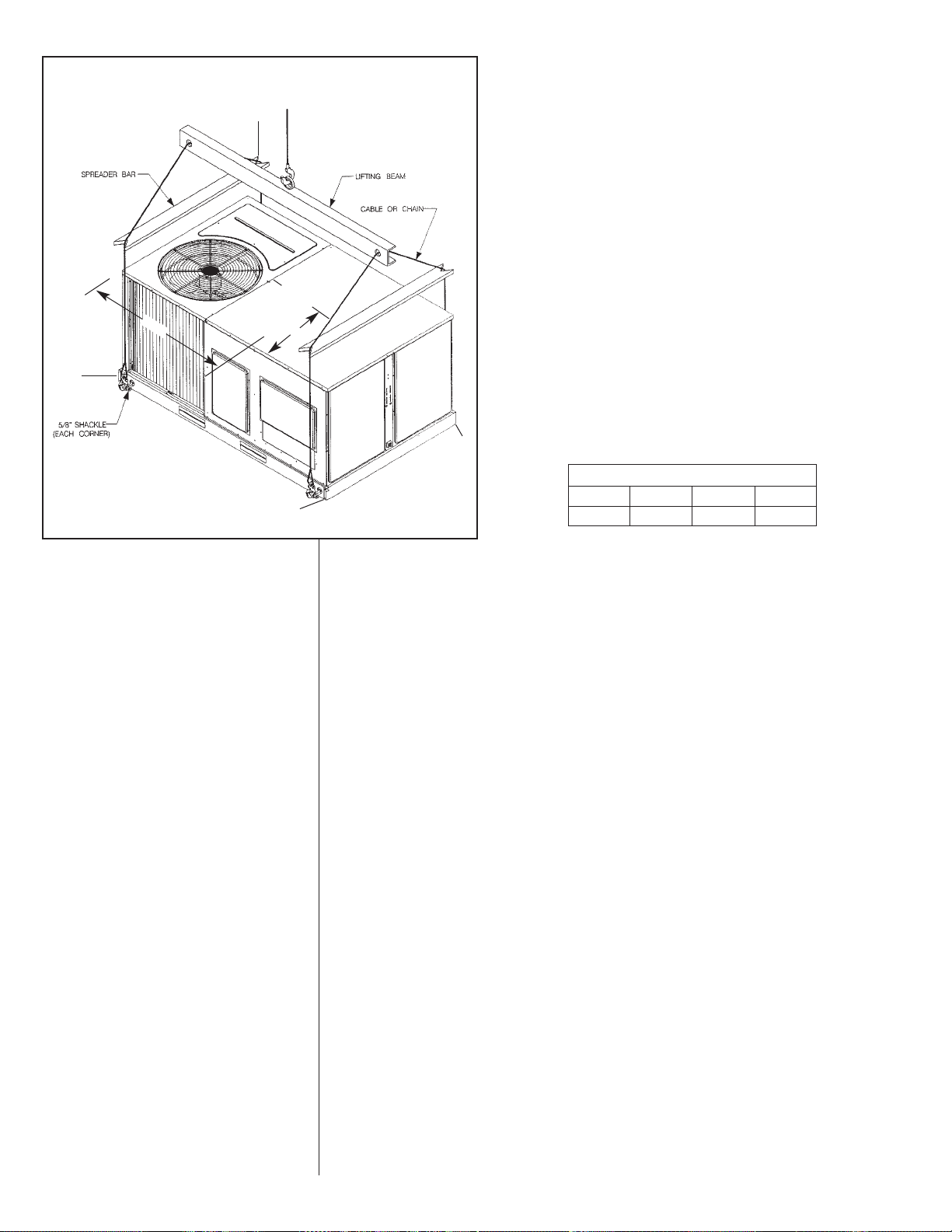
FIGURE 7
PACKAGE AIR CONDITIONER – RIGGING FOR LIFTING
B
CENTER
GRAVITY
OF
38-1/4
A
25-3/4
C
ILL I296
D
CORNER WEIGHTS BY PERCENTAGE
AB CD
23% 27% 23% 27%
C. CLEARANCES
The following minimum clearances must be observed for proper unit performance
and serviceability.
1. Provide 48" minimum clearance at the front of the unit. Provide 36" minimum
clearance at the left and right side of the unit for service access.
2. Provide 60" minimum clearance between top of unit and maximum 3 foot overhang.
3. Unit is design certified for application on combustible flooring with 0" minimum
clearance.
4. See Figure 5 for illustration of minimum installation-service clearances.
D. ROOFTOP INSTALLATION
1. Before locating the unit on the roof, make sure that the strength of the roof and
beams is adequate at that point to support the weight involved. (See specification
sheet for weight of unit.) This is very important and user’s responsibility.
2. For rigging and roofcurb details, see Figures 7 and 8. Use field-furnished spreaders.
3. For roofcurb assembly, see Roofcurb Installation Instructions.
4. If the roofcurb is not used, provisions for disposing of condensate water runoff
must be provided.
5. The unit should be placed on a solid and level roofcurb or platform of adequate
strength. See Figure 9.
6. The location of the unit on the roof should be such as to provide proper access for
inspection and servicing.
7. Remove compressor shipping supports (if so equipped) after installation.
IMPORTANT: If unit will not be put into service immediately, cover supply and return
openings to prevent excessive condensation.
8
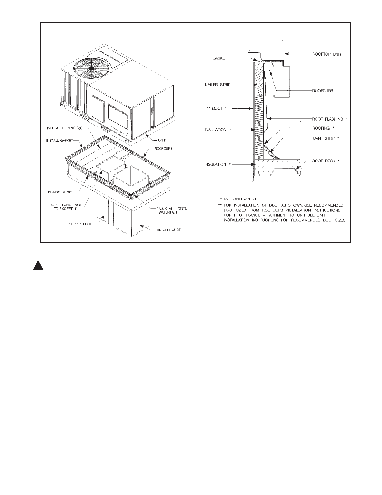
FIGURE 8
PACKAGE AIR CONDITIONER – ROOFCURB INSTALLATION
ILL I301
WARNING
!
DO NOT, UNDER ANY CIRCUMSTANCES, CONNECT RETURN
DUCTWORK TO ANY OTHER HEAT
PRODUCING DEVICE SUCH AS A
FIREPLACE INSERT, STOVE, ETC.
UNAUTHORIZED USE OF SUCH
DEVICES MAY RESULT IN FIRE,
CARBON MONOXIDE POISONING,
EXPLOSION, PROPERTY DAMAGE,
SEVERE PERSONAL INJURY OR
DEATH.
ILL I300
VII.DUCTWORK
Ductwork should be fabricated by the installing contractor in accordance with local codes
and NFPA90A. Industry manuals may be used as a guide when sizing and designing the
duct system - contact Air Conditioning Contractors of America, 2800 Shirlington Road,
Suite 300, Arlington, VA 22206, http://www.acca.org.
The unit should be placed as close to the space to be air conditioned as possible allowing clearance dimensions as indicated. Ducts should be run as directly as possible to
supply and return outlets. Use of non-flammable waterproof flexible connectors on both
supply and return connections at the unit to reduce noise transmission is recommended.
It is preferable to install the unit on the roof of the structure if the registers or diffusers
are located on the wall or in the ceiling. A slab installation could be considered when the
registers are low on a wall or in the floor.
On ductwork exposed to outside air conditions of temperature and humidity, use a minimum of 2" of insulation and a vapor barrier. Distribution system in attic, furred space or
crawl space should be insulated with at least 2" of insulation with vapor barrier. One-half
to 1" thickness of insulation is usually sufficient for ductwork inside the air conditioned
space.
Balancing dampers should be provided for each branch duct in the supply system.
Ductwork should be properly supported from the structure.
When installing ductwork, consider the following items:
1. Noncombustible flexible connectors should be used between ductwork and unit to
reduce noise and vibration transmission into the ductwork.
2. When auxiliary heaters are installed, use noncombustible flexible connectors and
clearance to combustible material of 0" for the first 3 feet of discharge duct.
Clearance to unit top and side is 0".
9
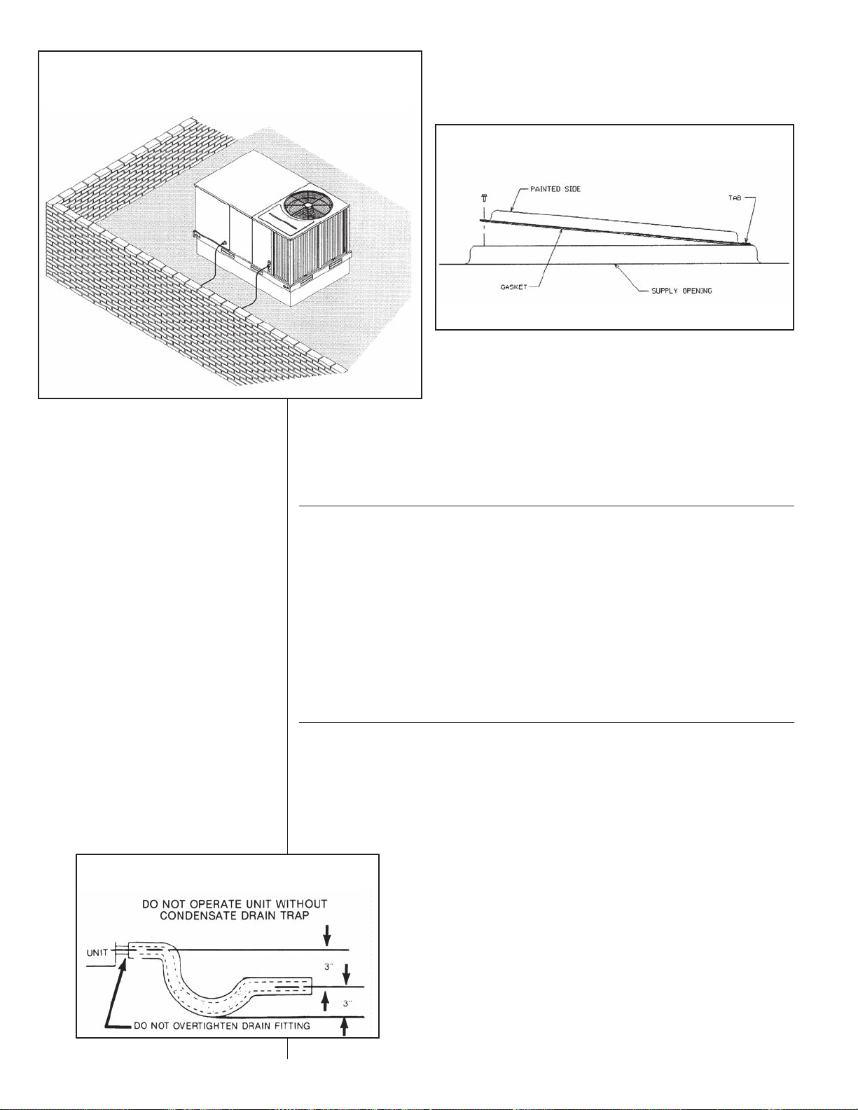
FIGURE 9
PACKAGE AIR CONDITIONER – FLAT ROOFTOP INSTALLATION, ATTIC OR
DROP CEILING DISTRIBUTION SYSTEM. MOUNTED ON ROOFCURB. CURB
MUST BE LEVEL
ILL I310
VIII.FILTERS
This unit is provided with 2 - 25" x 16" x 1" disposable filters. When replacing filters,
ensure they are inserted fully to the back to prevent bypass.
FIGURE 10
COVER GASKET DETAIL
ILL I631
FIGURE 11
CONDENSATE DRAIN
IX. CONVERSION PROCEDURE
DOWNFLOW TO HORIZONTAL
1. Remove the screws and covers from the outside of the supply and return sections.
2. Install the covers in the bottom supply and return openings with the painted side up.
See Figure 10. Use the existing gasket to seal the covers.
3. Secure the supply cover to the base of the unit with 1 screw, engaging prepunched
tab in unit base.
4. Secure the return cover to the base of the unit with screws, engaging prepunched
holes in the unit base.
X. CONDENSATE DRAIN
The condensate drain connection of the evaporator is 3/4" nominal female pipe thread.
IMPORTANT: Install a condensate trap to ensure proper condensate drainage. See
Figure 11.
10
XI. ELECTRICAL WIRING
Field wiring must comply with the National Electrical Code* and local ordinances that
may apply.
*C.E.C. in Canada
A. POWER WIRING
1. It is important that proper electrical power is available at the unit. Voltage should
not vary more than 10% from that stamped on the unit rating plate. On three
phase units, phases must be balanced within 3%.
2. Install a branch circuit disconnect within sight of the unit and of adequate size to
handle the starting current. Reference Figure 12 for proper location.
3. For branch circuit wiring (main power supply to unit disconnect), the minimum
wire size can be determined from Table A using the circuit ampacity found on the
unit nameplate.
TABLE A
4
3
12
20
2
4
3
4
4
6
6
8
8
10
25
300
4
250
Supply
Wire
Length
Feet
NOTE:
1. Wire size based on 60ºC type copper conductors below 100 ampacity. 2. Wire size based on 75ºC type copper conductors for 100 ampacity and above.
200
150
100
50
6
8
10
14
15
COPPER WIRE SIZE — AWG (1% VOLTAGE DROP)
1
1/0
1/0
2/0
2/0
3/0
3/0
3/0
4/0
4/0
10
30
2
3
2
1
1
1/0
1/0
2/0
2/0
2/0
4
3
2
2
1
1
1/0
4
4
4
3
45
3
4
4
6
6
50
55
6
6
6
8
8
35
40
1/0
2
2
4
3
6
4
60
65
3/0
1/0
2/0
1
1
1/0
3
2
4
4
70
75
3/0
2/0
1/0
2
2
3
3
80
Circuit Ampacity
4/0
3/0
2/0
1/0
85
250
250
4/0
4/0
4/0
3/0
3/0
1/0
2/0
1
1
2
3
90
95
250
4/0
4/0
3/0
3/0
2/0
2/0
1
1
2
100
1
2
105
2
250
4/0
3/0
2/0
1/0
2
110
300
250
4/0
2/0
1/0
1
115
300
250
4/0
3/0
1/0
1
120
300
250
4/0
3/0
1/0
1
125
300
250
4/0
3/0
1/0
1
130
300
250
4/0
3/0
1/0
1/0
135
350
350
300
4/0
1/0
1/0
140
350
350
300
4/0
2/0
1/0
145
350
350
300
4/0
2/0
1/0
150
4. This unit incorporates single point electrical connection for unit and electric heat
accessory.
5. Power wiring must be run in grounded rain-tight conduit. Connect the power field
wiring as follows:
a. NO ELECTRIC HEAT - Connect the field wires directly to the contactor pigtail
in the electric heat access area. Connect ground wire to ground lug.
b. WITH ELECTRIC HEAT - Connect the field wires to the terminal block on the
electric heater kit in the electric heat access area. Connect the ground wire to
the ground lug on the heater kit.
NOTE: For field installation of a heater kit, follow the instructions provided with the
heater kit.
6. The pigtail wires in the electric heat access area are factory wired to the contactor
in the control box.
7. DO NOT connect aluminum field wires to electric heat kit power input terminals.
350
350
300
4/0
2/0
2/0
155
B. SPECIAL INSTRUCTIONS FOR POWER WIRING WITH ALUMINUM
CONDUCTORS
1. Select the equivalent aluminum wire size from the tabulation below:
TABLE B. WIRE SIZES
AWG Copper AWG Aluminum Connector Type and Size
Wire Size Wire Size (or equivalent)
#12 #10 T&B Wire Nut PT2
#10 #8 T&B Wire Nut PT3
#8 #6 Ilsco Split Bolt AK-6
#6 #4 Ilsco Split Bolt AK-4
#4 #2 Ilsco Split Bolt AK-2
#3 #1 Ilsco Split Bolt AK-1/0
#2 #0 Ilsco Split Bolt AK-1/0
#1 #00 Ilsco Split Bolt AK-2/0
#0 #000 Ilsco Split Bolt AK-4/0
2.
Attach a length (6" or more) of recommended size copper wire to the unit terminals L1 and L3 for single phase, L1, L2, L3 for three phase.
11
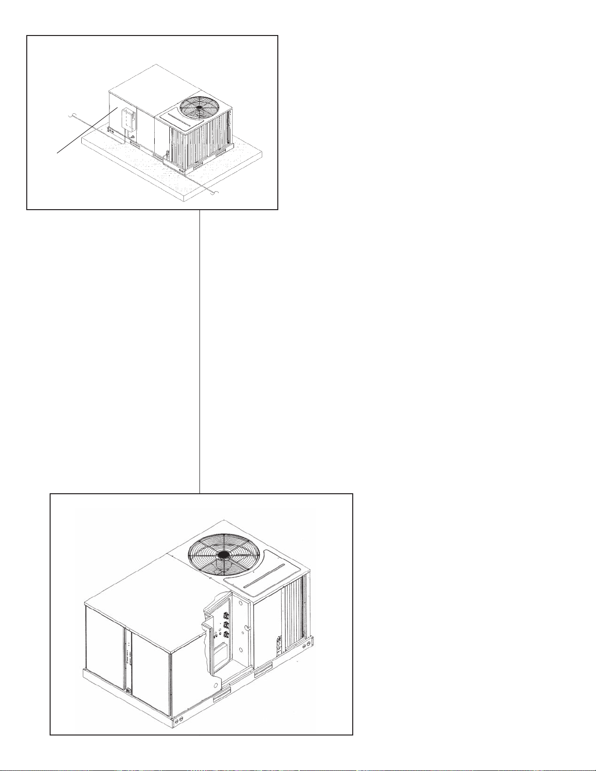
FIGURE 12
RECOMMENDED LOCATION OF BRANCH CIRCUIT DISCONNECT
TO POWER
BRANCH CIRCUIT DISCONNECT
TO CONTROL
3. Splice copper wire pigtails to aluminum wire with U.L. recognized connectors for
copper-aluminum splices. Follow these instructions very carefully to make a positive and lasting connection;
a. Strip insulation from aluminum conductor.
b. Coat the stripped end of the aluminum wire with the recommended inhibitor
c. Clean and recoat aluminum conductor with inhibitor.
d. Make the splice using the above listed wire nuts or split bolt connectors.
e. Coat the entire connection with inhibitor and wrap with electrical insulating
tape.
WARRANTY MAY NOT APPLY IF CONNECTIONS ARE NOT MADE PER INSTRUCTIONS
and wire brush aluminum surface through inhibitor. Inhibitors: Brundy, Pentex
“A”; Alcoa, No. 2EJC; T&B KPOR Shield.
FIGURE 13
HEATER KIT INSTALLATION
C. CONTROL WIRING (Class II)
1. Low voltage wiring should not be run in conduit with power wiring.
2. Control wiring is routed through the 7/8" hole adjacent to the compressor access
panel. See Figure 2. Use a minimum #18 AWG thermostat wire. For wire lengths
exceeding 50', use #16 AWG thermostat wire. The low voltage wires are connected to the unit pigtails which are supplied with the unit in the low voltage connection box located below the unit control box.
12
ILL I312
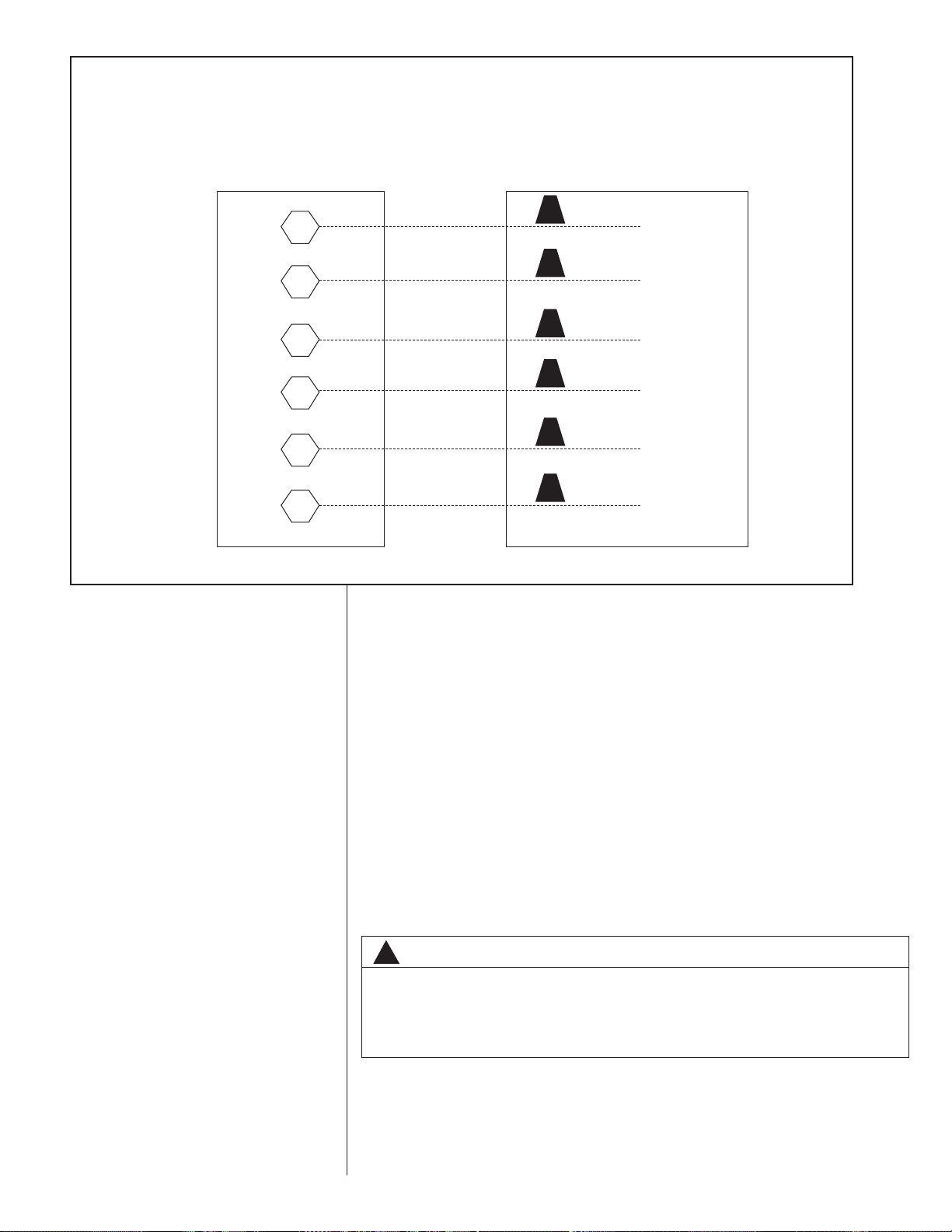
FIGURE 14
LOW VOLTAGE CONNECTIONS DIAGRAMS
STANDARD CONTROL WIRING
THERMOSTAT
SUB-BASE
R
W
G
Y
Y2
C
NOTE: Y2 IS ONLY USED WITH OPTIONAL ECONOMIZER.
UNIT CONTROLS
WIRE PIGTAILS
RED
BLACK
GRAY
YELLOW
ORANGE
BROWN
3. Figure 14 shows representative low voltage connection diagrams. Read your thermostat installation instructions for any special requirements for your specific thermostat.
NOTE — Units installed in Canada require that an outdoor thermostat (30,000
min. cycles of endurance) be installed and be wired with C.E.C. Class I wiring.
D. INTERNAL WIRING
IMPORTANT: Some single phase models are equipped with a single pole contactor.
Caution must be exercised when servicing as only one leg of the power supply is
broken with the contactor.
Some models are equipped with electronically commutated blower motors which are
constantly energized unless the main unit disconnect is in the off position.
1. A diagram of the internal wiring of this unit is located on the inside of the compressor access panel. If any of the original wire as supplied with the appliance
must be replaced, the wire gauge and insulation must be the same as original
wiring.
E. GROUNDING
WARNING
!
THE UNIT MUST BE PERMANENTLY GROUNDED. A GROUNDING LUG IS
PROVIDED IN THE ELECTRIC HEAT KIT ACCESS AREA FOR A GROUND
WIRE. FAILURE TO GROUND THIS UNIT CAN RESULT IN FIRE OR ELECTRICAL SHOCK CAUSING PROPERTY DAMAGE, SEVERE PERSONAL INJURY OR
DEATH.
F. THERMOSTAT
The thermostat should be mounted on an inside wall about five feet above the floor
in a location where it will not be affected by unconditioned air, sun, or drafts from
open doors or other sources. READ installation instructions in thermostat package
CAREFULLY because each has some different wiring requirements.
13

XII. INDOOR AIR FLOW DATA
Direct-drive blower models are shipped factory wired for the proper speed at a typical
external static. See Blower Performance Data. Belt-drive blower models have motor
sheaves set for proper CFM at a typical external static.
XIII.CRANKCASE HEAT (OPTIONAL)
Crankcase heat is not required on scroll type compressors, but may be necessary for
difficult starting situations.
XIV.PRE-START CHECK
1. Is unit properly located and slightly slanted toward indoor condensate drain?
2. Is ductwork insulated, weatherproofed, with proper spacing to combustible materials?
3. Is air free to travel to and from outdoor coil? (See Figure 5.)
4. Is the wiring correct, tight, and according to unit wiring diagram?
5. Is unit grounded?
6. Are field supplied air filters in place and clean?
7. Do the outdoor fan and indoor blower turn freely without rubbing, and are they tight
on the motor shafts?
8. Are the compressor shipping supports removed (if so equipped)?
XV. STARTUP
1. Turn thermostat to “OFF,” turn “on” power supply at disconnect switch.
2. Turn temperature setting as high as it will go.
3. Turn fan switch to “ON.”
4. Indoor blower should run. Be sure it is running in the right direction.
5. Turn fan switch to “AUTO.” Turn system switch to “COOL” and turn temperature setting below room temperature. Unit should run in cooling mode.
6. Is outdoor fan operating correctly in the right direction?
7. Is compressor running correctly.
8. Check the refrigerant charge using the instructions located on compressor access
panel. Replace service port caps. Service port cores are for system access only and
will leak if not tightly capped.
9. Turn thermostat system switch to proper mode “HEAT” or “COOl” and set thermostat
to proper temperature setting. Record the following after the unit has run some time.
A. Operating Mode _______________________________
B. Discharge Pressure (High)_PSIG
C.Vapor Pressure at Compressor (Low) __________PSIG
D.VaporLine Temperature at Compressor ___________°F.
E. Indoor Dry Bulb______________________________°F.
F. Indoor Wet Bulb _____________________________°F.
G.Outdoor Dry Bulb ____________________________°F.
H.Outdoor Wet Bulb____________________________°F.
I. Voltage at Contactor ________________________Volts
J. Current at Contactor _______________________Amps
K. Model Number_________________________________
L. Serial Number _________________________________
M.Location______________________________________
N.Owner _______________________________________
O.Date_________________________________________
10. Adjust discharge air grilles and balance system.
11. Check ducts for condensation and air leaks.
12. Check unit for tubing and sheet metal rattles.
13. Instruct the owner on operation and maintenance.
14. Leave “INSTALLATION” and ”USE AND CARE“ instructions with owner.
14

XVI.OPERATION
Most single phase units are operated PSC (no start relay or start capacitor). It is important that such systems be off for a minimum of 5 minutes before restarting to allow
equalization of pressures. The thermostat should not be moved to cycle unit without
waiting five minutes. To do so may cause the compressor to stop on an automatic open
overload device or blow a fuse. Poor electrical service can cause nuisance tripping in
overloads or blow fuses.
IMPORTANT: The compressor has an internal overload protector. Under some conditions, it can take up to 2 hours for this overload to reset. Make sure overload has had
time to reset before condemning the compressor.
Some units are equipped with a time delay control (TDC1). The control allows the blower
to operate for up to 60 seconds after the thermostat is satisfied.
XVII. AUXILIARY HEAT
WARNING
!
ONLY ELECTRIC HEATER KITS SUPPLIED BY THIS MANUFACTURER AS
DESCRIBED IN THIS PUBLICATION HAVE BEEN DESIGNED, TESTED, AND
EVALUATED BY A NATIONALLY RECOGNIZED SAFETY TESTING AGENCY
FOR USE WITH THIS UNIT. USE OF ANY OTHER MANUFACTURED ELECTRIC
HEATERS INSTALLED WITHIN THIS UNIT MAY CAUSE HAZARDOUS CONDITIONS RESULTING IN PROPERTY DAMAGE, FIRE, BODILY INJURY OR
DEATH.
CONTROL SYSTEM OPERATION
1. In the cooling mode, the thermostat will, on a call for cooling, energize the compressor contactor and the indoor blower relay. The indoor blower can be operated continuously by setting the thermostat fan switch at the “ON” position.
2. In the heating mode, the thermostat will energize one or more supplementary resistance heaters.
15

XVIII. GENERAL DATA - RLNL MODELS
Model RLNL- Series A036CK A036CL A036CM A036DK
Cooling Performance
1
Continued ->
Gross Cooling Capacity Btu [kW] 36,800 [10.78] 36,800 [10.78] 36,800 [10.78] 36,800 [10.78]
EER/SEER
2
11.4/13 11.4/13 11.4/13 11.4/13
Nominal CFM/AHRI Rated CFM [L/s] 1200/1200 [566/566] 1200/1200 [566/566] 1200/1200 [566/566] 1200/1200 [566/566]
AHRI Net Cooling Capacity Btu [kW] 35,400 [10.37] 35,400 [10.37] 35,400 [10.37] 35,400 [10.37]
Net Sensible Capacity Btu [kW] 26,200 [7.68] 26,200 [7.68] 26,200 [7.68] 26,200 [7.68]
Net Latent Capacity Btu [kW] 9,200 [2.7] 9,200 [2.7] 9,200 [2.7] 9,200 [2.7]
Net System Power kW 3.1 3.1 3.1 3.1
Compressor
No./Type 1/Copeland Scroll 1/Copeland Scroll 1/Copeland Scroll 1/Copeland Scroll
Outdoor Sound Rating (dB)
5
78 78 78 78
Outdoor Coil - Fin Type Louvered Louvered Louvered Louvered
Tube Type Rifled Rifled Rifled Rifled
Tube Size in. [mm] OD 0.375 [9.5] 0.375 [9.5] 0.375 [9.5] 0.375 [9.5]
Face Area sq. ft. [sq. m] 16.91 [1.57] 16.91 [1.57] 16.91 [1.57] 16.91 [1.57]
Rows / FPI [FPcm] 1 / 22 [9] 1 / 22 [9] 1 / 22 [9] 1 / 22 [9]
Indoor Coil - Fin Type Corrugated Corrugated Corrugated Corrugated
Tube Type Rifled Rifled Rifled Rifled
Tube Size in. [mm] 0.375 [9.5] 0.375 [9.5] 0.375 [9.5] 0.375 [9.5]
Face Area sq. ft. [sq. m] 5.17 [0.48] 5.17 [0.48] 5.17 [0.48] 5.17 [0.48]
Rows / FPI [FPcm] 2 / 17 [7] 2 / 17 [7] 2 / 17 [7] 2 / 17 [7]
Refrigerant Control TX Valves TX Valves TX Valves TX Valves
Drain Connection No./Size in. [mm] 1/0.75 [19.05] 1/0.75 [19.05] 1/0.75 [19.05] 1/0.75 [19.05]
Outdoor Fan - Type Propeller Propeller Propeller Propeller
No. Used/Diameter in. [mm] 1/24 [609.6] 1/24 [609.6] 1/24 [609.6] 1/24 [609.6]
Drive Type/No. Speeds Direct/1 Direct/1 Direct/1 Direct/1
CFM [L/s] 3680 [1737] 3680 [1737] 3680 [1737] 3680 [1737]
No. Motors/HP 1 at 1/3 HP 1 at 1/3 HP 1 at 1/3 HP 1 at 1/3 HP
Motor RPM 1075 1075 1075 1075
Indoor Fan - Type FC Centrifugal FC Centrifugal FC Centrifugal FC Centrifugal
No. Used/Diameter in. [mm] 1/10x10 [254x254] 1/10x10 [254x254] 1/10x10 [254x254] 1/10x10 [254x254]
Drive Type/No. Speeds Direct/3 Belt/Variable Belt/Variable Direct/3
No. Motors 1111
Motor HP 1/2 1/2 3/4 1/2
Motor RPM 1075 1725 1725 1075
Motor Frame Size 48 48 56 48
Filter - Type Disposable Disposable Disposable Disposable
Furnished Yes Yes Yes Yes
(NO.) Size Recommended in. [mm x mm x mm] (1)1x16x25 [25x406x635] (1)1x16x25 [25x406x635] (1)1x16x25 [25x406x635] (1)1x16x25 [25x406x635]
(1)1x16x25 [25x406x635] (1)1x16x25 [25x406x635] (1)1x16x25 [25x406x635] (1)1x16x25 [25x406x635]
Refrigerant Charge Oz. [g] 96 [2722] 96 [2722] 96 [2722] 96 [2722]
Weights
Net Weight lbs. [kg] 543 [246] 543 [246] 543 [246] 543 [246]
Ship Weight lbs. [kg] 550 [249] 550 [249] 550 [249] 550 [249]
XVII.
NOMINAL SIZES 3-5 TONS [10.6-17.6 kW]
NOTES:
1. Cooling Performance is rated at 95° F ambient, 80° F entering dry bulb, 67° F entering wet bulb. Gross capacity does not include the effect of fan motor heat. AHRI capacity is net and includes the effect of fan motor heat. Units are suitable for operation to ±20% of nominal cfm. Units are certified in accordance with the Unitary Air Conditioner
Equipment certification program, which is based on AHRI Standard 210/240 or 360.
2. EER and/or SEER are rated at AHRI conditions and in accordance with DOE test procedures.
3. Outdoor Sound Rating shown is tested in accordance with AHRI Standard 270.
16

GENERAL DATA - RLNL MODELS
Model RLNL- Series A036DL A036DM A036JK A036YL
Cooling Performance
1
Continued ->
Gross Cooling Capacity Btu [kW] 36,800 [10.78] 36,800 [10.78] 36,800 [10.78] 36,800 [10.78]
EER/SEER
2
11.4/13 11.4/13 11.4/13 11.4/13
Nominal CFM/AHRI Rated CFM [L/s] 1200/1200 [566/566] 1200/1200 [566/566] 1200/1200 [566/566] 1200/1200 [566/566]
AHRI Net Cooling Capacity Btu [kW] 35,400 [10.37] 35,400 [10.37] 35,400 [10.37] 35,400 [10.37]
Net Sensible Capacity Btu [kW] 26,200 [7.68] 26,200 [7.68] 26,200 [7.68] 26,200 [7.68]
Net Latent Capacity Btu [kW] 9,200 [2.7] 9,200 [2.7] 9,200 [2.7] 9,200 [2.7]
Net System Power kW 3.1 3.1 3.1 3.1
Compressor
No./Type 1/Copeland Scroll 1/Copeland Scroll 1/Copeland Scroll 1/Copeland Scroll
Outdoor Sound Rating (dB)
5
78 78 78 78
Outdoor Coil - Fin Type Louvered Louvered Louvered Louvered
Tube Type Rifled Rifled Rifled Rifled
Tube Size in. [mm] OD 0.375 [9.5] 0.375 [9.5] 0.375 [9.5] 0.375 [9.5]
Face Area sq. ft. [sq. m] 16.91 [1.57] 16.91 [1.57] 16.91 [1.57] 16.91 [1.57]
Rows / FPI [FPcm] 1 / 22 [9] 1 / 22 [9] 1 / 22 [9] 1 / 22 [9]
Indoor Coil - Fin Type Corrugated Corrugated Corrugated Corrugated
Tube Type Rifled Rifled Rifled Rifled
Tube Size in. [mm] 0.375 [9.5] 0.375 [9.5] 0.375 [9.5] 0.375 [9.5]
Face Area sq. ft. [sq. m] 5.17 [0.48] 5.17 [0.48] 5.17 [0.48] 5.17 [0.48]
Rows / FPI [FPcm] 2 / 17 [7] 2 / 17 [7] 2 / 17 [7] 2 / 17 [7]
Refrigerant Control TX Valves TX Valves TX Valves TX Valves
Drain Connection No./Size in. [mm] 1/0.75 [19.05] 1/0.75 [19.05] 1/0.75 [19.05] 1/0.75 [19.05]
Outdoor Fan - Type Propeller Propeller Propeller Propeller
No. Used/Diameter in. [mm] 1/24 [609.6] 1/24 [609.6] 1/24 [609.6] 1/24 [609.6]
Drive Type/No. Speeds Direct/1 Direct/1 Direct/1 Direct/1
CFM [L/s] 3680 [1737] 3680 [1737] 3680 [1737] 3680 [1737]
No. Motors/HP 1 at 1/3 HP 1 at 1/3 HP 1 at 1/3 HP 1 at 1/3 HP
Motor RPM 1075 1075 1075 1075
Indoor Fan - Type FC Centrifugal FC Centrifugal FC Centrifugal FC Centrifugal
No. Used/Diameter in. [mm] 1/10x10 [254x254] 1/10x10 [254x254] 1/10x10 [254x254] 1/10x10 [254x254]
Drive Type/No. Speeds Belt/Variable Belt/Variable Direct/3 Belt/Variable
No. Motors 1111
Motor HP 1/2 3/4 1/2 3/4
Motor RPM 1725 1725 1075 1725
Motor Frame Size 48 56 48 56
Filter - Type Disposable Disposable Disposable Disposable
Furnished Yes Yes Yes Yes
(NO.) Size Recommended in. [mm x mm x mm] (1)1x16x25 [25x406x635] (1)1x16x25 [25x406x635] (1)1x16x25 [25x406x635] (1)1x16x25 [25x406x635]
(1)1x16x25 [25x406x635] (1)1x16x25 [25x406x635] (1)1x16x25 [25x406x635] (1)1x16x25 [25x406x635]
Refrigerant Charge Oz. [g] 96 [2722] 96 [2722] 96 [2722] 96 [2722]
Weights
Net Weight lbs. [kg] 543 [246] 543 [246] 543 [246] 543 [246]
Ship Weight lbs. [kg] 550 [249] 550 [249] 550 [249] 550 [249]
NOMINAL SIZES 3-5 TONS [10.6-17.6 kW]
NOTES:
1. Cooling Performance is rated at 95° F ambient, 80° F entering dry bulb, 67° F entering wet bulb. Gross capacity does not include the effect of fan motor heat. AHRI capacity is net and includes the effect of fan motor heat. Units are suitable for operation to ±20% of nominal cfm. Units are certified in accordance with the Unitary Air Conditioner
Equipment certification program, which is based on AHRI Standard 210/240 or 360.
2. EER and/or SEER are rated at AHRI conditions and in accordance with DOE test procedures.
3. Outdoor Sound Rating shown is tested in accordance with AHRI Standard 270.
17

GENERAL DATA - RLNL MODELS
Model RLNL- Series A036YM A042CK A042CL A042CM
Cooling Performance
1
Continued ->
Gross Cooling Capacity Btu [kW] 36,800 [10.78] 42,500 [12.45] 42,500 [12.45] 42,500 [12.45]
EER/SEER
2
11.4/13 11.2/13 11.2/13 11.2/13
Nominal CFM/AHRI Rated CFM [L/s] 1200/1200 [566/566] 1400/1450 [661/684] 1400/1450 [661/684] 1400/1450 [661/684]
AHRI Net Cooling Capacity Btu [kW] 35,400 [10.37] 40,500 [11.87] 40,500 [11.87] 40,500 [11.87]
Net Sensible Capacity Btu [kW] 26,200 [7.68] 30,600 [8.97] 30,600 [8.97] 30,600 [8.97]
Net Latent Capacity Btu [kW] 9,200 [2.7] 9,900 [2.9] 9,900 [2.9] 9,900 [2.9]
Net System Power kW 3.1 3.62 3.62 3.62
Compressor
No./Type 1/Copeland Scroll 1/Copeland Scroll 1/Copeland Scroll 1/Copeland Scroll
Outdoor Sound Rating (dB)
5
78 78 78 78
Outdoor Coil - Fin Type Louvered Louvered Louvered Louvered
Tube Type Rifled Rifled Rifled Rifled
Tube Size in. [mm] OD 0.375 [9.5] 0.375 [9.5] 0.375 [9.5] 0.375 [9.5]
Face Area sq. ft. [sq. m] 16.91 [1.57] 16.91 [1.57] 16.91 [1.57] 16.91 [1.57]
Rows / FPI [FPcm] 1 / 22 [9] 1.53 / 22 [9] 1.53 / 22 [9] 1.53 / 22 [9]
Indoor Coil - Fin Type Corrugated Corrugated Corrugated Corrugated
Tube Type Rifled Rifled Rifled Rifled
Tube Size in. [mm] 0.375 [9.5] 0.375 [9.5] 0.375 [9.5] 0.375 [9.5]
Face Area sq. ft. [sq. m] 5.17 [0.48] 5.17 [0.48] 5.17 [0.48] 5.17 [0.48]
Rows / FPI [FPcm] 2 / 17 [7] 3 / 13 [5] 3 / 13 [5] 3 / 13 [5]
Refrigerant Control TX Valves TX Valves TX Valves TX Valves
Drain Connection No./Size in. [mm] 1/0.75 [19.05] 1/0.75 [19.05] 1/0.75 [19.05] 1/0.75 [19.05]
Outdoor Fan - Type Propeller Propeller Propeller Propeller
No. Used/Diameter in. [mm] 1/24 [609.6] 1/24 [609.6] 1/24 [609.6] 1/24 [609.6]
Drive Type/No. Speeds Direct/1 Direct/1 Direct/1 Direct/1
CFM [L/s] 3680 [1737] 3680 [1737] 3680 [1737] 3680 [1737]
No. Motors/HP 1 at 1/3 HP 1 at 1/3 HP 1 at 1/3 HP 1 at 1/3 HP
Motor RPM 1075 1075 1075 1075
Indoor Fan - Type FC Centrifugal FC Centrifugal FC Centrifugal FC Centrifugal
No. Used/Diameter in. [mm] 1/10x10 [254x254] 1/10x10 [254x254] 1/10x10 [254x254] 1/10x10 [254x254]
Drive Type/No. Speeds Belt/Variable Direct/3 Belt/Variable Belt/Variable
No. Motors 1111
Motor HP 3/4 1/2 1/2 3/4
Motor RPM 1725 1075 1725 1725
Motor Frame Size 56 48 48 56
Filter - Type Disposable Disposable Disposable Disposable
Furnished Yes Yes Yes Yes
(NO.) Size Recommended in. [mm x mm x mm] (1)1x16x25 [25x406x635] (1)1x16x25 [25x406x635] (1)1x16x25 [25x406x635] (1)1x16x25 [25x406x635]
(1)1x16x25 [25x406x635] (1)1x16x25 [25x406x635] (1)1x16x25 [25x406x635] (1)1x16x25 [25x406x635]
Refrigerant Charge Oz. [g] 96 [2722] 125 [3544] 125 [3544] 125 [3544]
Weights
Net Weight lbs. [kg] 543 [246] 570 [259] 570 [259] 570 [259]
Ship Weight lbs. [kg] 550 [249] 577 [262] 577 [262] 577 [262]
NOMINAL SIZES 3-5 TONS [10.6-17.6 kW]
NOTES:
1. Cooling Performance is rated at 95° F ambient, 80° F entering dry bulb, 67° F entering wet bulb. Gross capacity does not include the effect of fan motor heat. AHRI capacity is net and includes the effect of fan motor heat. Units are suitable for operation to ±20% of nominal cfm. Units are certified in accordance with the Unitary Air Conditioner
Equipment certification program, which is based on AHRI Standard 210/240 or 360.
2. EER and/or SEER are rated at AHRI conditions and in accordance with DOE test procedures.
3. Outdoor Sound Rating shown is tested in accordance with AHRI Standard 270.
18
GENERAL DATA - RLNL MODELS
Model RLNL- Series A042DK A042DL A042DM A042JK
Cooling Performance
1
Continued ->
Gross Cooling Capacity Btu [kW] 42,500 [12.45] 42,500 [12.45] 42,500 [12.45] 42,500 [12.45]
EER/SEER
2
11.2/13 11.2/13 11.2/13 11.2/13
Nominal CFM/AHRI Rated CFM [L/s] 1400/1450 [661/684] 1400/1450 [661/684] 1400/1450 [661/684] 1400/1450 [661/684]
AHRI Net Cooling Capacity Btu [kW] 40,500 [11.87] 40,500 [11.87] 40,500 [11.87] 40,500 [11.87]
Net Sensible Capacity Btu [kW] 30,600 [8.97] 30,600 [8.97] 30,600 [8.97] 30,600 [8.97]
Net Latent Capacity Btu [kW] 9,900 [2.9] 9,900 [2.9] 9,900 [2.9] 9,900 [2.9]
Net System Power kW 3.62 3.62 3.62 3.62
Compressor
No./Type 1/Copeland Scroll 1/Copeland Scroll 1/Copeland Scroll 1/Copeland Scroll
Outdoor Sound Rating (dB)
5
78 78 78 78
Outdoor Coil - Fin Type Louvered Louvered Louvered Louvered
Tube Type Rifled Rifled Rifled Rifled
Tube Size in. [mm] OD 0.375 [9.5] 0.375 [9.5] 0.375 [9.5] 0.375 [9.5]
Face Area sq. ft. [sq. m] 16.91 [1.57] 16.91 [1.57] 16.91 [1.57] 16.91 [1.57]
Rows / FPI [FPcm] 1.53 / 22 [9] 1.53 / 22 [9] 1.53 / 22 [9] 1.53 / 22 [9]
Indoor Coil - Fin Type Corrugated Corrugated Corrugated Corrugated
Tube Type Rifled Rifled Rifled Rifled
Tube Size in. [mm] 0.375 [9.5] 0.375 [9.5] 0.375 [9.5] 0.375 [9.5]
Face Area sq. ft. [sq. m] 5.17 [0.48] 5.17 [0.48] 5.17 [0.48] 5.17 [0.48]
Rows / FPI [FPcm] 3 / 13 [5] 3 / 13 [5] 3 / 13 [5] 3 / 13 [5]
Refrigerant Control TX Valves TX Valves TX Valves TX Valves
Drain Connection No./Size in. [mm] 1/0.75 [19.05] 1/0.75 [19.05] 1/0.75 [19.05] 1/0.75 [19.05]
Outdoor Fan - Type Propeller Propeller Propeller Propeller
No. Used/Diameter in. [mm] 1/24 [609.6] 1/24 [609.6] 1/24 [609.6] 1/24 [609.6]
Drive Type/No. Speeds Direct/1 Direct/1 Direct/1 Direct/1
CFM [L/s] 3680 [1737] 3680 [1737] 3680 [1737] 3680 [1737]
No. Motors/HP 1 at 1/3 HP 1 at 1/3 HP 1 at 1/3 HP 1 at 1/3 HP
Motor RPM 1075 1075 1075 1075
Indoor Fan - Type FC Centrifugal FC Centrifugal FC Centrifugal FC Centrifugal
No. Used/Diameter in. [mm] 1/10x10 [254x254] 1/10x10 [254x254] 1/10x10 [254x254] 1/10x10 [254x254]
Drive Type/No. Speeds Direct/3 Belt/Variable Belt/Variable Direct/3
No. Motors 1111
Motor HP 1/2 1/2 3/4 1/2
Motor RPM 1075 1725 1725 1075
Motor Frame Size 48 48 56 48
Filter - Type Disposable Disposable Disposable Disposable
Furnished Yes Yes Yes Yes
(NO.) Size Recommended in. [mm x mm x mm] (1)1x16x25 [25x406x635] (1)1x16x25 [25x406x635] (1)1x16x25 [25x406x635] (1)1x16x25 [25x406x635]
(1)1x16x25 [25x406x635] (1)1x16x25 [25x406x635] (1)1x16x25 [25x406x635] (1)1x16x25 [25x406x635]
Refrigerant Charge Oz. [g] 125 [3544] 125 [3544] 125 [3544] 125 [3544]
Weights
Net Weight lbs. [kg] 570 [259] 570 [259] 570 [259] 570 [259]
Ship Weight lbs. [kg] 577 [262] 577 [262] 577 [262] 577 [262]
NOMINAL SIZES 3-5 TONS [10.6-17.6 kW]
NOTES:
1. Cooling Performance is rated at 95° F ambient, 80° F entering dry bulb, 67° F entering wet bulb. Gross capacity does not include the effect of fan motor heat. AHRI capacity is net and includes the effect of fan motor heat. Units are suitable for operation to ±20% of nominal cfm. Units are certified in accordance with the Unitary Air Conditioner
Equipment certification program, which is based on AHRI Standard 210/240 or 360.
2. EER and/or SEER are rated at AHRI conditions and in accordance with DOE test procedures.
3. Outdoor Sound Rating shown is tested in accordance with AHRI Standard 270.
19

GENERAL DATA - RLNL MODELS
Model RLNL- Series A048CK A048CL A048CM A048DK
Cooling Performance
1
Continued ->
Gross Cooling Capacity Btu [kW] 50,000 [14.65] 50,000 [14.65] 50,000 [14.65] 50,000 [14.65]
EER/SEER
2
11.45/13 11.45/13 11.45/13 11.45/13
Nominal CFM/AHRI Rated CFM [L/s] 1600/1600 [755/755] 1600/1600 [755/755] 1600/1600 [755/755] 1600/1600 [755/755]
AHRI Net Cooling Capacity Btu [kW] 48,000 [14.06] 48,000 [14.06] 48,000 [14.06] 48,000 [14.06]
Net Sensible Capacity Btu [kW] 35,600 [10.43] 35,600 [10.43] 35,600 [10.43] 35,600 [10.43]
Net Latent Capacity Btu [kW] 12,400 [3.63] 12,400 [3.63] 12,400 [3.63] 12,400 [3.63]
Net System Power kW 4.19 4.19 4.19 4.19
Compressor
No./Type 1/Copeland Scroll 1/Copeland Scroll 1/Copeland Scroll 1/Copeland Scroll
Outdoor Sound Rating (dB)
5
78 78 78 78
Outdoor Coil - Fin Type Louvered Louvered Louvered Louvered
Tube Type Rifled Rifled Rifled Rifled
Tube Size in. [mm] OD 0.375 [9.5] 0.375 [9.5] 0.375 [9.5] 0.375 [9.5]
Face Area sq. ft. [sq. m] 16.56 [1.54] 16.56 [1.54] 16.56 [1.54] 16.56 [1.54]
Rows / FPI [FPcm] 2 / 22 [9] 2 / 22 [9] 2 / 22 [9] 2 / 22 [9]
Indoor Coil - Fin Type Corrugated Corrugated Corrugated Corrugated
Tube Type Rifled Rifled Rifled Rifled
Tube Size in. [mm] 0.375 [9.5] 0.375 [9.5] 0.375 [9.5] 0.375 [9.5]
Face Area sq. ft. [sq. m] 5.17 [0.48] 5.17 [0.48] 5.17 [0.48] 5.17 [0.48]
Rows / FPI [FPcm] 3 / 15 [6] 3 / 15 [6] 3 / 15 [6] 3 / 15 [6]
Refrigerant Control TX Valves TX Valves TX Valves TX Valves
Drain Connection No./Size in. [mm] 1/0.75 [19.05] 1/0.75 [19.05] 1/0.75 [19.05] 1/0.75 [19.05]
Outdoor Fan - Type Propeller Propeller Propeller Propeller
No. Used/Diameter in. [mm] 1/24 [609.6] 1/24 [609.6] 1/24 [609.6] 1/24 [609.6]
Drive Type/No. Speeds Direct/1 Direct/1 Direct/1 Direct/1
CFM [L/s] 3680 [1737] 3680 [1737] 3680 [1737] 3680 [1737]
No. Motors/HP 1 at 1/3 HP 1 at 1/3 HP 1 at 1/3 HP 1 at 1/3 HP
Motor RPM 1075 1075 1075 1075
Indoor Fan - Type FC Centrifugal FC Centrifugal FC Centrifugal FC Centrifugal
No. Used/Diameter in. [mm] 1/10x10 [254x254] 1/10x10 [254x254] 1/10x10 [254x254] 1/10x10 [254x254]
Drive Type/No. Speeds Direct/3 Belt/Variable Belt/Variable Direct/3
No. Motors 1111
Motor HP 1/2 1/2 3/4 1/2
Motor RPM 1075 1725 1725 1075
Motor Frame Size 48 48 56 48
Filter - Type Disposable Disposable Disposable Disposable
Furnished Yes Yes Yes Yes
(NO.) Size Recommended in. [mm x mm x mm] (1)1x16x25 [25x406x635] (1)1x16x25 [25x406x635] (1)1x16x25 [25x406x635] (1)1x16x25 [25x406x635]
(1)1x16x25 [25x406x635] (1)1x16x25 [25x406x635] (1)1x16x25 [25x406x635] (1)1x16x25 [25x406x635]
Refrigerant Charge Oz. [g] 165 [4678] 165 [4678] 165 [4678] 165 [4678]
Weights
Net Weight lbs. [kg] 580 [263] 580 [263] 580 [263] 580 [263]
Ship Weight lbs. [kg] 587 [266] 587 [266] 587 [266] 587 [266]
NOMINAL SIZES 3-5 TONS [10.6-17.6 kW]
NOTES:
1. Cooling Performance is rated at 95° F ambient, 80° F entering dry bulb, 67° F entering wet bulb. Gross capacity does not include the effect of fan motor heat. AHRI capacity is net and includes the effect of fan motor heat. Units are suitable for operation to ±20% of nominal cfm. Units are certified in accordance with the Unitary Air Conditioner
Equipment certification program, which is based on AHRI Standard 210/240 or 360.
2. EER and/or SEER are rated at AHRI conditions and in accordance with DOE test procedures.
3. Outdoor Sound Rating shown is tested in accordance with AHRI Standard 270.
20
GENERAL DATA - RLNL MODELS
Model RLNL- Series A048DL A048DM A048JK A048YL
Cooling Performance
1
Continued ->
Gross Cooling Capacity Btu [kW] 50,000 [14.65] 50,000 [14.65] 50,000 [14.65] 50,000 [14.65]
EER/SEER
2
11.45/13 11.45/13 11.45/13 11.45/13
Nominal CFM/AHRI Rated CFM [L/s] 1600/1600 [755/755] 1600/1600 [755/755] 1600/1600 [755/755] 1600/1600 [755/755]
AHRI Net Cooling Capacity Btu [kW] 48,000 [14.06] 48,000 [14.06] 48,000 [14.06] 48,000 [14.06]
Net Sensible Capacity Btu [kW] 35,600 [10.43] 35,600 [10.43] 35,600 [10.43] 35,600 [10.43]
Net Latent Capacity Btu [kW] 12,400 [3.63] 12,400 [3.63] 12,400 [3.63] 12,400 [3.63]
Net System Power kW 4.19 4.19 4.19 4.19
Compressor
No./Type 1/Copeland Scroll 1/Copeland Scroll 1/Copeland Scroll 1/Copeland Scroll
Outdoor Sound Rating (dB)
5
78 78 78 78
Outdoor Coil - Fin Type Louvered Louvered Louvered Louvered
Tube Type Rifled Rifled Rifled Rifled
Tube Size in. [mm] OD 0.375 [9.5] 0.375 [9.5] 0.375 [9.5] 0.375 [9.5]
Face Area sq. ft. [sq. m] 16.56 [1.54] 16.56 [1.54] 16.56 [1.54] 16.56 [1.54]
Rows / FPI [FPcm] 2 / 22 [9] 2 / 22 [9] 2 / 22 [9] 2 / 22 [9]
Indoor Coil - Fin Type Corrugated Corrugated Corrugated Corrugated
Tube Type Rifled Rifled Rifled Rifled
Tube Size in. [mm] 0.375 [9.5] 0.375 [9.5] 0.375 [9.5] 0.375 [9.5]
Face Area sq. ft. [sq. m] 5.17 [0.48] 5.17 [0.48] 5.17 [0.48] 5.17 [0.48]
Rows / FPI [FPcm] 3 / 15 [6] 3 / 15 [6] 3 / 15 [6] 3 / 15 [6]
Refrigerant Control TX Valves TX Valves TX Valves TX Valves
Drain Connection No./Size in. [mm] 1/0.75 [19.05] 1/0.75 [19.05] 1/0.75 [19.05] 1/0.75 [19.05]
Outdoor Fan - Type Propeller Propeller Propeller Propeller
No. Used/Diameter in. [mm] 1/24 [609.6] 1/24 [609.6] 1/24 [609.6] 1/24 [609.6]
Drive Type/No. Speeds Direct/1 Direct/1 Direct/1 Direct/1
CFM [L/s] 3680 [1737] 3680 [1737] 3680 [1737] 3680 [1737]
No. Motors/HP 1 at 1/3 HP 1 at 1/3 HP 1 at 1/3 HP 1 at 1/3 HP
Motor RPM 1075 1075 1075 1075
Indoor Fan - Type FC Centrifugal FC Centrifugal FC Centrifugal FC Centrifugal
No. Used/Diameter in. [mm] 1/10x10 [254x254] 1/10x10 [254x254] 1/10x10 [254x254] 1/10x10 [254x254]
Drive Type/No. Speeds Belt/Variable Belt/Variable Direct/3 Belt/Variable
No. Motors 1111
Motor HP 1/2 3/4 1/2 3/4
Motor RPM 1725 1725 1075 1725
Motor Frame Size 48 56 48 56
Filter - Type Disposable Disposable Disposable Disposable
Furnished Yes Yes Yes Yes
(NO.) Size Recommended in. [mm x mm x mm] (1)1x16x25 [25x406x635] (1)1x16x25 [25x406x635] (1)1x16x25 [25x406x635] (1)1x16x25 [25x406x635]
(1)1x16x25 [25x406x635] (1)1x16x25 [25x406x635] (1)1x16x25 [25x406x635] (1)1x16x25 [25x406x635]
Refrigerant Charge Oz. [g] 165 [4678] 165 [4678] 165 [4678] 165 [4678]
Weights
Net Weight lbs. [kg] 580 [263] 580 [263] 580 [263] 580 [263]
Ship Weight lbs. [kg] 587 [266] 587 [266] 587 [266] 587 [266]
NOMINAL SIZES 3-5 TONS [10.6-17.6 kW]
NOTES:
1. Cooling Performance is rated at 95° F ambient, 80° F entering dry bulb, 67° F entering wet bulb. Gross capacity does not include the effect of fan motor heat. AHRI capacity is net and includes the effect of fan motor heat. Units are suitable for operation to ±20% of nominal cfm. Units are certified in accordance with the Unitary Air Conditioner
Equipment certification program, which is based on AHRI Standard 210/240 or 360.
2. EER and/or SEER are rated at AHRI conditions and in accordance with DOE test procedures.
3. Outdoor Sound Rating shown is tested in accordance with AHRI Standard 270.
21

GENERAL DATA - RLNL MODELS
Model RLNL- Series A048YM A060CK A060CL A060CM
Cooling Performance
1
Continued ->
Gross Cooling Capacity Btu [kW] 50,000 [14.65] 61,000 [17.87] 61,000 [17.87] 61,000 [17.87]
EER/SEER
2
11.45/13 11.1/13 11.1/13 11.1/13
Nominal CFM/AHRI Rated CFM [L/s] 1600/1600 [755/755] 2000/1900 [944/897] 2000/1900 [944/897] 2000/1900 [944/897]
AHRI Net Cooling Capacity Btu [kW] 48,000 [14.06] 59,000 [17.29] 59,000 [17.29] 59,000 [17.29]
Net Sensible Capacity Btu [kW] 35,600 [10.43] 42,000 [12.31] 42,000 [12.31] 42,000 [12.31]
Net Latent Capacity Btu [kW] 12,400 [3.63] 17,000 [4.98] 17,000 [4.98] 17,000 [4.98]
Net System Power kW 4.19 5.32 5.32 5.32
Compressor
No./Type 1/Copeland Scroll 1/Copeland Scroll 1/Copeland Scroll 1/Copeland Scroll
Outdoor Sound Rating (dB)
5
78 83 83 83
Outdoor Coil - Fin Type Louvered Louvered Louvered Louvered
Tube Type Rifled Rifled Rifled Rifled
Tube Size in. [mm] OD 0.375 [9.5] 0.375 [9.5] 0.375 [9.5] 0.375 [9.5]
Face Area sq. ft. [sq. m] 16.56 [1.54] 16.56 [1.54] 16.56 [1.54] 16.56 [1.54]
Rows / FPI [FPcm] 2 / 22 [9] 2 / 22 [9] 2 / 22 [9] 2 / 22 [9]
Indoor Coil - Fin Type Corrugated Corrugated Corrugated Corrugated
Tube Type Rifled Rifled Rifled Rifled
Tube Size in. [mm] 0.375 [9.5] 0.375 [9.5] 0.375 [9.5] 0.375 [9.5]
Face Area sq. ft. [sq. m] 5.17 [0.48] 5.17 [0.48] 5.17 [0.48] 5.17 [0.48]
Rows / FPI [FPcm] 3 / 15 [6] 3 / 15 [6] 3 / 15 [6] 3 / 15 [6]
Refrigerant Control TX Valves TX Valves TX Valves TX Valves
Drain Connection No./Size in. [mm] 1/0.75 [19.05] 1/0.75 [19.05] 1/0.75 [19.05] 1/0.75 [19.05]
Outdoor Fan - Type Propeller Propeller Propeller Propeller
No. Used/Diameter in. [mm] 1/24 [609.6] 1/24 [609.6] 1/24 [609.6] 1/24 [609.6]
Drive Type/No. Speeds Direct/1 Direct/1 Direct/1 Direct/1
CFM [L/s] 3680 [1737] 3930 [1855] 3930 [1855] 3930 [1855]
No. Motors/HP 1 at 1/3 HP 1 at 1/3 HP 1 at 1/3 HP 1 at 1/3 HP
Motor RPM 1075 1075 1075 1075
Indoor Fan - Type FC Centrifugal FC Centrifugal FC Centrifugal FC Centrifugal
No. Used/Diameter in. [mm] 1/10x10 [254x254] 1/10x10 [254x254] 1/10x10 [254x254] 1/10x10 [254x254]
Drive Type/No. Speeds Belt/Variable Direct/3 Belt/Variable Belt/Variable
No. Motors 1111
Motor HP 3/4 1 3/4 1
Motor RPM 1725 1075 1725 1725
Motor Frame Size 56 48 56 56
Filter - Type Disposable Disposable Disposable Disposable
Furnished Yes Yes Yes Yes
(NO.) Size Recommended in. [mm x mm x mm] (1)1x16x25 [25x406x635] (1)1x16x25 [25x406x635] (1)1x16x25 [25x406x635] (1)1x16x25 [25x406x635]
(1)1x16x25 [25x406x635] (1)1x16x25 [25x406x635] (1)1x16x25 [25x406x635] (1)1x16x25 [25x406x635]
Refrigerant Charge Oz. [g] 165 [4678] 160 [4536] 160 [4536] 160 [4536]
Weights
Net Weight lbs. [kg] 580 [263] 590 [268] 590 [268] 590 [268]
Ship Weight lbs. [kg] 587 [266] 597 [271] 597 [271] 597 [271]
NOMINAL SIZES 3-5 TONS [10.6-17.6 kW]
NOTES:
1. Cooling Performance is rated at 95° F ambient, 80° F entering dry bulb, 67° F entering wet bulb. Gross capacity does not include the effect of fan motor heat. AHRI capacity is net and includes the effect of fan motor heat. Units are suitable for operation to ±20% of nominal cfm. Units are certified in accordance with the Unitary Air Conditioner
Equipment certification program, which is based on AHRI Standard 210/240 or 360.
2. EER and/or SEER are rated at AHRI conditions and in accordance with DOE test procedures.
3. Outdoor Sound Rating shown is tested in accordance with AHRI Standard 270.
22
 Loading...