

OPERATING INSTRUCTIONS
FOR
K2™
CONDENSING HIGH EFFICIENCY
DIRECT VENT
GAS - FIRED HOT WATER BOILER
9700609
As an ENERGY STAR
STAR® guidelines for energy efciency established by the United States Environmental Protection Agency (EPA).
®
Partner, U.S. Boiler Company has determined that the K2™ Series meets the ENERGY
WARNING: Improper installation, adjustment, alteration, service or maintenance can cause property damage,
injury, or loss of life. For assistance or additional information, consult a qualied installer, service agency or the
gas supplier. This boiler requires a special venting system. Read these instructions carefully before installing.
105337-02 - 9/14
Price - $5.00
1

IMPORTANT INFORMATION - READ CAREFULLY
NOTE: The equipment shall be installed in accordance with those installation regulations enforced in the area where the
installation is to be made. These regulations shall be carefully followed in all cases. Authorities having jurisdiction
shall be consulted before installations are made.
All wiring on boilers installed in the USA shall be made in accordance with the National Electrical Code and/or local
regulations.
All wiring on boilers installed in Canada shall be made in accordance with the Canadian Electrical Code and/or local
regulations.
The City of New York requires a Licensed Master Plumber supervise the installation of this product.
The Massachusetts Board of Plumbers and Gas Fitters has approved the K2™ Series boiler. See the Massachusetts Board of
Plumbers and Gas Fitters website, http://license.reg.state.ma.us/pubLic/pl_products/pb_pre_form.asp for the latest Approval
Code or ask your local Sales Representative.
The Commonwealth of Massachusetts requires this product to be installed by a Licensed Plumber or Gas Fitter.
The following terms are used throughout this manual to bring attention to the presence of hazards of various risk levels,
or to important information concerning product life.
DANGER
Indicates an imminently hazardous situation
which, if not avoided, will result in death, serious
injury or substantial property damage.
Indicates a potentially hazardous situation which,
if not avoided, may result in moderate or minor
injury or property damage.
CAUTION
NOTICE
WARNING
Indicates a potentially hazardous situation which,
if not avoided, could result in death, serious injury
or substantial property damage.
Indicates special instructions on installation,
operation, or maintenance which are important
but not related to personal injury hazards.
DANGER
Explosion Hazard. DO NOT store or use gasoline or other ammable vapors or liquids in the vicinity of this
or any other appliance.
If you smell gas vapors, NO NOT try to operate any appliance - DO NOT touch any electrical switch or use
any phone in the building. Immediately, call the gas supplier from a remotely located phone. Follow the gas
supplier’s instructions or if the supplier is unavailable, contact the re department.
2
105337-02 - 9/14
WARNING
Asphyxiation Hazard. This boiler requires regular maintenance and service to operate safely. Follow
the instructions contained in this manual.
Improper installation, adjustment, alteration, service or maintenance can cause property damage,
personal injury or loss of life. Read and understand the entire manual before attempting installation,
start-up operation, or service. Installation and service must be performed only by an experienced,
skilled, and knowledgeable installer or service agency.
This boiler must be properly vented.
This boiler needs fresh air for safe operation and must be installed so there are provisions for
adequate combustion and ventilation air.
Asphyxiation Hazard. The interior of the venting system must be inspected and cleaned before the
start of the heating season and should be inspected periodically throughout the heating season for
any obstructions. A clean and unobstructed venting system is necessary to allow noxious fumes
that could cause injury or loss of life to vent safely and will contribute toward maintaining the boiler’s
efciency.
Installation is not complete unless a safety relief valve is installed into the tapping located on left
side of appliance or the supply piping. - See the Water Piping and Trim Section of the K2 Installation
manual for details.
This boiler is supplied with safety devices which may cause the boiler to shut down and not re-start
without service. If damage due to frozen pipes is a possibility, the heating system should not be left
unattended in cold weather; or appropriate safeguards and alarms should be installed on the heating
system to prevent damage if the boiler is inoperative.
Burn Hazard. This boiler contains very hot water under high pressure. Do not unscrew any pipe
ttings nor attempt to disconnect any components of this boiler without positively assuring the water
is cool and has no pressure. Always wear protective clothing and equipment when installing, starting
up or servicing this boiler to prevent scald injuries. Do not rely on the pressure and temperature
gauges to determine the temperature and pressure of the boiler. This boiler contains components
which become very hot when the boiler is operating. Do not touch any components unless they are
cool.
Respiratory Hazard. Boiler materials of construction, products of combustion and the fuel contain
alumina, silica, heavy metals, carbon monoxide, nitrogen oxides, aldehydes and/or other toxic or
harmful substances which can cause death or serious injury and which are known to the state of
California to cause cancer, birth defects and other reproductive harm. Always use proper safety
clothing, respirators and equipment when servicing or working nearby the appliance.
Failure to follow all instructions in the proper order can cause personal injury or death. Read all
instructions, including all those contained in component manufacturers manuals which are provided
with the boiler before installing, starting up, operating, maintaining or servicing.
All cover plates, enclosures and guards must be in place at all times.
105337-02 - 9/14
3

Table of Contents
I. Operation 5
II. Troubleshooting 26
4
105337-02 - 9/14

I. Operation (A. Overview)
180 F
Boiler 1
Energy Save On
Max Efficiency On
Standby
i
Status
Help
Adjust
Detail
A. Overview
1. Sage 2.1 Controller
The Sage 2.1 Controller (Control) contains features and
capabilities which help improve heating system operation,
and efciency. By including unique capabilities, the Control
can do more, with less eld wiring, and fewer aftermarket
controls and components – improving the operation of both
new and replacement boiler installations.
2. Advanced Touch Screen Display
Home Screen
Boiler status and setup selections are available from an
easy to use, dual color, LCD Touch Screen Display. Over
one hundred helpful information screens are provide to
explain status information and setup functions. In the event
of a fault condition the user is guided by “blinking” touch
buttons to Help screens that explain the problem cause and
corrective action. Operation evaluation and problem-solving
is enhanced by historical capability including graphic trends,
lockout history records as well as boiler and circulator cycle
counts and run time hours.
3. Advanced Modulating Control
The Control modulates the boiler input by varying the fan
speed. As the fan speed increases, so does the amount of
fuel gas drawn into the blower. As a result, a fairly constant
air-fuel ratio is maintained across all inputs. The Control
determines the input needed by looking at both current and
recent differences between the measured temperature and
the setpoint temperature. As the measured temperature
approaches the setpoint temperature, the fan will slow
down and the input will drop. The Control also utilizes
boiler return water and ue gas temperatures to adjust fan
speed.
4. Built-in Safety Control
The Control includes safety controls designed to ensure safe
and reliable operation. In addition to ame safety controls
the Control includes supply water temperature, differential
water temperature, and stack temperature safety limits and
stepped modulation responses. Boiler modulation is adjusted
when required to help avoid loss of boiler operation due
to exceeding limits. Additionally, the Control accepts the
eld installation of optional auxiliary safety limits.
5. Outdoor Air Reset
When selected the modulation rate setpoint is automatically
adjusted based on outside air temperature, time of day and
length of demand (boost) settings. Outdoor air “reset”
setpoint saves fuel by adjusting the water temperature of a
heating boiler lower as the outside air temperature increases.
105337-02 - 9/14
6. Warm Weather Shutdown (WWSD)
Some boilers are used primarily for heating buildings,
and the boilers can be automatically shutdown when
the outdoor air temperature is warm. When outside air
temperature is above the WWSD setpoint, this function
will shut down the boiler, boiler and system pump.
7. Domestic Hot Water Priority (DHWP)
Some boilers are used primarily for building space heating,
but also provide heat for the domestic hot water users.
When the outdoor temperature is warm, the outdoor reset
setpoint may drop lower than a desirable domestic hot
water temperature. Also, often it is required to quickly
recover the indirect water heater. When DHWP is
enabled, heating circulators are stopped, the domestic
circulator is started and the domestic hot water setpoint is
established in response to a domestic hot water demand.
Priority protection is provided to allow the heating loop
to be serviced again in the event of an excessively long
domestic hot water call for heat.
8. Energy Management System (EMS) Interface
The control accepts a 4-20mAdc input from the EMS
system for either direct modulation rate or setpoint.
A factory congured RS485 Modbus interface is available
for Energy Management System (EMS)monitoring
when not used for Multiple Boiler Sequencer Peer-ToPeer Network. Consult factory for points list or if this
interface must be used in addition to the boiler Peer-toPeer Network.
9. Circulator Control
The Control may be used to sequence the domestic hot
water, boiler and system circulators. Service rated relay
outputs are wired to a line voltage terminal block for easy
eld connection. Simple parameter selections allow all
three pumps to respond properly to various hydronic
piping arrangements including either a boiler or primary
piped indirect water heater. Circulators are automatically
run for a 20 second exercise period after not being used
for longer than 7 days. Circulator exercise helps prevent
pump rotor seizing.
10. Multiple Boiler Sequencer Peer-To-Peer Network
The Control includes state-of-the-art modulating lead-
lag sequencer for up to eight (8) boilers capable of auto
rotation, outdoor reset and peer-to-peer communication.
The peer-peer network is truly “plug and play”.
Communication is activated by simply connecting a RJ45
ethernet cable between boilers. The Control provides
precise boiler coordination by sequencing boilers based
on both header water temperature and boiler modulation
rate. For example, the lead boiler can be congured to
start a lag boiler after operating at 50% modulation rate for
longer than an adjustable time. The boilers are modulated
in “unison” (parallel) modulation rate to ensure even heat
distribution.
5

I. Operation B. Supply Water Temperature Regulation (contineud)
B. Supply Water Temperature Regulation
1. Priority Demand
The Control accepts a call for heat (demand) from
multiple places and responds according to it’s “Priority”.
When more than 1 demand is present the higher priority
demand is used to determine active boiler settings. For
example, when Domestic Hot Water (DHW) has priority
the setpoint, “Diff Above”, “Diff Below” and pump
settings are taken from DHW selections. Active “Priority”
is displayed on the “Boiler Status” screen.
Table 1: Order of Priority
Priority
2nd Domestic Hot
Status Screen
Display
1st Sequencer
Control
Water
3rd Central Heat Central Heat call for heat is on and
4th Frost
Protection
5th Warm
Weather
Shutdown
(WWSD)
6th Standby There is no demand detected.
Boiler Responding to:
The boiler is connected to the peerto-peer network. The boiler accepts
demand from the Sequencer Master.
DHW call for heat is on and selected
as the priority demand. DHW is
always higher priority than Central
Heat. It also has higher priority than
the Sequencer Control when DHW
priority is “enabled” and “Boiler Piped”
IWH is selected.
there is no DHW demand or DHW
priority time has expired.
Frost Protection is active and there is
no other call for heat. Frost protection
will be a higher priority than Sequencer
Control if the Sequence Master has
no active call for heat.
WWSD is active and the boiler will
not respond to central heat demands.
DHW demand is not blocked by
WWSD.
2. Setpoint Purpose
The Control starts and stops the boiler and modulates
the boiler input from minimum (MBH) to maximum
(MBH) in order to heat water up to the active setpoint.
The setpoint is determined by the priority (Central Heat
or Domestic Hot Water) and as described in the following
paragraphs.
3. Central Heat Setpoint
Upon a Central Heat call for heat the setpoint is either
the user entered Central Heat Setpoint or is automatically
adjusted by a thermostat’s “Sleep” or “Away” modes and/
or Outdoor Air Reset or a Energy Management System
(EMS) supplied 4-20mAdc setpoint.
4. Outdoor Air Reset
If an outdoor temperature sensor is connected to the boiler
and Outdoor Reset is enabled, the Central Heat setpoint
will automatically adjust downwards as the outdoor
temperature increases. When the water temperature is
properly matched to heating needs there is minimal chance
of room air temperature overshoot. Excessive heat is
not sent to the room heating elements by “overheated”
(supply water temperature maintained too high a setting)
water. Reset control saves energy by reducing room
over heating, reducing boiler temperature & increasing
combustion efciency and reducing standby losses as a
boiler and system piping cool down to ambient following
room over heating.
5. Boost Time
When the Central Heat Setpoint is decreased by Outdoor
Air Reset settings the Boost function can be enabled to
increase the setpoint in the event that central heat demand
is not satised for longer than the Boost Time minutes. The
Boost feature increases the operating temperature setpoint
by 10°F (5.6°C) every 20 minutes (eld adjustable) the
central heat demand is not satised. This process will
continue until heat demand is satised (indoor air is at
desired temperature). Once the heat demand is satised,
the operating setpoint reverts to the value determined by
the Outdoor Air Reset settings. If Boost Time is zero,
then the boost function is not used.
6. Domestic Hot Water (DHW) Setpoint
Upon a DHW call for heat the setpoint is either the user
entered DHW setpoint or the Thermostat’s “Sleep” or
“Away” DHW setpoint. The optimal value of this setpoint
is established based on the requirements of the indirect
water heater.
7. Domestic Hot Water Priority (DHWP)
When domestic hot water priority is selected and there
is a DHW call for heat, the system pump will be turned
off (when “System Pump Run Pump for” parameter is
set for “Central Heat Optional Priority”) and the DHW
pump will be turned on. Additionally, if outdoor reset
is active, the active setpoint is adjusted to the DHW
Setpoint. Priority protection is provided to ensure central
heat supply in the case of excessively long DHW call for
heat.
8. “Setback” Setpoints
User adjustable Thermostat “Sleep” or “Away” Setback
Setpoints are provided for both Central Heat and
DHW demands. The Setback setpoint is used when the
EnviraCOM thermostat is in “leave” or “sleep” modes.
When setback is “on” the thermostat setback setpoint shifts
the reset curve to save energy while the home is in reduced
room temperature mode. The Honeywell VisionPro IAQ
(part number TH9421C1004) is a “setback” EnviraCOM
enabled thermostat.
6
105337-02 - 9/14

I. Operation C. Boiler Protection Features (continued)
C. Boiler Protection Features
1. Supply Water Temperature High Limit
The control is equipped with internal operating
control and high limit features. The control monitors
a dual element temperature sensor that is mounted in
the supply water manifold and provides UL353 and
UL1998 internal safety algorithms. If supply water
temperature increases above the active setpoint plus
diff above, default 187°F (86°C) (maximum setting
200°F (93°C) the boiler is cycled off. If the temperature
exceeds 210°F (98.9°C), a manual reset hard lockout
results.
If the boiler is responding to the internal Multiple Boiler
Control Sequencer or an External EMS demand and
the supply water temperature increases above 190°F
(87.7°C) the control begins to reduce the blower
maximum speed setting and if the temperature increases
to 200°F (93°C) a forced recycle results. Additionally,
if the supply temperature rises faster than the degrees
Fahrenheit per second limit a soft lockout is activated.
2. High Differential Temperature Limit
The Control monitors the temperature difference
between the return and supply sensors. If this difference
exceeds 43°F (23.9°C) the control begins to reduce the
maximum blower speed. If temperature difference
exceeds 53°F (29.4°C) a forced boiler recycle results.
If the temperature difference exceeds 63°F (35°C) the
control will shut the unit down. The unit will restart
automatically once the temperature difference has
decreased and the minimum off time has expired.
3. Return Temperature Higher Than Supply
Temperature (Inversion Limit)
The Control monitors the supply and return temperature
sensors. If the return water temperature exceeds the
supply water temperature for longer than a limit time
delay the Control shuts down the boiler and delays
restart. If the inverted temperature is detected more
than ve times the boiler manual reset Hard Lockout is
set. This condition is the result of incorrectly attaching
the supply and return piping.
4. External Limit
An external limit control can be installed on the low
voltage terminal strip. Be sure to remove the jumper
when adding an external limit control to the system. If
the external limit opens, the boiler will shut down and
an open limit indication and error code is provided. If
the limit installed is a manual reset type, it will need
to be reset before the boiler will operate.
5. Boiler Mounted Limit Devices
The control monitors individual limit devices: ow
switch, thermal fuse and sump pressure switch. If any of
these limits open the boiler will shut down and an open
limit indication is provided. Additionally, the control
monitors an air proving switch. During the boiler start
sequence the control requires the air proving switch to
be in the “open” position before the blower starts and
in the “closed” position after the blower starts. If the
air proving switch is not in the required position the
start sequence is halted or the boiler is shut down and
the open limit indication is provided.
6. Stack High Limit
The Control monitors the ue gas temperature sensor
located in the vent connector. If the ue temperature
exceeds 194°F (90°C), the control begins to reduce
the maximum blower speed. If the ue temperature
exceeds 204°F (96°C), a forced boiler recycle results.
If the ue temperature exceeds 214°F (101°C), the
control activates a manual reset Hard Lockout.
7. Ignition Failure
The Control monitors ignition using a burner mounted
ame sensor. In the event of an ignition failure, the
control retries 5 times and then goes into soft lockout
for one hour.
8. Central Heating System Frost Protection
When enabled, Frost Protection starts the boiler and
system pump and res the boiler when low outside air
and low supply water temperatures are sensed. The
Control provides the following control action when
frost protection is enabled:
Table 2: Frost Protection
Device
Started
Boiler & System
Pump
Boiler Supply Water < 38°F (3.3°C) Supply Water > 50°F (10°C)
Outside Air < -22°F (-30C)
Supply Water < 45°F (7.2°C)
FROST PROTECTION NOTE
The Control helps provide freeze protection for the boiler
water. Boiler ue gas condensate drain is not protected from
freezing. Since the Control only controls the system and
boiler circulators individual zones are not protected. It is
recommended that the boiler be installed in a location that is
not exposed to freezing temperatures.
Start
Temperatures
Stop
Temperatures
Outside Air > -18°F (-28°C)
Supply Water > 50°F (10°C)
105337-02 - 9/14
7

I. Operation D. Multiple Boiler Control Sequencer (continued)
D. Multiple Boiler Control Sequencer
1. “Plug & Play” Multiple Boiler Control Sequencer
When multiple boilers are installed, the Control’s
Sequencer may be used to coordinate and optimize
the operation of up to eight (8) boilers. Boilers are
connected into a “network” by simply “plugging in”
standard ethernet cables into each boiler’s “Boiler-ToBoiler Communication” RJ45 connection.
2. Sequencer Master
A single Control is parameter selected to be the Sequencer
Master. The call for heat, outdoor and header sensors,
and common pumps are wired to the Sequencer Master
“enabled” Control.
3. Lead/Slave Sequencing & Equalized Run Time
One boiler is a “Lead” boiler and the remaining networked
boilers are “Slaves”. When demand is increasing, the
Lead boiler is the rst to start and the Slave boilers are
started in sequential order (1,2,3,…) until the demand
is satised. When demand is decreasing, the boilers are
stopped in reverse order with the Lead boiler stopped
last (…,3,2,1). To equalize the run time the sequencer
automatically rotates the Lead boiler after 24 hours of
run time.
4. Improved Availability
The following features help improve the heat availability:
a. Backup Header Sensor: In the event of a header sensor
failure the lead boiler’s supply sensor is used by the
Sequence Master to control ring rate. This feature
allows continued coordinated sequencer control even
after a header sensor failure.
b. “Stand Alone” Operation Upon Sequence Master
Failure: If the Sequence Master Control is powered
down or disabled or if communication is lost
between boilers, individual boilers may be setup
to automatically resume control as a “stand alone”
boiler.
c. Slave Boiler Rate Adjustment: Each slave boiler
continues to monitor supply, return and ue gas
temperatures and modies the Sequence Master’s
ring rate demand to help avoid individual boiler
faults, minimize boiler cycling and provide heat to
the building efciently.
d. Slave Boiler Status Monitoring: The Sequence Master
monitors slave boiler lockout status and automatically
skip over disabled boilers when starting a new slave
boiler.
5. Customized Sequences
Normally, boilers are started and stopped in numerical
order. However, custom sequences may be established
to optimize the heat delivery. For example, in order to
minimize boiler cycling, a large boiler may be selected
to run rst during winter months and then selected to
run last for the remainder of the year.
8
6. Multiple Demands
The Sequence Master responds to Central Heat, DHW
and frost protection demands similar to the stand alone
boiler. For example, when selected and DHW priority
is active, the sequence master uses DHW setpoint, “Diff
Above”, “Diff Below” and pump settings.
7. Shared or Isolated DHW Demand
When the Indirect Water Heater (IWH) parameter is set
to “Primary Piped” the Sequence Master sequences all
required boilers to satisfy the DHW setpoint (default
180°F (82.2°C). When “Boiler Piped” is selected only
the individual slave boiler, with the wired DHW demand
and pump, res to satisfy the DHW setpoint.
8. DHW Two boiler Start
When the Indirect Water Heater (IWH) parameter is set to
“Primary Piped” and the DHW Two Boiler Start parameter
is set to “Enabled” two boilers are started without delay
in response to a DHW call for heat. This feature allows
rapid recovery of large IWH’s and multiple IWH’s.
9. Optimized Boiler Modulation
Boiler ring rate is managed to increase smoothly as
boilers are started. For example, when a second boiler is
started the initial ring rate is 100%/2 or 50%, when the
third boiler is started the ring rate starts at 200%/3 or
66%. After the initial start, the Sequence Master develops
a unison ring rate demand based on it’s setpoint and
sensed header temperature.
10. Innovative Condensing Boiler Control
During low loads, the Sequence Master limits ring rates
to a ‘Base Load Common Rate” to ensure modulating
condensing boiler peak operating efciency. Lower ring
rates boost efciency by helping increase the amount of
ue gas water vapor condensation. The Control maintains
a “Base Load Common Rate” until the last lag boiler is
started. At this point, the “Base Load Common Rate” is
released to allow boilers to modulated as required to meet
heat load.
11. Advanced Boiler Sequencing
After there is a Call For Heat input, both header water
temperature and boiler ring rate percent are used to start
and stop the networked boilers. The control starts and stops
boilers when the water temperature is outside the user
selected “Diff Above” and “Diff Below” settings. Also,
in order to minimize temperature deviations, the control
adjusts the number of boilers running based on the ring
rate. This combination allows the boilers to anticipate
slow load changes before they disrupt water temperature
yet still respond quickly to sudden load changes. These
special sequencer features help reduce energy wasting
system temperature swings and the resulting unnecessary
boiler cycling.
12. Stop All Boilers
All boilers are stopped without delay if the Call for Heat
input is removed or if the header temperature is higher
than 195°F (90.6°C) (eld adjustable).
105337-02 - 9/14

X. Operation E. Boiler Sequence Of Operation (continued)
E. Multiple Boiler Control Sequencer
1. Normal Operation
Table 3: Boiler Sequence of Operation
Status Screen Display Description
<
Priority:
Standby
Status:
Standby
Priority:
Central Heat
Status:
(burner Off, circulator(s) Off)
Boiler is not ring and there is no call for heat, priority equals standby. The boiler
is ready to respond to a call for heat.
(burner Off, circulator(s) On)
Boiler is not ring. There is a Central Heat call for heat and the Supply temperature
is greater than setpoint minus the “Diff Below”.
Standby
When supply temperature drops burner demand continues with following Status
Priority:
Central Heat
Status:
Prepurge
shown:
Safe Startup: Flame circuit is tested.
Drive purge: The blower is driven to the fan purge speed.
Prepurge: After the blower reaches the fan purge speed setting the 10
second combustion chamber purge is conducted.
Priority:
Central Heat
Status:
Direct
ignition
i
Boiler 1
Supply
Setpoint
Rate
Priority:
Status:
132 F
140 F
100%
Central Heat
Running
Central Heat
>
Priority:
Status:
Running
After purge time is complete the following Status is shown:
Drive light-off: The blower is driven to light-off rate.
Pre-Ignition Test: After the blower reaches light-off rate a safety relay test is
conducted.
Pre-ignition: Spark is energized and it is conrmed that no ame is present
Direct Ignition: Spark and Main fuel valve are energized.
(burner On, circulator(s) On)
After ame is proven the sequence continues with run stabilization and low
re hold time. Once the eld adjustable low re hold time is completed normal
boiler operation begins, modulation rate depending on temperature and setpoint
selections.
i
<
Boiler 1
Supply
Setpoint
Rate
Priority:
Status:
132 F
180 F
100%
Domestic Hot Water
Running
105337-02 - 9/14
>
Priority:
Domestic
Hot Water
Status:
Running
Priority:
Standby
Status:
Post-purge
Priority:
Standby
Status:
Standby
Delay
Priority:
Standby
Status:
Lockout
If the Central Heat call for heat is active and a Domestic Hot Water (DHW) call for
heat received the DHW demand becomes the “priority” and the modulation rate,
setpoint, “Diff Above” and “Diff Below” are based on DHW settings.
(burner Off, circulator(s) Off)
If there is no call for heat the main fuel valve is closed and the blower is driven
to the fan post-purge speed. After the blower reaches the fan post-purge speed
setting the 29 second combustion chamber purge is conducted.
Standby delay status is entered when a delay is needed before allowing the burner
control to be available. For example, when Anti-Short Cycle time is selected
Standby delay is entered after the Central Heat call for heat ends. Select “Help”
button from the “Home Screen” to determine the cause of the Standby Delay.
A lockout status is entered to prevent the boiler from running due to a detected
problem. Select “Help” button from the “Home Screen” to determine the cause of
the Lockout. The last 10 Lockouts are recorded in the Lockout History.
9
I. Operation E. Boiler Sequence Of Operation (continued)
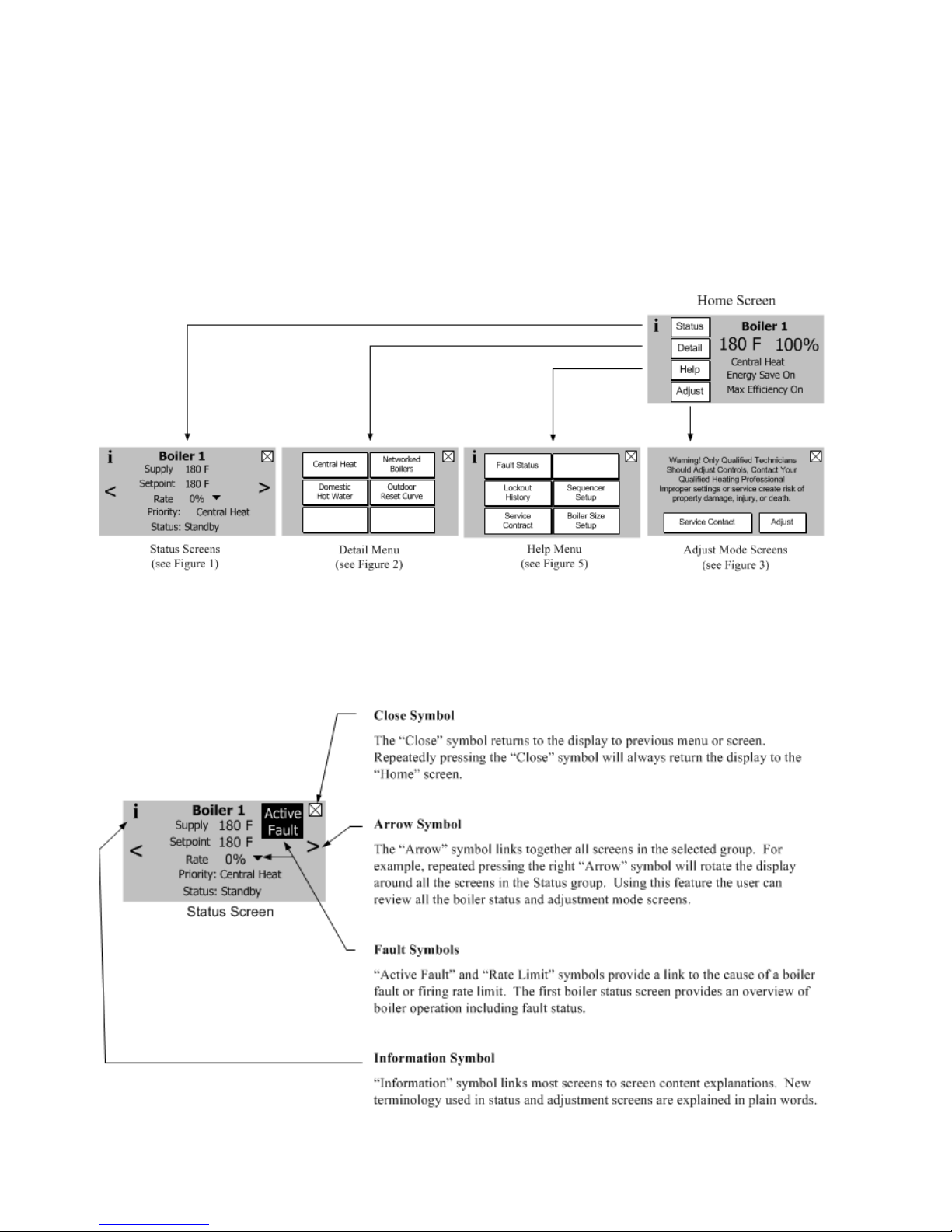
2. Using The Display
The Control includes a touch screen LCD display. The user monitors and adjusts boiler operation by selecting screen
navigation “buttons” and symbols. Navigation features are shown below.
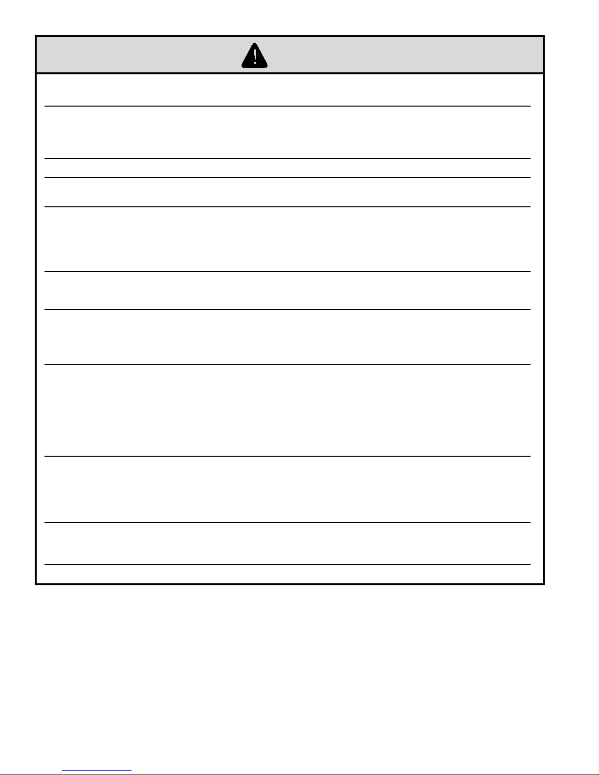
The “Home Screen” and menu selections are shown below. When no selection is made, while viewing any screen, the
display reverts to the “Home Screen” after 4 minutes. The “Home Screen” displays boiler temperature, boiler status and
Efciency Information. “Energy Save On” indication appears when the outdoor reset or setback features have lowered the
Central Heat Setpoint based on outside air temperature measurement or time of day. “Max Efciency On” appears when
the boiler return temperature has been reduced low enough to allow energy saving ue gas condensation.
Home Screen
The Home Screen Menu Buttons connect the displays four main display groups; Status, Detail,
Help and Adjustment Screens.
10
105337-02 - 9/14

I. Operation F. Viewing Boiler Status (continued)
F. Viewing Boiler Status
1. Status Screens
Boiler Status screens are the primary boiler monitoring screens. The user may simply “walk” though boiler
operation by repeatedly selecting the right or left “arrow” symbol. These screens are accessed by selected the
“Status” button from the “Home” screen.
Figure 1: Status Screens
105337-02 - 9/14
11

1. Status Screens (continued)
Central Heat
On Point - 7 F
Setpoint
Off Point +
5 F
Firing Rate 22%
Setpoint: Outdoor Reset
i
180 F
180 F
Supply
Outdoor Reset
Outside Air
W
a
t
e
r
180
130
110
0 70
i
Setpoint 164 F
Outside Air 16 F
Status: Enabled
I. Operation F. Viewing Boiler Status (continued)
Data Logging
Real time graphic trends allow users to observe process
changes over time providing valuable diagnostic
information. For example, ame current performance
over start up periods and varying loads can be an indication
of gas supply issues. Additionally, supply and return
temperature dual pen trends brings a focused look at
heat exchanger and pump performance. For example,
studying a differential temperature trend may indicate
pump speed settings need to be changed.
Pump Status/Cycles
i
System On 98
Boiler On 23
DHW Off 0
Frost Protection On Exercise On
><
Pumping is a major part of any hydronic system. This screen
provides the status of the boiler’s demand to connected
pumps as well as the status of Frost Protection and pump
Exercise functions.
Cycles and Hours
Boiler cycles and hours are used to monitor the
boilers overall compatibility to the heating load.
Excessive cycling compared to run time hours
may be an indication of pumping, boiler sizing or
adjustment issues.
Heat Demand
i
Central Heat On
Domestic Hot Water Off
Sequence Master Off
Frost Protection Off
><
This screen provides the status of the boiler’s 4 possible
heat demands. When demand is off the Control has not
detected the call-for-heat.
2. Detail Screens
Detail screens are accessed by selected the
“Detail” button from the “Home” screen and
provide in depth operating parameter status
such as “On Point”, “Off Point” and Setpoint
Source information.
Detail screens are provided for Central Heat
(shown), DHW and Sequencer demands.
12
Outdoor Reset saves energy and improves home comfort
by adjusting boiler water temperature . This screen
presents the active reset curve. The curve shows the
relationship between outside air and outdoor reset
setpoint. The curve shown is adjustable by entering the
display’s adjust mode.
Figure 1: Detail Screens
105337-02 - 9/14

I. Operation F. Viewing Boiler Status (continued)
3. Multiple Boiler Sequencer Screens
When the Sequence Master is enabled the following screens are available:
105337-02 - 9/14
13

I. Operation G. Changing Adjustable Parameters (continued)
G. Changing Adjustable Parameters
1. Entering Adjust Mode
The Control is factory programmed
to include basic modulating boiler
functionality. These settings are password
protected to discourage unauthorized or
accidental changes to settings. User login is
required to view or adjust these settings:
- Press the “Adjust” button on the “Home”
screen.
- Press the “Adjust” button on the Adjust
Mode screen or Press “Service Contact”
for service provider contact information.
- Press “Login” button to access password
screen.
- Press 5-digit display to open a keypad.
Enter the password (Installer Password
is 86) and press the return arrow to close
the keypad. Press the “Save” button.
- Press the “Adjust” button to enter
Adjustment mode.
Figure 2: Adjust Mode Screens
2. Adjusting Parameters
Editing parameters is accomplished as follows:
i
<
Accept Value
Press the button to confirm
newly edited value.
The value modified with the
increase and decrease buttons is
not accepted unless this button is
also pressed
Edit Value
Press the buttons to edit a
value. While editing a value it will blink
until it has been accepted or cancelled. A
value is also cancelled by leaving the
screen without accepting the value.
Central Heat
CH Setpoint
F
180
Value to be edited
(blinks while editing)
>
Cancel edit
Press the button to cancel
newly edited value and go back
to the original
14
105337-02 - 9/14

I. Operation G. Changing Adjustable Parameters (continued)
Pump
Setup
- More -
Manual
Control
Contractor
Setup
System
Setup
Modulation
Setup
Outdoor
Reset
Remote
4-20mA
Central
Heat
Domestic
Hot Water
Sequence
Master
Sequence
Slave
System
Setup
2. Adjusting Parameters (continued)
From the “Home” screen select the Adjust button to access the adjustment mode screens show below (if required, refer to
the previous page to review how to enter Adjustment mode):
The following pages describe
the Control’s adjustable parameters.
Parameters are presented in the order
they appear on the Control’s Display,
from top to bottom and, left to right
“Press”
Factory
Setting
Fahrenheit
4 0-14
8 0-14
Wired
Enabled Enable/Disable
0 Secs 0-900 Secs
Disabled Enable/Disable
70°F 0-100°F
Fahrenheit,
Not Installed,
Wireless
Range /
Choices
Celsius
Wired
button to access the following parameters:
Parameter and Description
Temperature Units
The Temperature Units parameter determines whether temperature is represented in units of
Fahrenheit or Celsius degrees.
Display Brightness
Display brightness is adjustable from 0 to 14.
Display Contrast
Display contrast is adjustable from 0 to 14.
Outdoor Sensor Source
Not Installed Outdoor Sensor is not connected to the boiler, the sensor is not monitored for faults.
Wired Outdoor Sensor is installed directly on the boiler terminal Strip-TB2.
Wireless Outdoor sensor is installed and wireless.
Frost Protection
Disable Frost Protection is not used.
Enable Boiler and system circulators start and boiler res when low outside air, supply and
return temperatures are sensed as follows:
Anti-Short Cycle Time
Anti-short cycle is a tool that helps prevent excessive cycling resulting from a fast cycling
Thermostat or Zone valves. It provides a minimum delay time before the next burner cycle. DHW
demand is serviced immediately, without any delay.
Warm Weather Shutdown Enable
Disable Warm Weather Shutdown (WWSD) is not used.
Enable The boiler will not be allowed to start in response to a central heat call for heat if the
outside temperature is greater than the WWSD setpoint. WWSD is initiated as soon
as outside air temperature is above WWSD Setpoint. The control does not require
call for heat to be satised.
The boiler will still start in response to a Domestic Hot Water call for heat.
Warm Weather Shutdown Setpoint
The Warm Weather Shutdown (WWSD) Setpoint used to shutdown the boiler when enabled by the
“WWSD Enable” parameter.
Device
Started
Boiler & System Outside Air < -22°F (-30°C) Outside Air > -18°F (-28°C)
Start
Temperatures
Stop
Temperatures
105337-02 - 9/14
15

Modulation
Setup
I. Operation G. Changing Adjustable Parameters (continued)
2. Adjusting Parameters (continued)
WARNING
Asphyxiation Hazard. Boiler type is factory set and must match the boiler model. Only change the boiler
type setting if you are installing a new or replacement Control. The boiler type setting determines minimum
and maximum blower speeds. Incorrect boiler type can cause hazardous burner conditions and improper
operation that may result in PROPERTY LOSS, PHYSICAL INJURY OR DEATH.
“Press”
Factory
Setting
See Table
4
See Table
4
See Table
4
See Table
4
See Table
4
button to access the following parameters:
Range / Choices Parameter and Description
Boiler Type
Boiler Size Setup
To verify the boiler size selection, a qualied technician should do the following:
1. Check boiler’s label for actual boiler size.
See Table 4
Minimum to
Maximum
Modulation
Minimum to
Maximum
Modulation
Minimum
- 100 to
Maximum
See Table 4
2. Set “Boiler Type” to match actual boiler size.
3. Select “Conrm”.
The Boiler Type parameter changes the minimum and maximum modulation settings. This
parameter is intended to allow a user to set the parameters in a spare part Control to a particular
boiler type.
Central Heat Maximum Modulation
This parameter denes the highest modulation rate the Control will go to during a central heat call
for heat. If the rated input of the installed home radiation is less than the maximum output of the
boiler, change the Central Heat Maximum Modulation (fan speed) setting to limit the boiler output
accordingly.
Domestic Hot Water (DHW) Max Modulation
This parameter denes the highest modulation rate the Control will go to during a Domestic Hot
Water call for heat. If the rated input of the indirect water heater is less than the maximum output
of the boiler, change the DHW Maximum Modulation (fan speed) setting to limit the boiler output
accordingly.
Minimum Modulation
This parameter is the lowest modulation rate the Control will go to during any call for heat.
Lightoff Rate
This is the blower speed during ignition and ame stabilization periods.
Table 4: Parameters Changed Using the Boiler Type Parameter Selections:
Control Repair Part P/N 105439-01
Altitude 0 - 2000 Ft.
Boiler Type K2-80-02 K2-100-02 K2-120-02 K2-150-02 K2-180-02
Maximum Modulation Rate (RPM) 5100 5500 5100 5400 6000
Minimum Modulation Rate (RPM) 1600 1650 1600 2000 1800
Absolute Maximum Modulation Rate (RPM) 5400 6900 5700 6300 6700
Minimum Light-off Rate (RPM) 3500 3500 3500 3500 3500
Maximum Light-off Rate (RPM) 4000 4000 4000 4000 4000
NOTE: Maximum Modulation Rates are designed for 100% nameplate rate at 0°F (-18°C) combustion air. Contact factory before
attempting to increase the Maximum Modulation Rate.
16
105337-02 - 9/14

Pump Setup
I. Operation G. Changing Adjustable Parameters (continued)
“Press”
Factory Setting Range / Choices Parameter and Description
Central Heat,
Optional Priority
Any Demand
Primary
Loop Pipe
IWH
button to access the following parameters:
System Pump run pump for:
Activates the system pump output according to selected function.
Never,
Any Demand,
Central Heat,
No Priority,
Central Heat,
Optional Priority
Any Demand
Never,
Primary Loop
Piped IWH,
Never: Pump is disabled and not shown on status screen.
Any Demand: Pump Runs during any call for heat.
Central Heat, No Priority: Pump Runs during central heat and frost protection call for
heat. Pump does not start for a DHW call for heat and
continues to run during Domestic Hot Water Priority.
Central heat, Optional
Priority: Pump Runs during central heat and frost protection call for
heat. Pump does not start for a DHW call for heat and will be
forced off if there is a DHW call for heat and Domestic Hot
Water Priority is active.
Boiler Pump run pump for:
Activates the boiler pump output according to selected function. This feaature is not
adjustable.
Any Demand: Pump Runs during any call for heat.
Domestic Pump run pump for:
Activates the Domestic pump output according to selected function.
Never: Pump is disabled and not shown on status screen.
Primary Loop Piped IWH: Pump Runs during domestic hot water call for
heat. Domestic Hot Water Priority enable/disable
does not affect pump operation.
Example Pump Parameter selections:
Single boiler with no Indirect Water Heater
Parameter Selection:
System pump = “Central Heat,
Optional Priority”
Boiler pump = “any demand”
DHW pump = “never”
Explanation:
This piping arrangement only
services central heat. When
there is any demand both
boiler and system pumps turn
on.
105337-02 - 9/14
17

I. Operation G. Changing Adjustable Parameters (continued)
Example Pump Parameter selections (continued):
Single boiler Indirect Water Heater (IWH)Piped to Primary, Optional Domestic Hot Water Priority.
Parameter Selections:
System Pump = “Central Heat,
Optional Priority”
Boiler Pump = “any demand”
DHW Pump = “Primary Loop Piped IWH”
DHW Priority Enable is optional
Explanation:
This piping arrangement permits the
system pump to run or not run when
there is a domestic hot water call for heat.
Domestic hot water priority is optional.
It is permissible for the domestic and
system pumps to run at the same time.
The boiler pump must run for every call
for heat.
Multiple Boilers with Boiler Piped IWH, System and DHW Wired to Master
Wiring locations:
Thermostat X
DHW call for heat X
System pump X
DHW pump X
Boiler Pump X X
Sequencer Master Parameter Selections:
Sequencer Master Enabled
Indirect Water
Heater
Pump Parameter Selections:
System Pump =
Boiler Pump = Any demand
DHW Pump = “Primary Piped” Never
Sequencer
Master
(Boiler 1)
“Boiler Piped”
Central Heat,
No Priority
Boiler 2
Never
Any
demand
Explanation:
When call for Domestic Hot Water is received the DHW pump is turned on and the boiler pump is turned on. However, the system
pumps may run to satisfy a central heat demand that is being satised by a different slave. The central heat demand is ignored by
Slave 1 until the domestic hot water demand is ended.
18
105337-02 - 9/14

I. Operation G. Changing Adjustable Parameters (continued)
Example Pump Parameter selections (continued):
Multiple boilers IWH Piped to Primary, Optional Domestic Hot Water Priority
Sequencer Master
(Boiler 1)
Wiring locations:
Thermostat X
DHW call for heat X
System pump X
DHW pump X
Boiler Pump X X
Sequencer Master Parameter Selections:
Sequencer Master Enabled
Indirect Water
Heater
Pump Parameter Selections:
System Pump =
Boiler Pump = Any demand
DHW Pump =
Explanation:
This piping arrangement permits the system pump to run or not run when there is a domestic hot water call for heat. Domestic hot water
priority is optional. It is permissible for the domestic and system pumps to run at the same time. The boiler pump must run for every call for
heat.
“Primary Piped”
Central Heat,
Optional Priority
Primary Loop
Piped IWH
Boiler 2
Never
Any
demand
Never
Multiple Boilers, IWH piped to primary, system pump required to run for any call for heat
Sequencer Master
(Boiler 1)
Wiring locations:
Thermostat X
DHW call for heat X
System pump X
DHW pump X
Boiler Pump X X
Sequencer Master Parameter Selections:
Sequencer Master Enabled
Indirect Water
Heater
Pump Parameter Selections:
System Pump = Any demand Never
Boiler Pump = Any demand Any demand
DHW Pump =
Explanation:
This piping arrangement requires the system pump to be running for any calls for heat. Also the boiler pump must run for any call for heat.
“Primary Piped”
Primary Loop
Piped IWH
Boiler 2
Never
105337-02 - 9/14
19

Contractor
Setup
I. Operation G. Changing Adjustable Parameters (continued)
Manual
Control
“Press”
button to access the following parameters:
i
<
Use Up and DOWN Arrows for More
Exit Screen without Saving
Contractor Name
Press box to input contractor information.
Bill Smith
Save
Press SAVE button to store revisions.
Enter Contractor Information
Bill Smith
2
3
1
A
4
B
C
D
Clear Entire Field
Backspace
Save Field and Exit
5
For Service Contact:
Bill Smith
>
12 Victory Lane
Plainview, New York
516 123-4567
Example Screen
8
7
8
6
7
CL
ES
BS
R
C
Factory Setting Range / Choices Parameter and Description
Contractor Name User dened Contractor Name
Address Line 1 User dened Contractor Address Line 1
Address Line 2 User dened Contractor Address Line 2
Phone User dened Contractor Phone
“Press”
button to access the following screen:
The Manual Speed Control speed screen allows the technician to set ring rate at low or high speed for combustion testing.
Manual Speed Control
i
0 RPM 0%
Status Auto
press to change mode
High
Low
Auto
Selecting “Low” or “High”
locks (manual mode) firing
rate at min or max Rate %.
After combustion testing select
“Auto” to return the boiler to
NOTE
normal operation.
“Press” “Low” to select
manual firing rate control
and Minimum firing rate %
20
“Press” “High” to select
manual firing rate control
and Central Heat
Maximum firing rate %
Press “Auto”
to return
firing rate to
Automatic
Mode
105337-02 - 9/14

“Press”
Central
Heat
I. Operation G. Changing Adjustable Parameters (continued)
button to access the following parameters:
Factory
Setting
180°F
(82.2°C)
170°F
(76.7°C)
7°F
(3.9°C)
5°F
(2.8°C)
120
seconds
Range / Choices Parameter and Description
60°F to 190°F
(16°C to 87.8°C)
60°F to 190°F
(16°C to 87.8°C)
(1.1°C to 5.6°C)
(1.1°C to 14°C)
3 1 to 5
0 to 300 seconds
2°F to 10°F
2°F to 25°F
Central Heat Setpoint
Target temperature for the central heat priority. Value also used by the outdoor air reset function.
Central Heat Thermostat “Sleep” or “Away” Setback Setpoint
Thermostat setback setpoint is used when the EnviraCOM thermostat is in “leave” or “sleep”
modes and sensed at E-COM terminals D, R, and C. When setback is “on” the thermostat setback
setpoint shifts the reset curve to save energy while home is in a reduced room temperature mode.
The reset curve is shifted by the difference between the High Boiler Water Temperature and the
Thermostat Setback Setpoint. Honeywell VisionPro IAQ part number TH9421C1004 is a “setback”
EnviraCOM enabled thermostat. When connected, it allows boiler water setback cost savings.
Central Heat Diff Above
The boiler stops when the water temperature rises ‘Diff Above’ degrees above the setpoint.
Central Heat Diff Below
The boiler starts when the water temperature drops ‘Diff Below’ degrees below the setpoint.
Response Speed
This parameter adjusts the Central Heat temperature controller Proportion Integral Derivative
(PID) values. Higher values cause a larger ring rate change for each degree of temperature
change. If set too high ring rate “overshoots” required value, increases to high re causing the
temperature to exceed the “Diff Above” setpoint and cycle the boiler unnecessarily. Lower values
cause a smaller ring rate change for each degree of temperature change. If set too low, the ring
rate response will be sluggish and temperature will wander away from setpoint.
Low Fire Hold Time
“Low Fire Hold Time” is the number of seconds the control will wait at low re modulation rate
before being released to modulate. After ignition and ame stabilization periods the ring rate is
held at low re for “Low Fire Hold Time”. This delay allows heat to travel out to the system and
provide system feedback prior to the control modulating ring rate.
Supply
Sensor
Supply Sensor,
Header Sensor
Modulation Sensor
Heat Demand may respond to the boiler’s Supply Temperature or Header Temperature sensors.
When Header Sensor is selected the boiler is red in response to the sensor wired to Header
Sensor Low Voltage Terminal Block Terminals.
105337-02 - 9/14
21

Domestic
Hot Water
I. Operation G. Changing Adjustable Parameters (continued)
“Press”
Factory
Setting
170°F
(76.7°C)
160°F
(71.1°C)
7°F
(3.9°C)
5°F
(2.8°C)
10
seconds
Enable Enable Disable
Range / Choices Parameter and Description
60°F to 190°F
(16°C to 87.8°C)
60°F to 190°F
(16°C to 87.8°C)
(1.1°C to 5.6°C)
(1.1°C to 14°C)
3 1 to 5
0 to 300 seconds
30 to 120 Minutes
button to access the following parameters:
2°F to 10°F
2°F to 25°F
Domestic Hot Water Setpoint
The Domestic Hot Water (DHW) Setpoint parameter is used to create a minimum boiler water
temperature setpoint that is used when DHW heat demand is “on”.
When the DHW heat demand is not “on” (the contact is open or not wired) this setpoint is ignored.
Domestic Hot Water Thermostat “Sleep” or “Away” Setback Setpoint
Thermostat setback setpoint is used when the EnviraCOM thermostat is in “leave” or “sleep”
modes and sensed at E-COM terminals D, R, and C. When setback is “on” the thermostat
setback setpoint shifts the DHW setpoint to lower the DHW temperature and to save energy
while home is in a reduced room temperature mode.
Domestic Hot Water Diff Above
The boiler stops when the water temperature rises ‘Diff Above’ degrees above the setpoint.
Domestic Hot Water Diff Below
The boiler starts when the water temperature drops ‘Diff Below’ degrees below the setpoint.
Response Speed
This parameter adjusts the Domestic Hot Water temperature controller Proportion Integral
Derivative (PID) values. Higher values cause a larger ring rate change for each degree of
temperature change. If set too high ring rate “overshoots” required value, increases to high re
causing the temperature to exceed the “Diff Above” setpoint and cycle the boiler unnecessarily.
Lower values cause a smaller ring rate change for each degree of temperature change. If set
too low, the ring rate response will be sluggish and temperature will wander away from setpoint.
Low Fire Hold Time
“Low Fire Hold Time” is the number of seconds the control will wait at low re modulation rate
before being released to modulate. After ignition and ame stabilization periods the ring rate is
held at low re for “Low Fire Hold Time”. This delay allows heat to travel out to the indirect water
heater and provide feedback prior to the control modulating ring rate
Domestic Hot Water Priority (DHWP)
When Domestic Hot Water Priority is Enabled and Domestic Hot Water (DHW) heat demand is
“on” the DHW demand will take “Priority” over home heating demand. When the System and
Boiler pumps are congured as “Central Heat (off DHW priority)” or “Central Heat, Optional
Priority” then they will be forced “off” during DHW Priority. Priority protection time is provided to
end DHWP in the event of a failed or excessive long DHW demand.
Priority Time
When DHWP is Enabled the Priority Time Parameter appears and is adjustable.
.
22
105337-02 - 9/14

I. Operation G. Changing Adjustable Parameters (continued)
Outdoor
Reset
“Press”
Factory
Setting
Enabled Enable Disable
0°F
(-18°C)
70°F
(21.1°C)
110°F
(43.3°C)
130°F
(54.4°C)
20 Minutes
Range / Choices Parameter and Description
(-40°C to 37.8°C)
(21.1°C to 87.8°C)
(26.7°C to 87.8°C)
button to access the following parameters:
-40°F to 100°F
32°F to 100°F
(0°C to 37.8°C)
70°F to 190°F
80°F to 190°F
0-1800 Seconds
(0-30 Minutes)
Outdoor Reset Enable
If an outdoor sensor is installed and Outdoor Reset is Enabled, the boiler will automatically
adjust the heating zone set point temperature based on the outdoor reset curve in Figure
2. The maximum set point is dened by the Central Heat Setpoint [factory set to 180°F
(82.2°C)] when the outdoor temperature is 0°F (-18°C) or below. The minimum set point
temperature shown is 130°F (54.4°C) [adjustable as low as 80°F (26.7°C)] when the
outdoor temperature is 50°F (10°C) or above. As the outdoor temperature falls the supply
water target temperature increases. For example, if the outdoor air temperature is 30°F,
(-1.1°C) the set point temperature for the supply water is 150°F (65.6°C).
Disable Do Not Calculate setpoint based on outdoor temperature
Enable Calculate the temperature setpoint based on outdoor temperature using a reset
curve dened by Low Outdoor Temp, High Outdoor Temp, Low Boiler Water
Temp, Min Boiler Temp and Central Heat Setpoint and Boost Time parameters.
Low Outdoor Temperature
The Low Outdoor Temperature parameter is also called “Outdoor Design Temperature”.
This parameter is the outdoor temperature used in the heat loss calculation. It is typically
set to the coldest outdoor temperature.
High Outdoor Temperature
The High Outdoor Temperature parameter is the outdoor temperature at which the Low
Boiler Water Temperature is supplied. This parameter is typically set to the desired building
temperature.
Low Boiler Water Temperature
The Low Boiler Water Temperature parameter is the operating setpoint when the High
Outdoor Temperature is measured. If the home feels cool during warm outdoor conditions,
the Low Boiler Water Temperature parameter should be increased.
Minimum Boiler Temperature
The Minimum Boiler Temperature parameter sets a low limit for the Reset setpoint. Set this
parameter to the lowest supply water temperature that will provide enough heat for the type
radiation used to function properly. Always consider the type of radiation when adjusting
this parameter.
Boost Time
When the Central Heat Setpoint is decreased by Outdoor Reset settings, the Boost Time
parameter is used to increase the operating setpoint when the home heat demand is not
satised after the Boost Time setting is exceeded. When heat demand has been “on”
continuously for longer than the Boost Time parameter the operating setpoint is increased
by 10°F (5.6°C). The highest operating setpoint from Boost Time is current Central Heat
Setpoint minus the Central Heat “Diff Above” setting. A setting of 0 seconds disables this
feature.
105337-02 - 9/14
23

Outdoor Air Temperature
-20 105-15 -10 -5
0
110
454020 25 30 35 55 60 65
70
15 50
145
115
150
120
140
135
130
125
155
190
160
195
165
185
180
175
170
200
Boost Maximum Off Point
= Central Heat Setpoint
minus Diff Above
Low Boiler Water Temp
Default = 110 F
High Outside Air Temp
Default = 70 F
10 F
Hot Water Setpoint
Minimum Water Temperature
Default = 130 F
TOD Setback Setpoint
Default = 170 F
Central Heat Setpoint
Low Outside Air Temp
=180 F & 0 F
Default Outdoor Air Reset Setpoint
(Shown Bold)
Default Boost Outdoor Air Reset Setpoint
(Shown with thin lines, typical)
(Reset setpoint increased by 10 F every
20 minutes that demand is not satisfied.
Boost Time is field selectable
between 0 to 30 minutes)
75
I. Operation G. Changing Adjustable Parameters (continued)
Central Heat
Setpoint
180°F to 190°F
(82.2°C to 87.8°C)
160°F to 190°F
(71.1°C to 87.8°C)
130°F to 160°F
(54.4°C to 71.1°C)
24
Figure 4: Outdoor Reset Curve
Heating Element Type
Fan Coil
Convection
Baseboard
Fin Tube
Convective
Radiant
Baseboard
Central Heat
Setpoint
100°F to 140°F
In Slab Radiant High
(37.8°C to 60°C)
130°F to 160°F
(54.4°C to 71.1°C)
140°F to 160°F
(60°C to 71.1°C)
Heating Element Type
Mass Radiant
Staple-up Radiant
Low Mass Radiant
Radiators
105337-02 - 9/14

I. Operation G. Changing Adjustable Parameters (continued)
Sequence
Master
Sequence
Slave
“Press” button to access the following parameters:
Factory
Setting
Local
Local
130°F
(54.4°C)
180°F
(82.2°C)
* Only visible when Central Heat Setpoint Source is set to 4-20mA.
Range /
Choices
Local,
4-20mA
Local,
4-20mA
80°F (26.7°C) -
Central Heat
Setpoint
80°F (26.7°C) -
Central Heat
Setpoint
Central Heat Modulation Source
This parameter enables the 4-20mA input to control ring rate and the thermostat input to control boiler on/off
demand directly without using the internal setpoint. The 4-20mA selection is used to enable a remote multiple boiler
controller to control the Sage2.1 Control:
Local: 4-20mA Input on Terminal 9 & 10 is ignored.
4-20mA 4-20mA Input on Terminal 9 & 10 is used to control ring Rate % directly.
Central Heat Setpoint Source
Sets the remote (Energy Management System) control mode as follows:
Local: Local setpoint and modulation rate is used. 4-20mA input on Terminal 9 & 10 is ignored.
4-20mA 4-20mA Input on Terminal 9 & 10 is used as the temperature setpoint. The following two
parameters may be used to adjust the signal range.
Central Heat 4-20mAdc Setup, 4 mA Water Temperature*
Sets the Central Heat Temperature Setpoint corresponding to 4mA for signal input on terminal 9 & 10. Current
below 4mA is considered invalid, (failed or incorrect wired input).
Central Heat 4-20mAdc Setup, 20 mA Water Temperature*
Sets the Central Heat Temperature Setpoint corresponding to 20mA for signal input on terminal 9 & 10. Current
above 20mA is considered invalid, (failed or incorrect wired input).
Parameter and Description
“Press”
Factory
Setting
Disable
Boiler
Piped
Disabled
180 Secs 120 - 1200 Secs
195°F
(90.6°C)
70% 50% - 100%
3 1-5
Range / Choices Parameter and Description
Enable,
Disable
Boiler Piped,
Primary Piped
Enable,
Disable
Central Heat
Setpoint,
195°F (90.6°C)
button to access the following parameters:
Master Enable/Disable
The Sequencer Master Enable/Disable is used to “turn on” the Multiple Boiler Controller. Warning! enable
ONLY one Sequence Master.
Indirect Water Heater (IWH)
Boiler Piped Sequencer to respond to an Isolated DHW demand that is piped to a single boiler. The
individual boiler goes on “Leave” from the Sequencer Master and goes to DHW Service.
Primary Piped The Sequence Master responds to the DHW Call For Heat. This allows one or more
boilers to provide heat to the IWH.
DHW Two Boiler Start
The Sequencer to immediately start two boilers for a DHW call for heat. Used when DHW is the largest
demand. Only visible when primary piped IWH is selected.
Boiler Start Delay
Slave boiler time delay after header temperature has dropped below the setpoint minus “Diff below” setpoint.
Longer time delay will prevent nuisance starts due to short temperature swings.
Stop All Boilers Setpoint
When this temperature is reached all boilers are stopped. This setpoint allows the Sequencer to respond to
rapid load increases.
Base Load Common Rate
To maximize condensing boiler efciency, the ring rate is limited to an adjustable value. Boilers are kept at
or below this ring rate as long as the boilers can handle the load. After last available boiler has started, the
modulation rate limit is released up to 100%.
Response Speed
This parameter adjusts the Sequence Master temperature controller Proportion Integral Derivative (PID)
values. Higher values cause a larger ring rate change for each degree of temperature change. If set too
high ring rate “overshoots” required value, increases to high re causing the temperature to exceed the “Diff
Above” setpoint and cycle the boiler unnecessarily. Lower values cause a smaller ring rate change for each
degree of temperature change. If set too low, the ring rate response will be sluggish and temperature will
wander away from setpoint.
“Press”
Factory
Setting
None 1-8
Normal
Range / Choices Parameter and Description
Use Boiler First,
Normal,
Use Boiler Last
button to access the following parameters:
Boiler Address
Each boiler must be given a unique address. When ”Normal” slave selection order is used, the boiler address
is used by the Master Sequencer as the boiler start order. The boiler address is also the Modbus Address
when a Energy Management System is connected.
Slave Selection Order
“Use Boiler First”; places the Slave in the lead permanently.
”Normal”; ring order follows boiler number (1,2,3,..) order.
”Use Boiler Last”; places the slave last in the ring order.
105337-02 - 9/14
25

II. Troubleshooting
WARNING
Electrical Shock Hazard. Turn off power to boiler before working on wiring.
A. Troubleshooting problems where no error code is displayed.
Condition Possible Cause
Boiler not responding to call for heat, “Status” and
“Priority” show “Standby”.
Boiler not responding to a call for heat, “Status”
shows “Standby” and “Priority” shows Central Heat
or Domestic Hot Water.
Boiler Running but System or Boiler Circulator is
not running
Home is cold during mild weather days • Increase Low Boiler Water Temperature parameter 5°F (2.8°C) per day.
Home is cold during cold weather days • Increase High Boiler Water Temperature parameter 5°F (2.8°C) per day
B. Display Faults:
Faults are investigated by selecting the “Help” button from the “Home” screen. When a fault is active the “Help” button ashes
and the home screen turns a red color. Continue to select ashing buttons to be directed to the Fault cause.
Boiler is not seeing call for heat. Check thermostat or zone wiring for loose connection,
miswiring, or defective thermostat/zone control.
Boiler is not ring, temperature is greater than setpoint. Water ow through boiler primary
loop non-existent or too low.
• Check wiring for loose connection, miswiring.
• When there is a Domestic Hot Water Heat Request the System or Boiler pumps will be
forced “off” when there “Run Pump for” parameter is set to “Central heat, off DHW
demand” or “Central Heat, Optional Priority”. This has been set to allow all of the heat
to be provided for fast indirect water heater recovery. After one hour of “priority
protection” or the end of the Domestic Hot Water Heat Request the system and boiler
pumps will be free to run.
Home Screen
Status
i
Detail
Standby
Help
Energy Save On
Max Efficiency On
Adjust
Boiler
024 F
**00FF
Communication
Fault
Sensor
Fault
i
Lockout
History
Service
Contract
Active Faults
Sequencer
Boiler Size
Help Screen
Indication Condition Possible Cause
Display Completely Dark
Fan off, LWCO lights off, no green power
light on Control
Display Completely Dark, Fan running No 24Vac
Blinking Green power light on Control Control
Display Completely Dark but Boiler res No 5 Vdc
**00FF display lost
ER0011 Adjustment
No 120Vac Power
at Boiler
Power to Control
Fault
Power to Display
communication
with control
Mode Password
Timeout
Setup
Setup
Figure 5: Help Menu
Check breaker and wiring between breaker panel and boiler.
- Blown high voltage fuse, Replacement Fuse Kit, part number 105349-01.
- Loose 120Vac connection wiring between boiler J-Box and transformer
- Loose 24 Vac connection wiring between transformer and Control.
- Blown low voltage fuse, Replacement Fuse Kit, part number 105349-01.
- The green light is connected to internal power supply. The power supply
is repeatedly starting and stopping (not normal) making the light ash. The
microprocessors are not running.
- Try disconnecting all terminals except 24VAC to power the Control. The
green light should be steady. If it is not, then the control is defective. If steady,
start plugging in all the connectors while watching the green light.
When faulty wiring reconnected, green light will begin to ash.
- Loose 5 Vdc connection wiring between display and Control
- Defective Display or Control.
- Loose or defective display harness
- Defective Display
- Defective Control
- The Control and Display are NOT defective. The password has timed out.
Simply cycle power to the Display to restore operation.
i
Soft Lockout
Limit String
Rate Limit
(Hold)
Status
Status
Active Fault Screen
Lockout
Hard
Sensor
Status
Reset
26
105337-02 - 9/14

II. Troubleshooting (contined)
Sequencer
Setup
Boiler Size
Setup
C. Help Screen Faults
Indication Condition Possible Cause
This alarm is active if the slave boiler has lost communication with the Sequence Master. Check
the following:
- RJ 45 peer-to-peer network disconnected
- Sequencer Master was Enabled and then Disabled
- Master’s Boiler has been powered down.
- To clear fault restore communication or cycle power
Boiler size setting may not match actual boiler size.
The Boiler size setting determines min, max and light-off blower speeds. Incorrect boiler size can
cause hazardous burner conditions and improper operation that may result in PROPERTY LOSS,
PHYSICAL INJURY, OR DEATH.
Refer to page 16 for boiler size setting instructions.
Flashing
Flashing
Sequencer
Setup
Fault
Boiler
Size
Fault
D. Help Screen Diagnostic Features
Indication Possible Cause
Lockout History is stored in a rst-in, rst-out basis. Each History le is stored with boiler run hour of when the
lockout occurred.
For Service Contact:
CONTRACTOR NAME
CONTRACTOR ADDRESS 1
CONTRACTOR ADDRESS 2
PHONE NUMBER
The “When happened” and “Current” provide:
- “Current” is the run hour and status the boiler just nished.
- “When happened” is the run hour and status when the lockout occurred.
The user is given the contact information of the responsible service provider. Refer to page 20 for data entry
instructions.
WARNING!
E. Active Fault Screen Faults
Indication Condition Possible Cause
The Limit String Status screen shows the safety limit status. A contact icon, either “open” or
Limit String Status
Limit String Status
i
Limits Flow Switch
Air Proving Switch
Sensor Status
i
Supply Sensor 180 F Normal
Return Sensor 768 F Shorted
Stack Sensor 024 F Open
Outdoor Sensor 45 F Normal
Header Sensor None
4-20mA Input 4 mA Normal
Rate Limit
Rate Limits
i
Active Rate Limiter:
High Stack Temp Rate Limit
Active Rate Override:
Burner Control Rate Override
Limit String
Fault
Sensor
Fault
High Stack
Temperature
Rate Limit
“closed”, graphically represents each safety limit. The “closed” contact icon is steady; the “open”
contact icon is blinking. For example, the screen shown to the left illustrates a “closed” Limit
contact and an “open’ Flow Switch and Air Proving Switch Limit contacts.
NOTE: Since the limit string items are wired in series, all limits downstream of the “open” limit will
also appear on the screen as “open” (blinking) icons regardless of whether or not they are actually
open. The Air Proving Switch is wired independent to all other limits.
The Sensor Status screen shows the status of all sensors. Possible states include:
None: Feature requiring this sensor has not been selected.
Normal: Sensor is working normally.
Shorted: Sensor is shorted or is defective.
Open: There is a break in the wiring between the Control and the sensor or the sensor is
defective
Out of Range: Sensor is defective or is being subjected to electrical noise.
Unreliable: Sensor is defective or is being subjected to electrical noise.
When a sensor fails “opened” or “shorted” the value is changed to reverse video (background
black and value white) “024” or “768” respectively to indicate that there is a fault with the sensor.
The following messages appear when the ring rate is limited or reduced to help avoid a lockout.
Refer to lockout section for potential corrective action.
- High Stack Temperature Limit
- High Supply Temperature Limit
- High Differential Temperature Limit
The following messages appear as part of a normal start and stop sequence:
- Minimum Modulate (normal start/stop sequence)
- Forced Modulation (normal start/stop sequence)
- Burner Control Rate (normal start/stop sequence)
- Manual Firing Rate ( User selection)
- Low Fire Hold (user selection)
105337-02 - 9/14
27

II. Troubleshooting (contined)
F. Troubleshooting problems where a Soft Lockout Code is displayed. When a soft lockout occurs, the
boiler will shut down, the display will turn red and the “Help” button will “blink”. Select the “blinking” “Help” button to
determine the cause of the soft lockout. The boiler will automatically restart once the condition that caused the lockout is
corrected.
Soft Lockout Codes Displayed
Lockout
Number
1
Anti Short Cycle
2
Boiler Safety Limit
Open
3
Boiler Safety Limit
Open
7
Return sensor
(10 KOhms) fault
8
Supply sensor
(10 KOhms) fault
9
DHW sensor fault
10
Stack sensor
(10 KOhms) fault
11
Ignition failure
Condition Possible Cause
Minimum time between starts has not been
reached. Normal delay used to avoid
excessive cycles.
Boiler Safety Limit wired to terminals J6-1, 2
or 3 OPEN:
• Thermal Fuse Switch contact open.
• Air Pressure Switch contact open.
• Auto Reset High Limit contact open.
Boiler Safety Limit, or External Limit wired to
terminals J5-1 OPEN:
• Jumper for External Limit wired to
terminals 11 and 12 or device connected
to it open.
• Flow Switch contact open.
Shorted or open return temperature sensor.
Shorted or open supply temperature sensor.
Shorted or open Domestic Hot Water (DHW)
temperature sensor.
Shorted or open ue gas (stack) temperature
sensor.
Models K2-080 through K2-180 - ame
failure after 5 tries to restart.
• Flame rod not detecting ame.
• Condensate trap plugged.
• Loose wiring to limit device.
• Auto Reset Supply high limit sensor detected temperature in excess of
200°F.
• Defective Auto Reset Supply High Limit Switch.
• Thermal Fuse Switch blown due to temperature rise above 358°F.
• Air Pressure Switch contact open - check for blocked vent/air intake.
• See possible causes for “Hard Lockout 4”.
NOTE
Block Vent Special Note
Before a call for heat the air pressure switch is closed. When there is a call
for heat with a blocked vent the air pressure switch will open (due to excessive
pressure of the blower against a blocked ue pipe) after the blower starts. The
control stops the start sequence and stops the blower. After the blower stops
the pressure switch re-closes and the cycle continues. The displays shows
the cause of trip for only the time the pressure switch is open.
• See possible causes for “Hard Lockout 4”.
• Loose wiring to limit device.
• External Limit defective or jumper not installed.
• If yellow light on LWCO is on, system is low on water.
• If neither yellow or green light is on, check LWCO harness.
• Flow Switch contact open - Check for adequate ow.
• Bad Flow Switch.
• Shorted or mis-wired return sensor wiring.
• Defective return sensor.
• Shorted or mis-wired supply sensor wiring.
• Defective supply sensor.
• Shorted or mis-wired DHW sensor wiring.
• Defective DHW sensor.
• Shorted or mis-wired ue temperature sensor wiring.
• Defective ue temperature sensor.
• No gas pressure.
• Gas pressure under minimum value shown on rating plate.
• Gas line not completely purged of air.
• Defective Electrode.
• Loose burner ground connection.
• Defective Ignition Cable.
• Defective gas valve (check for 24 Vac at harness during trial for ignition
before replacing valve).
• Air-fuel mixture out of adjustment - consult factory.
• Defective or fouled electrode.
• Plugged drain line in trap.
28
105337-02 - 9/14

II. Troubleshooting (contined)
Soft Lockout Codes Displayed (continued)
Lockout
Number
13
Flame rod
shorted to ground
14
DT inlet/outlet high
15
Return temp
higher than supply
16
Supply temp has
risen too quickly
17
Blower speed
not proved
27
Interrupted Airow
Switch On
27 or 28
Interrupted Airow
Switch Off
Condition Possible Cause
• Flame rod shorted to ground
• Condensate Trap plugged.
Temperature rise between supply and return
is too high.
The Control is reading a return sensor
temperature higher than the supply sensor
temperature. Condition must be present for
at least 75 seconds for this error code to
appear.
Supply water temperature has risen too
quickly.
Normal waiting for blower speed to match
purge and light-off setpoint.
Interrupted Airow Switch Failed in closed
position
Interrupted Airow Switch Failed to Close
• Shorted or mis-wired ame rode wiring.
• Defective ame rod.
• Plugged drain line in trap.
• Inadequate boiler water ow. Verify that circulator is operating and that
circulator and piping are sized per K2 Installation Instructions Manual,
Water Piping and Trim Section.
• Flow through boiler reversed. Verify correct piping and circulator
orientation.
• No boiler water ow. Verify that system is purged of air and that appropriate
valves are open.
• Sensor wiring reversed.
• Supply or return sensor defective.
• See possible causes for “Hard Lockout 4”.
• Inadequate boiler water ow.
• Verify that circulator is operating and that circulator and piping are sized
per K2 Installation Instructions Manual, Water Piping and Trim Section.
The air proving switch has failed on, check switch is operating properly
The air proving switch has failed to close;
• Check switch, check switch connection and wiring.
• Blocked vent, blocked inlet, blocked or disconnected inlet air switch tube,
blocked heat exchanger or burner.
• Something is blocking air/ue gas ow through boiler
105337-02 - 9/14
29

II. Troubleshooting (contined)
G. Troubleshooting problems where a Hard Lockout Code is displayed. When a hard lockout occurs, the
boiler will shut down, the display will turn red and the “Help” button will “blink”. Select the “blinking” “Help” button to
determine the cause of the Hard Lockout. Once the condition that caused the lockout is corrected, the boiler will need to be
manually reset using the Reset button on the “Active Fault” display or located on the Sage2.1 Control.
Hard Lockout Codes Displayed
Lockout Number Condition Possible Cause
• Heating load at time of error was far below the minimum ring
rate of the boiler.
4
Supply high limit
5
DHW high limit
6
Stack High limit
12
Flame detected out of sequence
18
Light off rate proving failed
19
Purge rate proving failed
20
Invalid Safety Parameters
21
Invalid Modulation Parameter
22
Safety data verication needed
23
24VAC voltage low/high
24
Fuel Valve Error
25
Hardware Fault
26
Internal Fault
27
Ignition failure
27
Interrupted Airow Switch On
Sage2.1 supply sensor detected
temperatures in excess of 210°F.
Sage2.1 DHW sensor detected
temperatures in excess of Setpoint.
Sage2.1 Flue gas (Stack) sensor
detected temperatures in excess of
214°F (101°C).
A ame signal was present when there
should be no ame.
• Condensate trap plugged.
Blower is not running at Light-off rate
when it should or blower speed signal
not being detected by Sage2.1.
Blower is not running at Purge rate
when it should or blower speed signal
not being detected by Sage2.1.
Unacceptable Sage2.1 control Safety
related parameter detected.
Unacceptable Sage2.1 control
Modulation related parameter
detected.
Safety related parameter change has
been detected and a verication has
not been completed.
Sage2.1 control 24Vac control power
is high or low.
Power detected at fuel valve output
when fuel valve should be off.
Internal control failure. • Reset the control. If problem reoccurs, replace the Sage.
Internal control failure. • Reset the control. If problem reoccurs, replace the Sage.
Models K2-080 through K2-180
Flame failure after 1 try to restart.
Interrupted Airow Switch Failed to On The air proving switch has failed on, check switch is operating properly.
• Defective system circulator or no ow in primary loop.
• Defective boiler circulator, no ow or insufcient ow in boiler loop.
• Control system miswired so that the boiler operation is
permitted when no zones are calling.
• DHW load at time of error was far below the minimum ring
rate of the boiler.
• Control system miswired so that boiler operation is permitted
when no DHW are calling.
• Heat exchanger needs to be cleaned.
• Boiler over-red.
• Air-fuel mixture out of adjustment - consult factory.
• Defective gas valve - make sure inlet pressure is below
maximum on rating plate before replacing valve.
• Plugged drain line in trap.
• Loose connection in 120 VAC blower wiring.
• Loose or miswired blower speed harness.
• Defective blower
• Loose connection in 120 VAC blower wiring.
• Loose or miswired blower speed harness.
• Defective blower
Safety Parameter verication required. Contact factory.
Reset the control.
Safety related Sage2.1 control parameter has been changed and
verication has not been performed.
• Loose connection in 24Vac VAC power wiring.
• Loose or miswired 24Vac harness.
• Miswired wiring harness causing power supply short to ground.
• Defective transformer.
• Transformer frequency, voltage and VA do not meet
specications.
• Loose or defective gas valve harness. Check electrical
connections.
• Defective gas valve (check for 24 Vac at harness during trial
for ignition before replacing valve).
• No gas pressure.
• Gas pressure under minimum value shown on rating plate.
• Gas line not completely purged of air.
• Defective Electrode.
• Loose burner ground connection.
• Defective Ignition Cable.
• Defective gas valve (check for 24 Vac at harness during trial
for ignition before replacing valve).
• Air-fuel mixture out of adjustment - consult factory.
30
105337-02 - 9/14

105337-02 - 9/14
31

U.S. Boiler Company, Inc.
P.O. Box 3020
Lancaster, PA 17604
1-888-432-8887
www.usboiler.net
32
105337-02 - 9/14
 Loading...