

Energy Star EVO5 700 HRV HEPA, HRV 7.1 HEPA, EVO5 500 HRV, HRV 5.1 Installation Instructions And User Manual
INSTALLATION INSTRUCTIONS
AND USER GUIDE
VENMAR MODELS BROAN MODELS
VB0186
VB0187
VB0068
EVO5 700 HRV HEPA
VB0067
EVO5 500 HRV
* These products earned the ENERGY STAR® by meeting strict energy efficiency guidelines set by Natural Resources
Canada and the US EPA. They meet ENERGY STAR requirements only when used in Canada.
HRV 7.1 HEPA
HRV 5.1
RESIDENTIAL INDOOR USE ONLY
! !
READ AND SAVE THESE INSTRUCTIONS
20846 rev. 02

ABOUT THIS GUIDE
First, we want to congratulate you on your purchase of this excellent unit which will allow you and your family to enjoy clean and healthy
air throughout your home for years to come!
Since this publication covers several models, the illustrations are typical ones. Some details of your unit may be slightly different than the
ones shown.
Please take note that this manual uses the following symbols to emphasize particular information:
!
WARNING
Identifies an instruction which, if not followed, might cause serious personal injuries including possibility of death.
CAUTION
Identifies an instruction which, if not followed, may severely damage the unit and/or its components.
NOTE: Indicates supplementary information needed to fully complete an instruction.
ABOUT THESE UNITS
LIMITATION
For residential (domestic) installation only. Installation work and electrical wiring must be done by a qualified person(s) in accordance with
all applicable codes and standards, including fire-rated construction codes and standards.
WARNING
!
TO REDUCE THE RISK OF FIRE, ELECTRIC SHOCK, OR INJURY TO PERSON(S) OBSERVE THE FOLLOWING:
1. Use this unit only in the manner intended by the manufacturer. If you have questions, contact the manufacturer at the address or
telephone number listed in the warranty.
2. We recommend that your unit be inspected by a specialized technician once a year.
3. Before servicing or cleaning the unit, disconnect power cord from electrical outlet.
4. This unit is not designed to provide combustion and/or dilution air for fuel-burning appliances.
5. When cutting or drilling into wall or ceiling, do not damage electrical wiring and other hidden utilities.
6. Do not use the units with any solid-state speed control device other than the corresponding ones listed below:
UNIT MAIN CONTROL AUXILIARY CONTROL
EVO5 700 HRV HEPA AND EVO5 500 HRV 40410 40422
HRV 7.1 HEPA
AND HRV 5.1 40405 40424
7. This unit must be grounded. The power supply cord has a 3-prong grounding plug for your personal safety. It must be plugged into a
mating 3-prong grounding receptacle, grounded in accordance with the national electrical code and local codes and ordinances.
Do not remove the ground prong. Do not use an extension cord.
8. Do not install in a cooking area or connect directly to any appliances.
9. Do not use to exhaust hazardous or explosive materials and vapors.
10. When performing installation, servicing or cleaning the unit, it is recommended to wear safety glasses and gloves.
11. Due to the weight of the unit, two installers are recommended to perform installation.
12. When applicable local regulations comprise more restrictive installation and/or certification requirements, the aforementioned requirements
prevail on those of this document and the installer agrees to conform to these at his own expenses.
CAUTION
1. To avoid prematurate clogged filters, turn OFF the unit during construction or renovation.
2. Please read specification label on product for further information and requirements.
3. Be sure to duct air outside – Do not intake/exhaust air into spaces within walls or ceiling or into attics, crawl spaces, or garage.
4. Intended for residential installation only in accordance with the requirements of Part 9 of the National Building Code of Canada.
5. Do not run any air ducts directly above or closer than 2 ft (0.61 m) to any furnace or its supply plenum, boiler, or other heat producing
appliance. If a duct has to be connected to the furnace return plenum, it must be connected not closer than 9’ 10” (3 m) from this plenum
connection to the furnace.
6. The ductwork is intended to be installed in compliance with all applicable codes.
7. When leaving the house for a long period of time (more than two weeks), a responsible person should regularly check if the unit
operates adequately.
8. If the ductwork passes through an unconditioned space (e.g.: attic), the unit must operate continuously except when performing
maintenance and/or repair. Also, the ambient temperature of the house should never drop below 18°C (65°F).
2

TABLE OF CONTENTS
1. TYPICAL INSTALLATIONS. . . . . . . . . . . . . . . . . . . . . . . . . . . . . . . . . . . . . . . . . . . . . . 4
1.1 FULLY DUCTED SYSTEM . . . . . . . . . . . . . . . . . . . . . . . . . . . . . . . . . . . . . . . . . . . . . . . . 4
1.2 C
1.3 SIMPLIFIED INSTALLATION . . . . . . . . . . . . . . . . . . . . . . . . . . . . . . . . . . . . . . . . . . . . . . . 4
2. DIMENSIONS . . . . . . . . . . . . . . . . . . . . . . . . . . . . . . . . . . . . . . . . . . . . . . . . . . 5
2.1 EVO5 700 HRV HEPA AND HRV 7.1 HEPA UNITS . . . . . . . . . . . . . . . . . . . . . . . . . . . . . . . . . 5
2.2 EVO5 500 HRV
2.3 J
3. INSTALLATION . . . . . . . . . . . . . . . . . . . . . . . . . . . . . . . . . . . . . . . . . . . . . . . . 6-13
3.1 INSPECT THE CONTENT OF THE BOX . . . . . . . . . . . . . . . . . . . . . . . . . . . . . . . . . . . . . . . . . . . . 6
3.2 INSTALLATION KITS, TOOLS AND MATERIAL . . . . . . . . . . . . . . . . . . . . . . . . . . . . . . . . . . . . . . . 7
3.3 LOCATING THE UNIT . . . . . . . . . . . . . . . . . . . . . . . . . . . . . . . . . . . . . . . . . . . . . . . . . . . 7
3.4 PLANNING OF THE DUCTWORK. . . . . . . . . . . . . . . . . . . . . . . . . . . . . . . . . . . . . . . . . . . . . 7
3.5 INSTALLING NON-INSULATED DUCTS AND DIFFUSERS . . . . . . . . . . . . . . . . . . . . . . . . . . . . . . . . . . 8-9
3.5.1 FULLY DUCTED SYSTEM . . . . . . . . . . . . . . . . . . . . . . . . . . . . . . . . . . . . . . . . . . . . . . . . . 8-9
3.5.2 CENTRAL DRAW POINT . . . . . . . . . . . . . . . . . . . . . . . . . . . . . . . . . . . . . . . . . . . . . . . . . . 9
3.5.3 SIMPLIFIED INSTALLATION. . . . . . . . . . . . . . . . . . . . . . . . . . . . . . . . . . . . . . . . . . . . . . . . . . 9
3.6 INSTALLING INSULATED FLEXIBLE DUCTS . . . . . . . . . . . . . . . . . . . . . . . . . . . . . . . . . . . . . . 10-11
3.6.1 CONNECTION TO TANDEM TRANSITION . . . . . . . . . . . . . . . . . . . . . . . . . . . . . . . . . . . . . . . . . . . .10
3.6.2 CONNECTION TO THE UNIT PORTS . . . . . . . . . . . . . . . . . . . . . . . . . . . . . . . . . . . . . . . . . . . . .11
3.7 INSTALLING DUAL EXTERIOR HOOD. . . . . . . . . . . . . . . . . . . . . . . . . . . . . . . . . . . . . . . . . 11-12
3.7.1 ASSEMBLING DUAL EXTERIOR HOOD . . . . . . . . . . . . . . . . . . . . . . . . . . . . . . . . . . . . . . . . . . . .11
3.7.2 LOCATING DUAL EXTERIOR HOOD . . . . . . . . . . . . . . . . . . . . . . . . . . . . . . . . . . . . . . . . . . . . . .11
3.7.3 CONNECTING TANDEM TRANSITION TO DUAL EXTERIOR HOOD . . . . . . . . . . . . . . . . . . . . . . . . . . . . . . . . .12
3.8 CONNECTING THE DRAIN . . . . . . . . . . . . . . . . . . . . . . . . . . . . . . . . . . . . . . . . . . . . . . 13
4. CONTROLS . . . . . . . . . . . . . . . . . . . . . . . . . . . . . . . . . . . . . . . . . . . . . . . . . 13-19
4.1 BOOTING SEQUENCE . . . . . . . . . . . . . . . . . . . . . . . . . . . . . . . . . . . . . . . . . . . . . . . . 13
4.2 DEFROST CYCLES . . . . . . . . . . . . . . . . . . . . . . . . . . . . . . . . . . . . . . . . . . . . . . . . . 13
4.3 MAIN WALL CONTROL INSTALLATION . . . . . . . . . . . . . . . . . . . . . . . . . . . . . . . . . . . . . . . .14-15
4.4 WALL CONTROL(S) CONNECTION TO THE UNIT . . . . . . . . . . . . . . . . . . . . . . . . . . . . . . . . . . . . 15
4.5 MAIN WALL CONTROL DESCRIPTION . . . . . . . . . . . . . . . . . . . . . . . . . . . . . . . . . . . . . . . . . 16
4.6 MAIN WALL CONTROL USE . . . . . . . . . . . . . . . . . . . . . . . . . . . . . . . . . . . . . . . . . . . .16-19
4.6.1 OPERATION MODES . . . . . . . . . . . . . . . . . . . . . . . . . . . . . . . . . . . . . . . . . . . . . . . . . . 16-17
4.6.2 TURBO FUNCTION PUSH BUTTON . . . . . . . . . . . . . . . . . . . . . . . . . . . . . . . . . . . . . . . . . . . . .17
4.6.3 CHANGING RECIRCULATION TO OFF FOR AUTO AND ECO MODES . . . . . . . . . . . . . . . . . . . . . . . . . . .18
4.6.4 SETTING THE DISPLAYED TEMPERATURE UNIT . . . . . . . . . . . . . . . . . . . . . . . . . . . . . . . . . . . . . . . .18
4.6.5 UNIT MAINTENANCE INDICATOR . . . . . . . . . . . . . . . . . . . . . . . . . . . . . . . . . . . . . . . . . . . . . . .17
4.6.6 HOW TO CHANGE MINIMUM AND MAXIMUM AIR EXCHANGE TEMPERATURE LIMITS FOR ECO AND AUTO MODES . . . . . . . . . .19
5. MAINTENANCE. . . . . . . . . . . . . . . . . . . . . . . . . . . . . . . . . . . . . . . . . . . . . . . .20-22
5.1 MAINTENANCE CYCLES . . . . . . . . . . . . . . . . . . . . . . . . . . . . . . . . . . . . . . . . . . . . . . . 20
5.2 REGULAR MAINTENANCE . . . . . . . . . . . . . . . . . . . . . . . . . . . . . . . . . . . . . . . . . . . . . 21-22
5.3 ANNUAL MAINTENANCE . . . . . . . . . . . . . . . . . . . . . . . . . . . . . . . . . . . . . . . . . . . . . . . 22
6. SERVICE PARTS . . . . . . . . . . . . . . . . . . . . . . . . . . . . . . . . . . . . . . . . . . . . . . . . 22
7. T
8. W
ENTRAL DRAW POINT . . . . . . . . . . . . . . . . . . . . . . . . . . . . . . . . . . . . . . . . . . . . . . . . 4
AND HRV 5.1 UNITS . . . . . . . . . . . . . . . . . . . . . . . . . . . . . . . . . . . . . . . . 5
OIST OPENING REQUIRED FOR TANDEM
ROUBLESHOOTING . . . . . . . . . . . . . . . . . . . . . . . . . . . . . . . . . . . . . . . . . . . . . . 23
ARRANTY . . . . . . . . . . . . . . . . . . . . . . . . . . . . . . . . . . . . . . . . . . . . . . . . . . 24
®
TRANSITION . . . . . . . . . . . . . . . . . . . . . . . . . . . . . . . . . . 5
3

1. TYPICAL INSTALLATIONS
Use the following illustrations as guidelines to help you decide on how the unit will be installed.
All the units should be hung from the joists.
In every case, bathroom fans and a range hood could be used to exhaust stale air. However, please note that an optional bathroom
installation kit (no. IKBV1000 for Venmar units and no. IKBB1000 for Broan units) is available for house where there is no bathroom fans.
Also, for homes with more than one level, we recommend one exhaust register at the highest level.
There are 3 installation methods: Fully Ducted System, Central Draw Point and Simplified Installation.
NOTE: An electrical outlet has to be available within 3 feet of the unit.
1.1 FULLY DUCTED SYSTEM (PRIMARILY FOR HOMES WITH RADIANT HOT WATER OR ELECTRIC BASEBOARD HEATING)
Stale air coming from the register located at the highest level of the
house is exhausted to the outside. Fresh air from outside is filtered and
supplied by the register located in the lowest liveable level.
Homes with more than one level require at least one exhaust register at
the highest level.
See figure at right.
1.2 CENTRAL DRAW POINT (CONNECTION TO A FORCED AIR SYSTEM)
Stale air coming from the register located at the highest level of the
house is exhausted to the outside. Fresh air from outside is filtered and
supplied to the return (plenum) or the supply duct of the forced air unit.
See figure at right.
For this type of installation, it is not essential that the forced air system
blower runs when the unit is in operation, but we recommend it.
NOTE: Home with multiple forced air systems should have one unit on
each system.
CAUTION
Do not connect the unit to any forced air system supply
duct.
1.3 SIMPLIFIED INSTALLATION (CONNECTION TO A FORCED AIR SYSTEM)
Stale air is exhausted to the outside. Fresh air from outside is filtered and
supplied to the return (plenum) or the supply duct of the forced air unit.
See figure at right.
To avoid cross-contamination and achieve the highest efficiencies, the
forced air system blower must always be ON.
NOTE: Home with multiple forced air systems should have one unit on
each system.
VH0088
VH0089
CAUTION
Do not connect the unit to any forced air system supply
duct.
VH0090
4
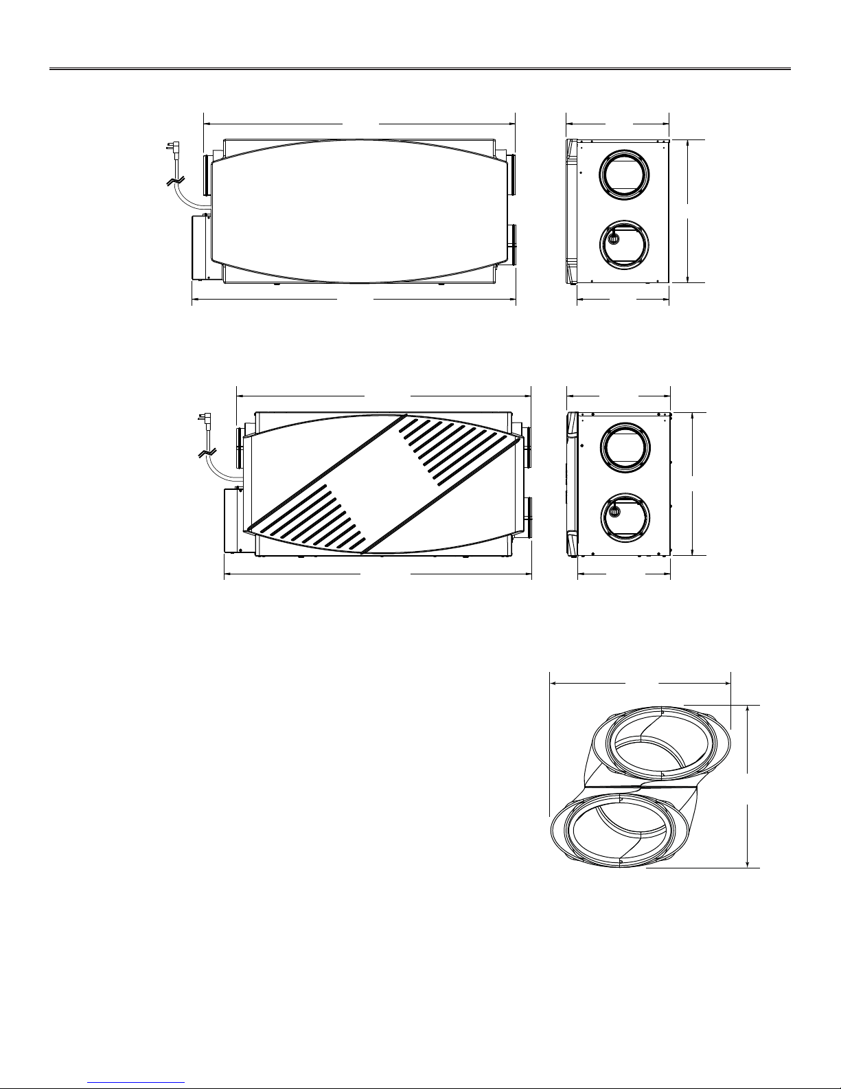
2. DIMENSIONS
2.1 EVO5 700 HRV HEPA AND HRV 7.1 HEPA UNITS
VK0082A
2.2 EVO5 500 HRV AND HRV 5.1 UNITS
37 7/8”
39 /8”
35 7/8”
12½”
11 ¼”
12½”
17 7/16”
7
/16”
17
VK0083A
2.3 JOIST OPENING REQUIRED FOR TANDEM® TRANSITION
The joist opening needed to install the Tandem tansition* (included in ISKV1000
and ISKB1000 installation kits) must be 9¾” (248 mm) minimum. Also, the
maximum height of the Tandem transition is 8¾” (222 mm). See Tandem transition
end view at right.
* Patended
37
7
/16”
VD0118A
11¼”
9¾”
248 mm
8¾”
222 mm
5

3. INSTALLATION
A
VD0313
3.1 INSPECT THE CONTENT OF THE BOX
NOTE: Before proceeding to the installation, check the content of the box. If items are missing or damaged, contact the
manufacturer. Remove all packaging material from the unit.
• Inspect the exterior of the unit for shipping damage. Ensure that there is no damage to the door, door latches, ports, power
cord, etc.
• Remove the transport bracket screws (A) located on the bottom of
the unit.
• Unlatch, open (B) and remove (C) the unit door.
CAUTION
In order to prevent damages to the door hooks, do not open completely
the unit door; tilt it about 3” from the unit base and lift it up. See
illustration at right.
• Remove the transport tape over the heat recovery core of the unit.
• Remove the last retaining screws (D) of the transport brackets
and discard.
VD0314
• Inspect the inside of the unit for damage. Ensure that blower
assembly, heat recovery core, core filters, insulation, dampers,
prefilter and HEPA filter (EVO5 700 HRV HEPA and HRV 7.1
HEPA units only), etc. are all intact, then reinstall the door.
NOTE: On EVO5 700 HRV HEPA and HRV 7.1 HEPA units only,
write the installation date on the HEPA filter frame for future
reference (see illustration at right).
C
VD0304A
±3”
B
D
TOP
DESSUS
FRONT
AVANT
Instal. date:
Date d’instal. :
__ / __ / ____
21293
FRONT
AVANT
Instal. date:
Date d’instal. :
__ / __ / ____
6
VD0309
3. INSTALLATION
3.2 INSTALLATION KITS, TOOLS AND MATERIAL
The installation kit needed to perform most installations is IKSV1000 for Venmar units and IKSB1000 for Broan units.
Following are the tools and material needed:
• Measuring tape
• Phillips no. 2 or Robertson no. 2 screwdriver
• Small flat blade screwdriver (for wall control connection)
• Wire stripper (for wall control connection)
• Hammer and flat blade screwdriver (for plenum connection installation only, to make holes in existing metal duct)
• Scissors or utility knife (to cut duct tape)
• Duct tape
• Tin snips or metal shear (for plenum connection installation only, to cut ductwork)
• Aluminum duct tape (for plenum connection installation only)
• Jig saw
• Caulking gun and caulking.
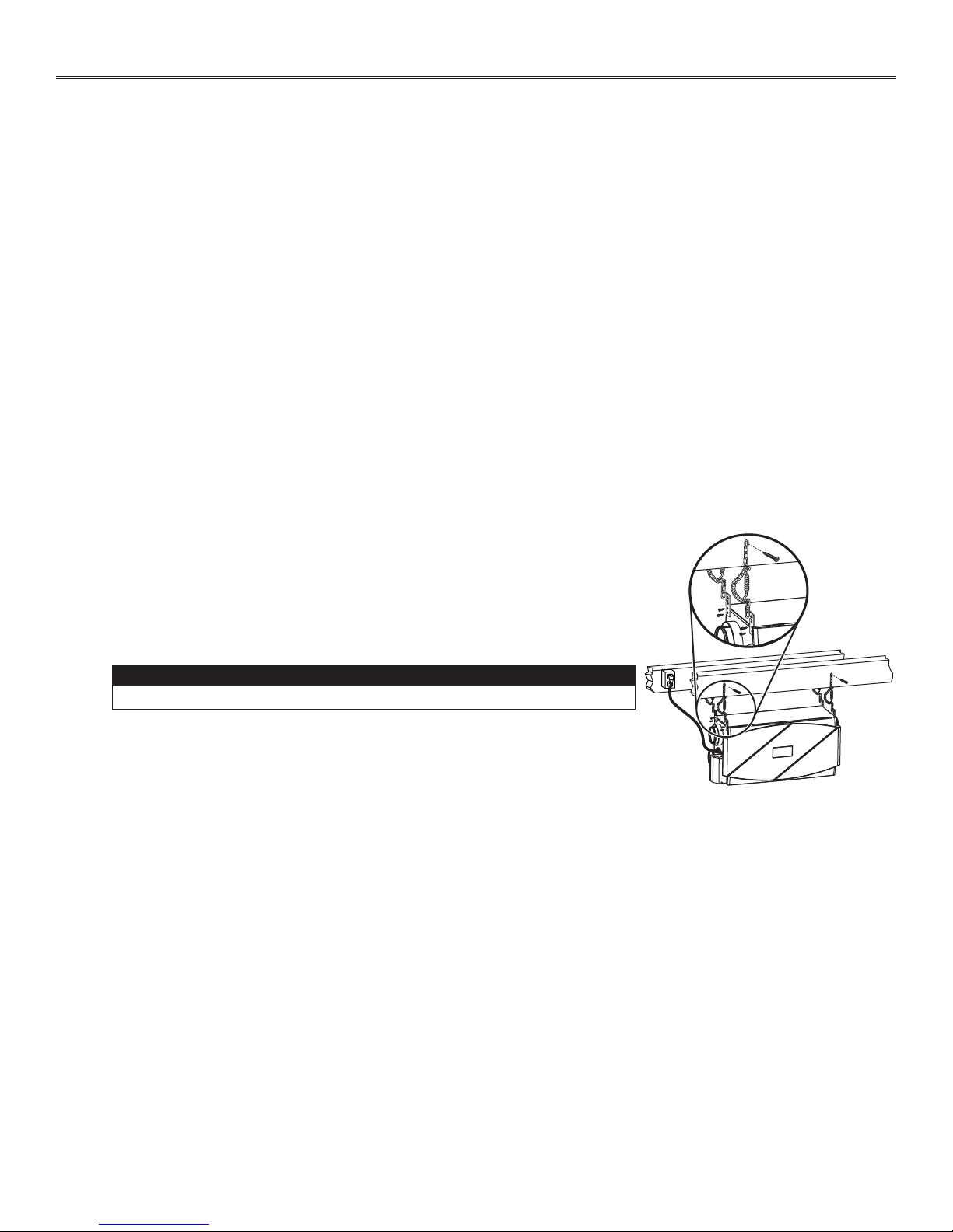
3.3 LOCATING THE UNIT
Choose an appropriate location for the unit.
• Within an area of the house where the ambient temperature is kept between 10°C (50°F) and 40°C (104°F)
• Away from living areas (dining room, living room, bedroom), if possible
• So as to provide easy access to the interior of the unit, for regular and annual maintenance
• Close to an exterior wall, so as to limit the length of the insulated flexible duct to and from the unit
• Away from hot chimneys and other fire hazards
• Allow for a power source (standard 3-prong grounding outlet)
• Close to a drain. If no drain is close by, use a pail to collect run-off.
Hang the unit with the four hooks, chains and springs provided. See illustration at right.
Make sure the unit is level.
3.4 PLANNING OF THE DUCTWORK
• Keep it simple. Plan for a minimum of bends and joints.
• Keep the length of insulated ducts to a minimum.
• Do not ventilate crawl spaces or cold rooms. Do not attempt to recover the exhaust air from a dryer or a range hood. This
would cause clogging of the filters and recovery module.
• If the house has two floors or more, be sure to plan for at least one exhaust register on the highest lived-in level.
CAUTION
VD0306
7
3. INSTALLATION (CONT’D)
3.5 INSTALLING NON-INSULATED DUCTS AND DIFFUSERS
3.5.1 FULLY DUCTED SYSTEM (AS ILLUSTRATED IN SECTION 1.1)
Never install a stale air exhaust diffuser in a closed room where a combustion device operates, such as a
gas furnace, a gas water heater or a fireplace.
Stale air exhaust ductwork
• Install the stale air exhaust diffuser in the main area where the contaminants are produced: kitchen, living room, etc. Position
the diffuser as far from the stairway as possible and in such a way that the air circulates in all the lived-in spaces in the house.
If desired, you can install another diffuser (sold separately).
• If a diffuser is installed in the kitchen, it must be located at least 4 feet (1.2 m) from the range.
• Install the diffuser 6 to 12 inches (152 to 305 mm) from the ceiling on an interior wall OR install it in the ceiling.
Fresh air distribution ductwork
• Install the fresh air distribution diffuser in a large, open area in the lowest level to ensure the greatest possible air circulation.
• Keep in mind that the fresh air diffuser must be located as far as possible from the stale air diffuser. If desired, you can install
another diffuser (sold separately).
• Install the diffuser either in the ceiling OR 6 to 12 inches (152 to 305 mm) from the ceiling on an interior wall. (The cooler air
will then cross the upper part of the room and mix with room air, before descending to occupant’s level.)
• If a register must be floor installed, direct the airflow up the wall.
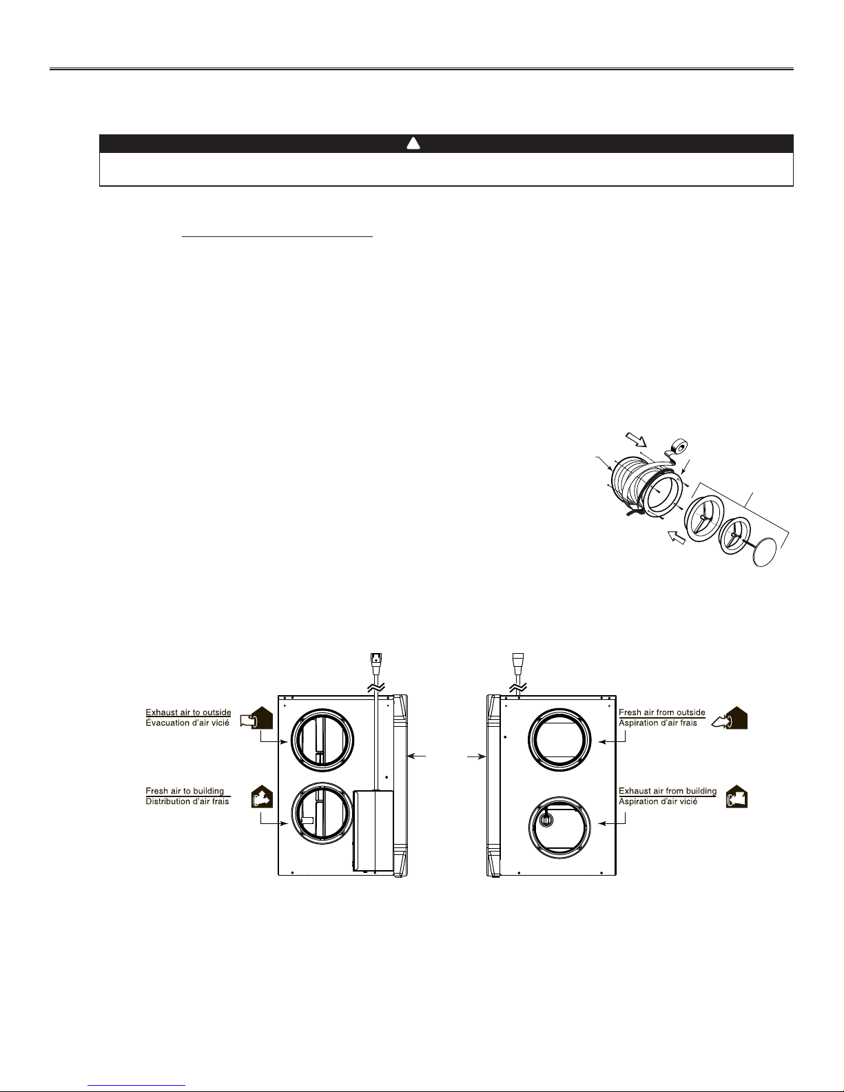
HOW TO CONNECT THE FLEXIBLE DUCTS TO THE DIFFUSERS
!
WARNING
Ø 5¼”
1
Once the diffusers location is determined, cut out 5¼” diameter hole.
Run one end of the flexible duct through the hole and fix it to the diffuser base (1),
using a tie wrap and duct tape. Assemble the diffuser base to the wall (or ceiling
2
using its 4 no. 8 x 3/4” screws. Then, slide in the diffuser (2).
See illustration at right.
VJ0094A
UNIT PORTS IDENTIFICATION
Each unit port has an identification label beside it to avoid wrong duct connections to the unit. Always refer to these labels before
performing any duct and port connection.
UNIT
DOOR
VJ0096
8
 Loading...