

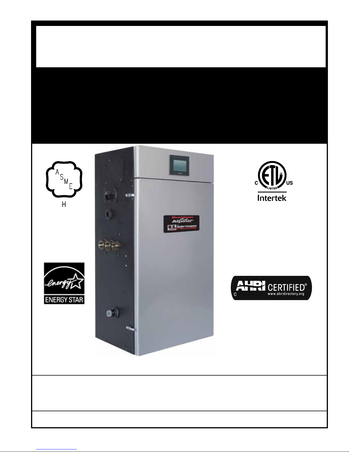
Energy Star ALPINE, ALP080B, ALP105B, ALP150B, ALP210B Installation, Operating And Service Instructions
...Page 1
DNAGNITAREPO,NOITALLATSNI
ROFSNOITCURTSNIECIVRES
™ENIPLA
YCNEICIFFEHGIHGNISNEDNOC
TNEVTCERID
RELIOBRETAWTOHDERIF-SAG
9700609
As an ENERGY STAR
STAR® guidelines for energy efciency established by the United States Environmental Protection Agency (EPA).
WARNING: Improper installation, adjustment, alteration, service or maintenance can cause property damage,
injury, or loss of life. For assistance or additional information, consult a qualied installer, service agency or the
gas supplier. This boiler requires a special venting system. Read these instructions carefully before installing.
103448-02 - 6/13 Price - $5.00
®
Partner, U.S. Boiler Company has determined that the Alpine™ Series meets the ENERGY
Page 2
IMPORTANT INFORMATION - READ CAREFULLY
NOTE: The equipment shall be installed in accordance with those installation regulations enforced in the area where the
installation is to be made. These regulations shall be carefully followed in all cases. Authorities having jurisdiction
shall be consulted before installations are made.
All wiring on boilers installed in the USA shall be made in accordance with the National Electrical Code and/or local regulations.
All wiring on boilers installed in Canada shall be made in accordance with the Canadian Electrical Code and/or local regulations.
The City of New York requires a Licensed Master Plumber supervise the installation of this product.
The Massachusetts Board of Plumbers and Gas Fitters has approved the Alpine™ Series boiler. See the Massachusetts Board of
Plumbers and Gas Fitters website, http://license.reg.state.ma.us/pubLic/pl_products/pb_pre_form.asp for the latest Approval
Code or ask your local Sales Representative.
The Commonwealth of Massachusetts requires this product to be installed by a Licensed Plumber or Gas Fitter.
The following terms are used throughout this manual to bring attention to the presence of hazards of various risk levels, or to
important information concerning product life.
DANGER
Indicates an imminently hazardous situation
which, if not avoided, will result in death, serious
injury or substantial property damage.
WARNING
Indicates a potentially hazardous situation which,
if not avoided, could result in death, serious injury
or substantial property damage.
Indicates a potentially hazardous situation which,
if not avoided, may result in moderate or minor
injury or property damage.
Indicates special instructions on installation,
operation, or maintenance which are important
but not related to personal injury hazards.
CAUTION
NOTICE
DANGER
DO NOT store or use gasoline or other ammable vapors or liquids in the vicinity of this or any other
appliance.
If you smell gas vapors, NO NOT try to operate any appliance - DO NOT touch any electrical switch or use
any phone in the building. Immediately, call the gas supplier from a remotely located phone. Follow the gas
supplier’s instructions or if the supplier is unavailable, contact the re department.
2 103448-02 - 6/13
Page 3

Special Installation Requirements for Massachusetts
A. For all sidewall horizontally vented gas fueled equipment installed in every dwelling, building or structure used in whole or
in part for residential purposes and where the sidewall exhaust vent termination is less than seven (7) feet above grade, the
following requirements shall be satised:
1. If there is no carbon monoxide detector with an alarm already installed in compliance with the most current edition of
NFPA 720, NFPA 70 and the Massachusetts State Building Code in the residential unit served by the sidewall horizontally
vented gas fueled equipment, a battery operated carbon monoxide detector with an alarm shall be installed in compliance
with the most current edition of NFPA 720, NFPA 70 and the Massachusetts State Building Code.
2. In addition to the above requirements, if there is not one already present, a carbon monoxide detector with an alarm
and a battery back-up shall be installed and located in accordance with the installation requirements supplied with the
detector on the oor level where the gas equipment is installed. The carbon monoxide detector with an alarm shall
comply with 527 CMR, ANSI/UL 2034 Standards or CSA 6.19 and the most current edition of NFPA 720. In the event
that the requirements of this subdivision can not be met at the time of the completion of the installation of the equipment,
the installer shall have a period of thirty (30) days to comply with this requirement; provided, however, that during
said thirty (30) day period, a battery operated carbon monoxide detector with an alarm shall be installed in compliance
with the most current edition of NFPA 720, NFPA 70 and the Massachusetts State Building Code. In the event that the
sidewall horizontally vented gas fueled equipment is installed in a crawl space or an attic, the carbon monoxide detector
may be installed on the next adjacent habitable oor level. Such detector may be a battery operated carbon monoxide
detector with an alarm and shall be installed in compliance with the most current edition of NFPA 720, NFPA 70 and the
Massachusetts State Building Code.
3. A metal or plastic identication plate shall be permanently mounted to the exterior of the building at a minimum height
of eight (8) feet above grade directly in line with the exhaust vent terminal for the horizontally vented gas fueled
heating appliance or equipment. The sign shall read, in print size no less than one-half (1/2) inch in size, “GAS VENT
DIRECTLY BELOW. KEEP CLEAR OF ALL OBSTRUCTIONS”.
4. A nal inspection by the state or local gas inspector of the sidewall horizontally vented equipment shall not be performed
until proof is provided that the state or local electrical inspector having jurisdiction has granted a permit for installation of
carbon monoxide detectors and alarms as required above.
B. EXEMPTIONS: The following equipment is exempt from 248 CMR 5.08(2)(a) 1 through 4:
1. The equipment listed in Chapter 10 entitled “Equipment Not Required To Be Vented” in the most current edition of NFPA
54 as adopted by the Board; and
2. Product Approved sidewall horizontally vented gas fueled equipment installed in a room or structure separate from the
dwelling, building or structure used in whole or in part for residential purposes.
C. When the manufacturer of Product Approved sidewall horizontally vented gas equipment provides a venting system design
or venting system components with the equipment, the instructions for installation of the equipment and the venting system
shall include:
1. A complete parts list for the venting system design or venting system; and
2. Detailed instructions for the installation of the venting system design or the venting system components.
D. When the manufacturer of a Product Approved sidewall horizontally vented gas fueled equipment does not provide the parts
for venting ue gases, but identies “special venting systems”, the following shall be satised:
1. The referenced “special venting system” instructions shall be included with the appliance or equipment installation
instructions; and
2. The “special venting systems” shall be Product Approved by the Board, and the instructions for that system shall include a
parts list and detailed installation instructions.
E. A copy of all installation instructions for all Product Approved sidewall horizontally vented gas fueled equipment, all venting
instructions, all parts lists for venting instructions, and/or all venting design instructions shall remain with the appliance or
equipment at the completion of the installation.
103448-02 - 6/13 3
Page 4
WARNING
This boiler requires regular maintenance and service to operate safely. Follow the instructions contained
in this manual.
Improper installation, adjustment, alteration, service or maintenance can cause property damage, personal
injury or loss of life. Read and understand the entire manual before attempting installation, start-up
operation, or service. Installation and service must be performed only by an experienced, skilled, and
knowledgeable installer or service agency
This boiler must be properly vented.
This boiler needs fresh air for safe operation and must be installed so there are provisions for adequate
combustion and ventilation air.
The interior of the venting system must be inspected and cleaned before the start of the heating season
and should be inspected periodically throughout the heating season for any obstructions. A clean and
unobstructed venting system is necessary to allow noxious fumes that could cause injury or loss of life
to vent safely and will contribute toward maintaining the boiler’s efciency.
Installation is not complete unless a safety relief valve is installed into the tapping located on left side of
boiler. - See the Water Piping and Trim Section of this manual for details.
This boiler is supplied with safety devices which may cause the boiler to shut down and not re-start
without service. If damage due to frozen pipes is a possibility, the heating system should not be left
unattended in cold weather; or appropriate safeguards and alarms should be installed on the heating
system to prevent damage if the boiler is inoperative.
This boiler contains very hot water under pressure. Do not unscrew any pipe ttings nor attempt to disconnect any components of this boiler without positively assuring the water is cool and has no pressure.
Always wear protective clothing and equipment when installing, starting up or servicing this boiler to
prevent scald injuries. Do not rely on the pressure and temperature gauges to determine the temperature
and pressure of the boiler. This boiler contains components which become very hot when the boiler is
operating. Do not touch any components unless they are cool.
Boiler materials of construction, products of combustion and the fuel contain alumina, silica, heavy metals,
carbon monoxide, nitrogen oxides, aldehydes and/or other toxic or harmful substances which can cause
death or serious injury and which are known to the state of California to cause cancer, birth defects and
other reproductive harm. Always use proper safety clothing, respirators and equipment when servicing
or working nearby the boiler.
Failure to follow all instructions in the proper order can cause personal injury or death. Read all instructions, including all those contained in component manufacturers manuals which are provided with the
boiler before installing, starting up, operating, maintaining or servicing.
All cover plates, enclosures and guards must be in place at all times.
NOTICE
This boiler has a limited warranty, a copy of which is included with this boiler. It is the responsibility of
the installing contractor to see that all controls are correctly installed and are operating properly when the
installation is complete.
4 103448-02 - 6/13
Page 5
TABLE OF CONTENTS
I. Product Description, Specications and Dimensional Data...................... 6
II. Unpacking Boiler........................................................................................ 11
III. Pre-Installation and Boiler Mounting ........................................................ 12
IV. Venting...................................................................................................... 19
A. General Guidelines............................................................................... 19
B. CPVC/PVC Venting.............................................................................. 22
C. Polypropylene Venting......................................................................... 31
D. Stainless Steel Venting........................................................................ 37
E. Concentric Polypropylene Venting....................................................... 39
F. Removing the Existing Boiler............................................................... 44
G. Multiple Boiler Installation Venting....................................................... 46
V. Condensate Disposal................................................................................. 50
VI. Water Piping and Trim............................................................................... 52
VII. Gas Piping ............................................................................................... 67
VIII. Electrical ................................................................................................... 71
IX. System Start-up ....................................................................................... 83
X. Operation...................................................................................................... 91
A. Overview............................................................................................... 91
B. Supply Water Temperature Regulation................................................ 92
C. Boiler Protection Features.................................................................... 93
D. Multiple Boiler Control Sequencer........................................................ 94
E. Boiler Sequence of Operation.............................................................. 95
1. Normal Operation........................................................................... 95
2. Using The Display.......................................................................... 96
F. Viewing Boiler Status............................................................................ 97
1. Status Screens.............................................................................. 97
2. Detail Screens............................................................................... 98
3. Multiple Boiler Sequencer Screens................................................ 99
G. Changing Adjustable Parameters........................................................ 100
1. Entering Adjust Mode.................................................................... 100
2. Adjusting Parameters..................................................................... 100
XI. Service and Maintenance ........................................................................ 111
XII. Troubleshooting........................................................................................ 115
XIII. Repair Parts ............................................................................................. 119
Appendix A - Figures................................................................................ 131
Appendix B - Tables.................................................................................. 134
103448-02 - 6/13 5
Page 6

I. Product Description, Specications and Dimensional Data
Alpine™ Series boilers are condensing high efciency
gas-red direct vent hot water heating boilers designed
for use in forced hot water space or space heating with
indirect domestic hot water heating systems, where supply
water temperature does not exceed 210°F. These boilers
have special coil type stainless steel heat exchangers,
constructed, tested and stamped per Section IV ‘Rules
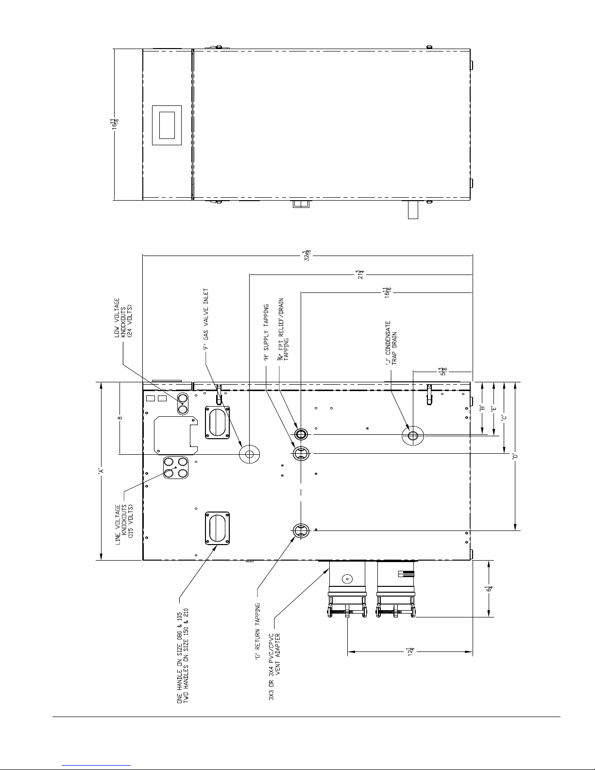
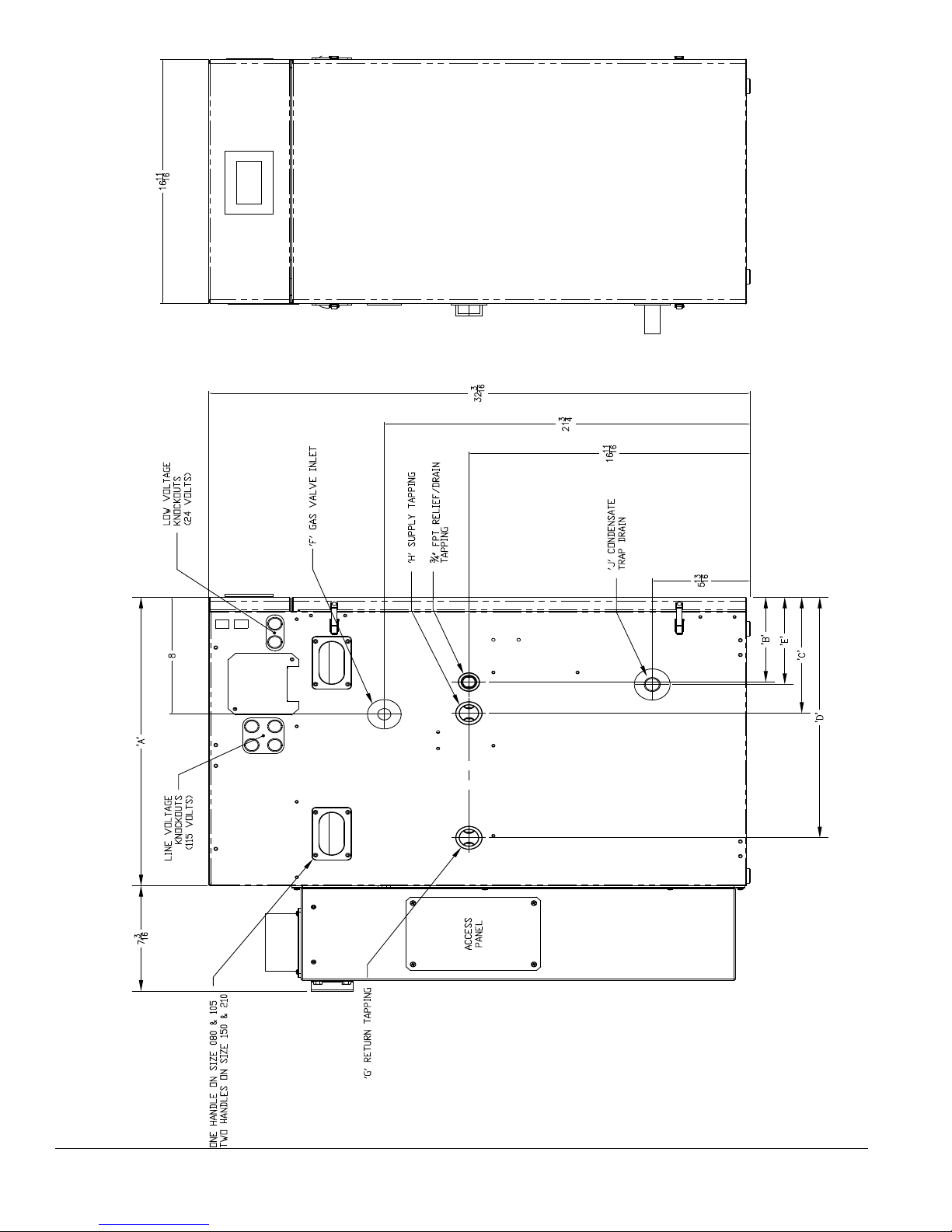
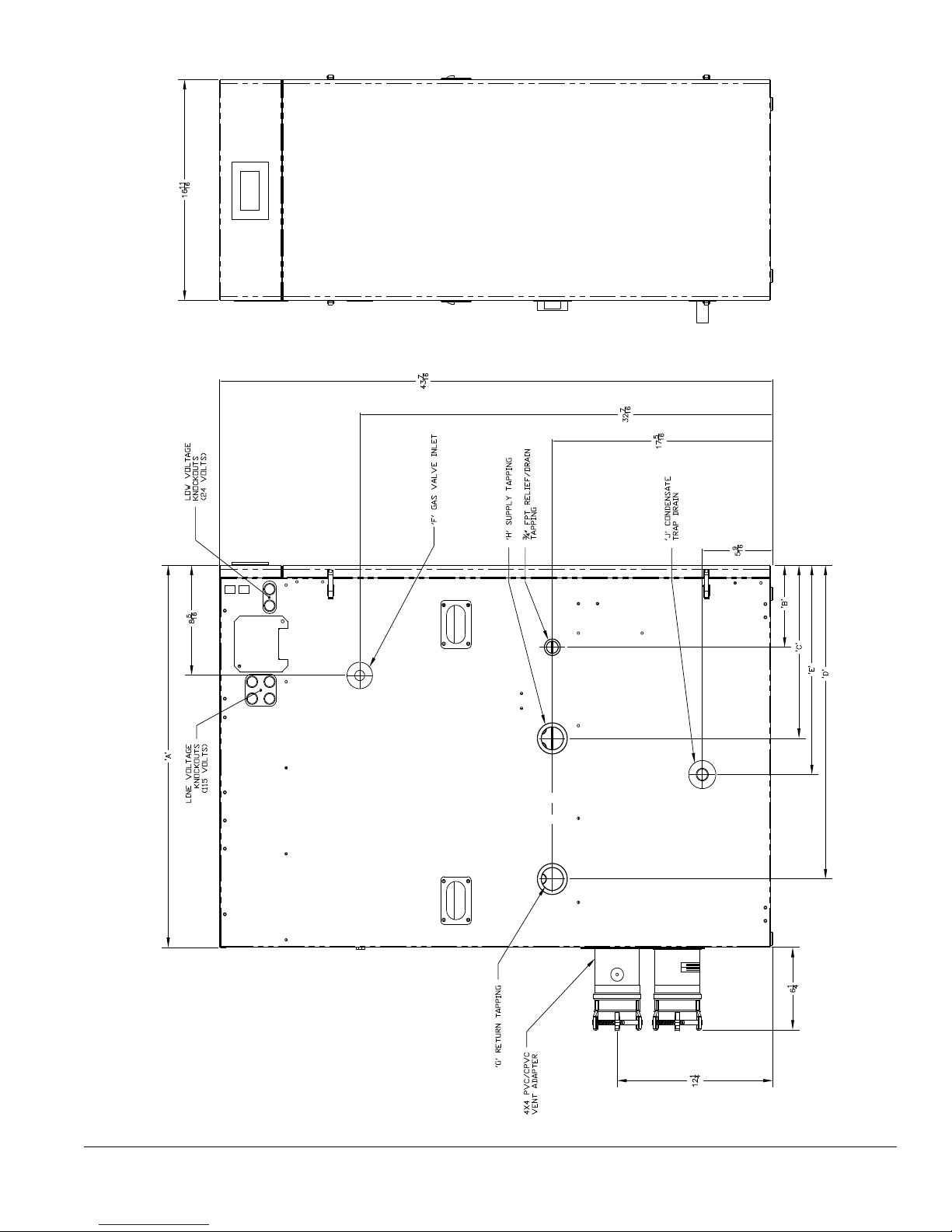
Table 1: Dimensional Data (See Figures 1A, 1B, & 1C)
Dimension
A - Inch
(mm)
B - Inch
(mm)
C - Inch
(mm)
D - Inch
(mm)
E - Inch
(mm)
Gas Inlet F
(FPT)
Return G
(FPT)
Supply H
(FPT)
Condensate Drain J *
Boiler Two-Pipe
CPVC/PVC Vent Connector
(Figs. 1A, 1C) - Inch
Boiler
CPVC Vent Connector/Pipe
(Fig. 1B) - Inch
Boiler Inlet Air Connector
(Fig. 1B) - Inch
Approx. Shipping Weight
(LBS)
ALP080B
12-9/16
9-5/16
(1)
ALP105B
14
(320)
(356)
5-5/8
(142)
10-3/4
(237)
(273)
* Factory Provided Socket End Compression Pipe Joining Clamp
3 x 3 3 x 4 4 x 4
3” 3” 4” 4” N/A N/A
137 155 182 206 256 304
for Construction of Heating Boilers’ of ASME Boiler and
Pressure Vessel Code, which provide a maximum heat
transfer and simultaneous protection against ue gas product
corrosion. These boilers are not designed for use in gravity
hot water space heating systems or systems containing
signicant amount of dissolved oxygen (swimming pool
water heating, direct domestic hot water heating, etc.).
Boiler Model
(1)
ALP150B
19-11/16
5-13/16
7-5/16
(186)
16-7/16
5-15/16
(151)
1/2” 3/4” 3/4”
1” 1-1/4” 1-1/2”
1” 1-1/4” 1-1/2”
for 3/4” Schedule 40 PVC Pipe
3” N/A N/A
(500)
(147)
(417)
(1)
ALP210B
23-15/16
(608)
17-1/8
(435)
(1)
ALP285B
21-13/16
(554)
7-5/16
(185)
14-1/8
(358)
18
(456)
12-1/4
(312)
(2)
ALP399
15-13/16
(2)
28-7/8
(734)
6-3/16
(157)
13-1/16
(332)
23-3/4
(602)
(402)
NOTES:
(1)
- These boiler models available as either Floor mounted (sufx F) or, Wall mounted (sufx W).
(2)
- These boiler models available as Floor mounted (sufx F) only.
6 103448-02 - 6/13
Page 7
I. Product Description, Specications and Dimensional Data (continued)
103448-02 - 6/13 7
Figure 1A: Alpine™ - Models ALP080B thru ALP210B (Floor Mounted)
Page 8
I. Product Description, Specications and Dimensional Data (continued)
8 103448-02 - 6/13
Figure 1B: Alpine™ - Models ALP080B thru ALP210B (Wall Mounted)
Page 9
I. Product Description, Specications and Dimensional Data (continued)
103448-02 - 6/13 9
Figure 1C: Alpine™ - Models ALP285B thru ALP399 (Floor Mounted Only)
Page 10

I. Product Description, Specications and Dimensional Data (continued)
Table 2A: Rating Data - Models ALP080B thru ALP399 (0 to 2000 Feet Elevation Above Sea Level)
Alpine Series Gas-Fired Boilers
* Model Number
ALP080B 16 80 0.6 7.3
ALP105B 21 105 0.7 9.1
ALP150B 30 150 1.3 16.4
ALP210B 42 210 1.7 21.8
ALP285B 57 285 2.4 29.1
ALP399 80 399 3.4 41.8
* Add Sufx “F” for Floor mounted Models or Sufx “W” for Wall mounted Models.
Notes: Maximum Working Pressure, Water - 30 PSI Shipped from Factory (std.); 50 PSI, 80 PSI
and 100 PSI - Optional (ALP080B thru ALP285B)
Maximum Working Pressure, Water - 50 PSI Shipped from Factory (std.); 80 PSI and 100
PSI - Optional (ALP399 only)
Maximum Allowable Temperature, Water - 210°F, Maximum Firing Rate
Target Setpoint is 190°F, Automatic Reset High Limit Setpoint is 200°F and Manual Reset
High Limit Setpoint is 210°F.
Boilers are factory shipped as Natural Gas builds and have to be eld adjusted for LP gas
application. Refer to ‘System Start-Up Section of the Installation, Operating and Service
Instructions manual for detailed procedure.
Ratings shown are for installations at sea level and elevations up to 2000 Feet. For
elevations above 2000 Feet, ratings should be reduced at the rate of four percent (4%) for
each 1000 Feet above sea level.
Input (MBH)
Min. Max.
Boiler Water
Volume (Gal.)
Heat Transfer Area
(Sq. Ft.)
Table 2B: Rating Data - Models ALP080B thru ALP399 (2001 to 7000 Feet Elevation Above Sea Level)
Alpine Series Gas-Fired Boilers
Model Number *
ALP080B 27 80 0.6 7.3
ALP105B 35 105 0.7 9.1
ALP150B 50 150 1.3 16.4
ALP210B 70 210 1.7 21.8
ALP285B 57 285 2.4 29.1
ALP399 80 399 3.4 41.8
* Add Sufx “F” for Floor mounted Models or Sufx “W” for Wall mounted Models.
Notes: Maximum Working Pressure, Water - 30 PSI Shipped from Factory (std.); 50 PSI, 80 PSI
and 100 PSI - Optional
Maximum Working Pressure, Water - 50 PSI Shipped from Factory (std.); 80 PSI and 100
PSI - Optional (ALP399 only)
Maximum Allowable Temperature, Water - 210°F, Maximum Firing Rate
Target Setpoint is 190°F, Automatic Reset High Limit Setpoint is 200°F and Manual Reset
High Limit Setpoint is 210°F.
Boilers are factory shipped as Natural Gas builds and have to be eld
adjusted for LP gas application. Refer to ‘System Start-Up” Section of the
Installation, Operating and Service Instructions manual for detailed
procedure.
For elevations above 2000 Feet, ratings should be reduced at the rate of four percent (4%)
for each 1000 Feet above sea level.
Input (MBH)
Min. Max.
Boiler Water
Volume (Gal.)
Heat Transfer Area
(Sq. Ft.)
10 103448-02 - 6/13
Page 11
I. Product Description, Specications and Dimensional Data (continued)
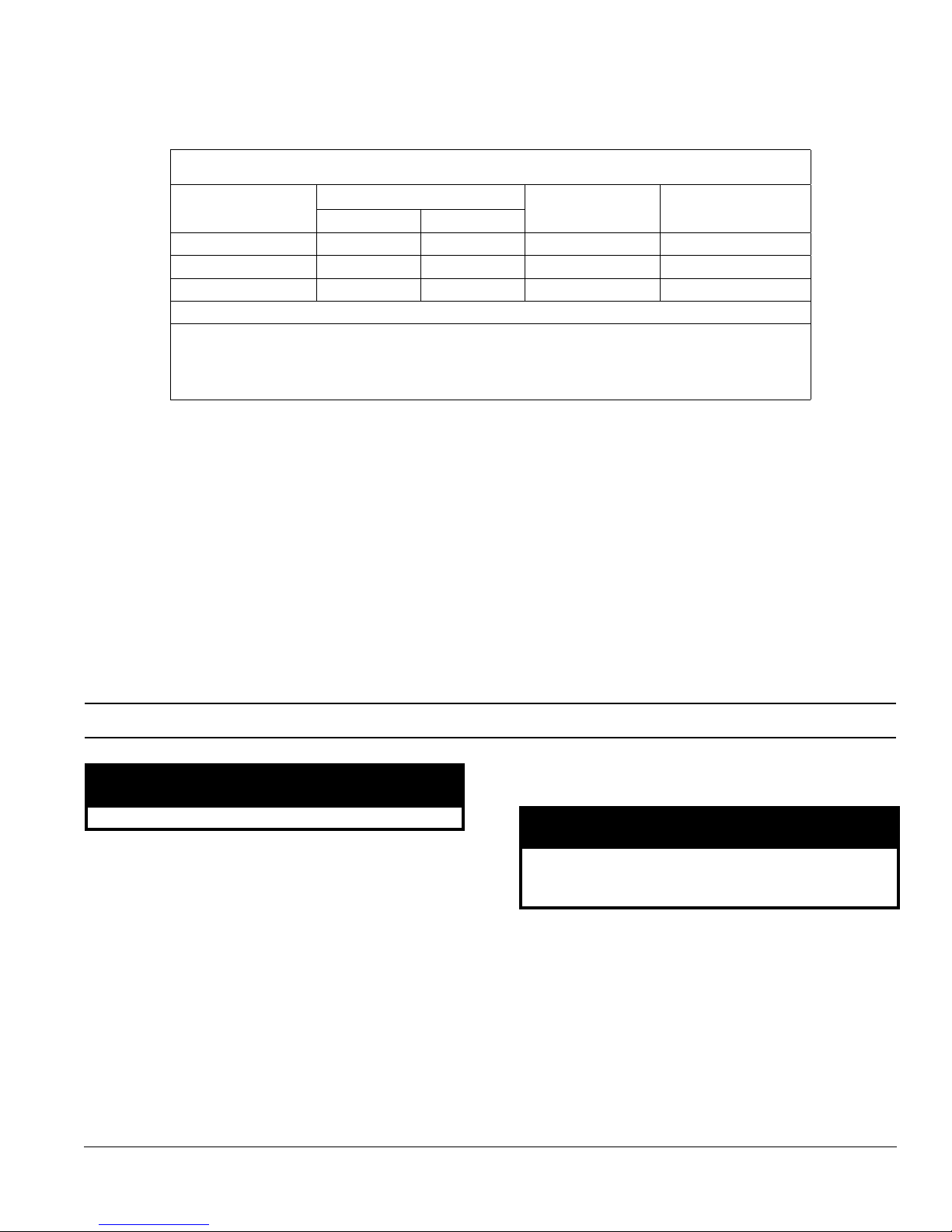
Table 2C: Rating Data - Models ALP150B thru ALP285B (7001 to 10,000 Feet Elevation Above Sea Level)
Alpine Series Gas-Fired Boilers
Model Number *
ALP150B 38 113 1.3 16.4
ALP210B 53 158 1.7 21.8
ALP285B 68 204 2.4 29.1
* Add Sufx “F” for Floor mounted Models or Sufx “W” for Wall mounted Models.
Notes: Maximum Working Pressure, Water - 30 PSI Shipped from Factory (std.); 50 PSI - Optional
Maximum Allowable Temperature, Water - 210°F
Boilers are factory shipped as Natural Gas builds only.
Input has been de rated for noted elevation above sea level.
More detailed boiler ratings can be found at U.S. Boiler’s web site (www.usboiler.net)
Input (MBH)
Min. Max.
Boiler Water
Volume (Gal.)
Heat Transfer Area
(Sq. Ft.)
II. Unpacking Boiler
CAUTION
Do not drop boiler.
A. Move boiler to approximate installed position.
B. Remove all crate fasteners.
C. Lift and remove outside container.
103448-02 - 6/13 11
D. Remove boiler from cardboard positioning sleeve on
shipping skid.
WARNING
Installation of this boiler should be undertaken
only by trained and skilled personnel from a
qualied service agency.
E. Move boiler to its permanent location.
Page 12
III. Pre-Installation and Boiler Mounting
WARNING
If you do not follow these instructions exactly,
a re or explosion may result causing property
damage or personal injury.
NOTICE
Due to the low water content of the boiler, missizing of the boiler with regard to the heating
system load will result in excessive boiler cycling
and accelerated component failure. U.S. Boiler
Company DOES NOT warrant failures caused
by mis-sized boiler applications. DO NOT
oversize the boiler to the system. Multiple boiler
installations greatly reduce the likelihood of
boiler oversizing.
A. Installation must conform to the requirements of the
authority having jurisdiction. In the absence of such
requirements, installation must conform to the National
Fuel Gas Code, NFPA 54/ANSI Z223.1, and/or CAN/
CSA B149.1 Natural Gas and Propane Installation
Code.
B. Boiler is design certied for installation on
combustible ooring. Do not install boiler on
carpeting.
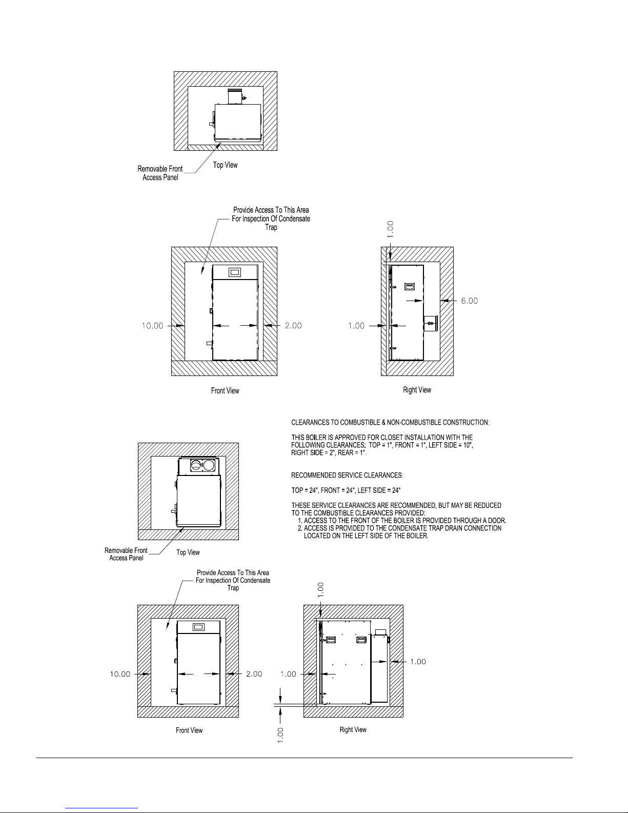
C. Provide clearance between boiler jacket and
combustible material in accordance with local re
ordinance. Refer to Figures 2A and 2B for minimum
listed clearances from combustible material.
Recommended service clearance is 24 inches from left
side, front, top and rear of the boiler. Recommended
front clearance may be reduced to the combustible
material clearance providing:
1. Access to boiler front is provided through a door or
removable front access panel.
2. Access is provided to the condensate trap located
underneath the heat exchanger.
D. Protect gas ignition system components from water
(dripping, spraying, rain, etc.) during boiler operation
and service (circulator replacement, condensate trap,
control replacement, etc.).
E. Provide combustion and ventilation air in accordance
with applicable provisions of local building codes,
or: USA - National Fuel Gas Code, NFPA 54/ANSI
Z223.1, Air for Combustion and Ventilation;
Canada - Natural Gas and Propane Installation Code,
CAN/CSA-B149.1, Venting Systems and Air Supply for
Appliances.
WARNING
Adequate combustion and ventilation air must
be provided to assure proper combustion.
F. The boiler should be located so as to minimize the
length of the vent system. The combustion air piping,
or the optional concentric vent piping, containing
integral combustion air inlet piping, must terminate
where outdoor air is available for combustion and
away from areas that may contaminate combustion
air. In particular, avoid areas near chemical products
containing chlorines, chlorouorocarbons, paint
removers, cleaning solvents and detergents. Avoid
areas containing saw dust, loose insulation bers, dry
wall dust etc.
CAUTION
Avoid operating this boiler in an environment
where saw dust, loose insulation bers, dry wall
dust, etc. are present. If boiler is operated under
these conditions, the burner interior and ports
must be cleaned and inspected daily to insure
proper operation.
G. General.
1. Alpine boilers are intended for installations in an
area with a oor drain or in a suitable drain pan to
prevent any leaks or relief valve discharge to cause
property damage
2. Alpine boilers are not intended to support external
piping and venting. All external piping and venting
must be supported independently of the boiler.
3. Alpine boilers must be installed level to prevent
condensate from backing up inside the boiler.
4. Alpine boilers can be installed either as oor
standing (ALP080B thru ALP399, or, as wall hung
(ALP080B thru ALP210B). Factory assembled
oor standing models are identied with sufx F in
a boiler part number code (example – ALP210BF1L02). Factory assembled wall hung models are
identied with sufx W in a boiler part number code
(example – ALP210BW-1L02).
5. Boiler Floor Standing Installation:
a. For basement installation provide a solid base
such as concrete, where oor is not level or water
may be encountered on the oor around boiler.
Floor must be able to support weight of boiler,
water and all additional system components.
b. Boiler must be level to prevent condensate from
backing up inside the boiler.
12 103448-02 - 6/13
Page 13
III. Pre-Installation and Boiler Mounting G. General (continued)
c. Provide adequate space for condensate piping or
a condensate pump if required.
6. Boiler Wall Hung Installation:
a. If the boiler is installed on a framed wall,
minimum acceptable framing is 2 x 4 studs on
16” centers. The boiler mounting holes are on
16” centers for installation between two studs
at the standard spacing. In cases where the
boiler cannot be centered between the studs, or
where the studs are spaced closer than 16” apart,
the boiler may be anchored to ¾” plywood or
horizontal 2 x 4’s anchored to the studs.
CAUTION
Alpine boiler approximate dry weights:
ALP080BW – 98 lbs; ALP105BW – 112 lbs;
ALP150BW – 136 lbs: ALP210BW – 150 lbs
Two people are required to safely lift these
boilers onto the installed wall mounting
bracket.
Make sure that wall mounting bracket is anchored to a structure capable of supporting
the weight of the boiler and attached piping
when lled with water. Jurisdictions in areas
subject to earthquakes may have special requirements for supporting these boilers. Such
local requirements take precedence over the
requirements shown below.
b. Locate Wall Mounting Bracket Kit carton (p/n
102988-01) enclosed inside boiler carton. The
kit contains Wall Mounting Bracket, Bottom
Securing Bracket, (4) 5/16” x 2” long hex head
lag screws, (4) 5/16” at plated washers and (2)
#8 x ½” Phillips round head sheet metal screws.
c. 5/16” x 2” lag screws and 5/16” plated washers
are intended for mounting the boiler directly onto
studs covered with ½” drywall. When the boiler
is attached to other types of construction, such
as masonry, use fasteners capable of supporting
the weight of the boiler and attached piping in
accordance with good construction practice and
applicable local codes.
d. Make sure that the surface to which the boiler is
mounted is plumb.
e. Before mounting the boiler, make sure that wall
selected does not have any framing or other
construction that will interfere with the vent pipe
penetration.
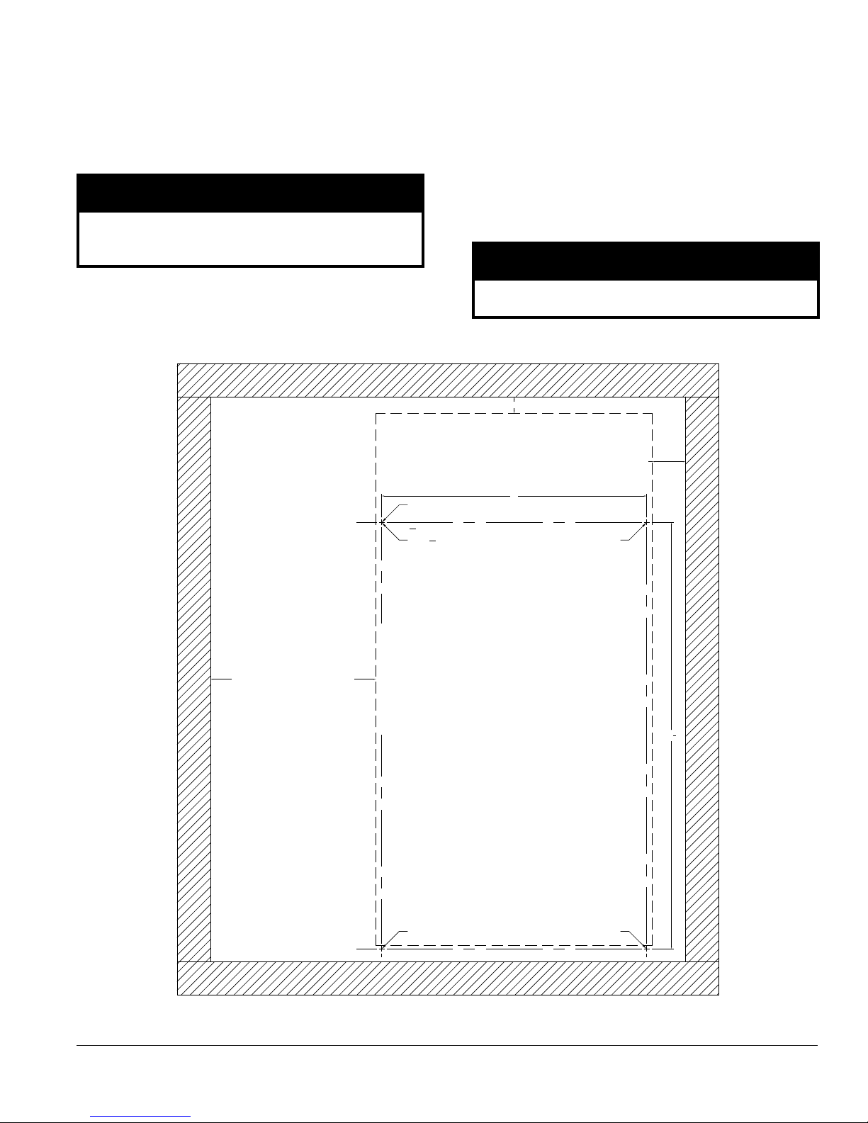
f. Once a suitable location has been selected for the
boiler, and any needed modications have been
made to the wall, use Figure 2C to locate and
layout holes “A” and “B”. These holes must be
positioned on mounting stud centers if the boiler
is installed on a framed wall. Make sure that
the horizontal centerline of these holes is level.
Holes “C” and “D” may also be drilled at this
time, or after the boiler is hung on the wall. If the
5/16 x 2” lag screws are used, drill 3/16” pilot
holes.
g. An alternate way to locate/mark holes “A” and
“B” is to use template P/N 102986-01 enclosed
into Vent Part Carton [P/N 102981-01
(ALP080BW/105BW) or P/N 102981-02
(ALP150BW/210W)], which can be found inside
boiler carton.
CAUTION
The outer edges of the template represent
minimum side, top and bottom clearances to
combustible material. If the template needs to be
cut to t into a selected location, it would indicate
the minimum clearances to combustible material
are not met.
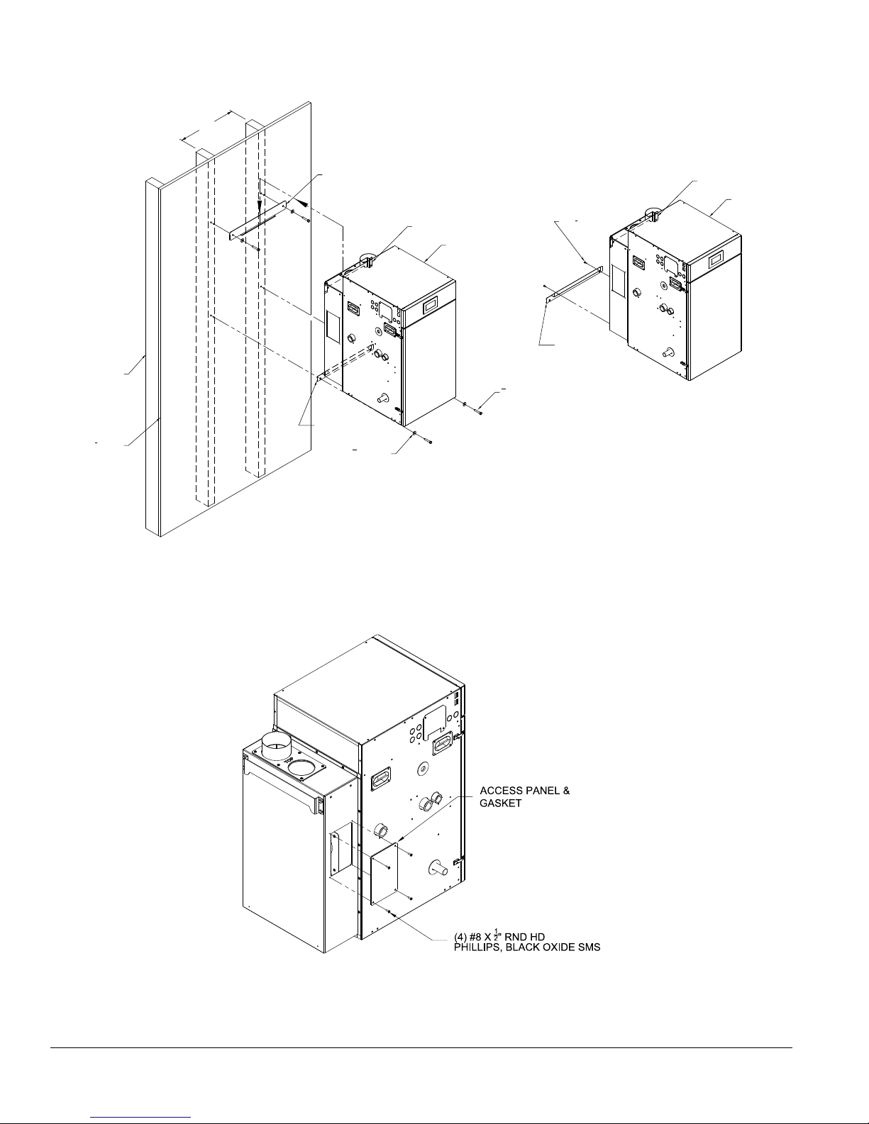
h. Attach the wall hanging bracket using the 5/16”
x 2” lag screws and 5/16” plated washers, or
other suitable anchors as appropriate (Figure
2D). Make sure the bracket is level.
i. Attach Bottom Securing Bracket to boiler air box
with two #8 x ½” Phillips round head sheet metal
screws. Refer to Figure 2D for details.
j. Hang the boiler on the installed wall bracket as
shown in Figure 2D.
k. If not already done in Step (4) locate and drill
holes “C” and “D” using the ob-round slots in
the Bottom Securing Bracket. Secure the Bracket
to the wall using the 5/16” x 2” lag screws
and 5/16” plated washers, or other fasteners as
appropriate (Figure 2D).
l. Verify that the front of the boiler is plumb. If it
is not, install shims (installer provided) at holes
“C” and “D” between the Bottom Securing
Bracket and the wall to adjust.
CAUTION
When positioning the template in the desired
location on the wall insure that the minimum
clearances to combustible material at
adjacent walls and ceiling are maintained. Consult
Figures 2A thru 2C in this manual. Be sure to
allow space at the boiler left side for gas and
water connections, as well as for access to the
condensate trap and boiler controls for servicing.
103448-02 - 6/13 13
Page 14
III. Pre-Installation and Boiler Mounting G. General (continued)
Figure 2A: Clearances To Combustible and Non-combustible Material, Floor Standing
Figure 2B: Clearances To Combustible and Non-combustible Material, Wall Mounted
14 103448-02 - 6/13
Page 15
III. Pre-Installation and Boiler Mounting G. General (continued)
m. See Section IV Venting; Paragraph B, 5 “Field
Installation of CPVC Vent Pipe - Wall Mounted
Boiler Builds” for instructions on attaching the
vent system to the boiler.
WARNING
Vent pipe must be inserted rmly into vent
connector and secured by tightening the metal
strap worm screw.
WALL MOUNTING BRACKET
CENTER LINE
1.0" MIN. CLEARANCE TO COMBUSTIBLE
TOP EDGE OF BOILER
'HOLE B'
3
16
" DIA. PILOT HOLES
5
16
FOR
" LAG SCREWS
(4 PLACES)
n. After the boiler has been piped, wired, connected
to vent and combustion air system piping and
combustion performance testing completed per
Section IX “System Start-up”, install Access
Panel/Gasket assembly and secure with provided
four #8 x ½” black oxide Phillips head sheet
metal screws. See Figure 2E “access Panel and
Gasket Installation”.
WARNING
Access Panel must be installed while boiler is in
operation.
2.0" MIN. CLEARANCE TO COMBUSTIBLE
16
'HOLE A'
10.0" MIN. CLEARANCE TO COMBUSTIBLES
BOTTOM SECURING
BRACKET CENTER LINE
LEFT SIDE OF BOILER
'HOLE C'
'HOLE D'
3
25
4
Figure 2C: Wall Mounting Hole Location / Layout
103448-02 - 6/13 15
Page 16
III. Pre-Installation and Boiler Mounting G. General (continued)
16" C/C
2 X 4
WALL STUD
1
2
" SHEET
ROCK
WALL BRACKET
1
2
#8 X
BOTTOM
SECURING
BRACKET
" SMS (2X)
BOTTOM
SECURING
BRACKET
5
16
" X 2" FLAT
WASHER (4X)
BOILER HANGING
BRACKET
BOILER
5
" X 2" LAG
16
SCREW (4X)
Figure 2D: Bottom Mounting Bracket Installation / Boiler Wall Mounting
BOILER HANGING
BRACKET
BOILER
Figure 2E: Access Panel and Gasket Installation
16 103448-02 - 6/13
Page 17
III. Pre-Installation and Boiler Mounting H. Boiler Stacking (continued)
H. Boiler Stacking
1. For installations with unusually high space heating
and/or domestic hot water heating loads, where
employing two (2) Alpine (ALP) boilers will offer
the benets of greater operational efciency, oor
space savings and boiler redundancy, the Alpine
(ALP) boilers may be installed stacked one on the
top of the other. Refer to Table 3 “Alpine (ALP)
Boiler Model Stacking Combinations” for details.
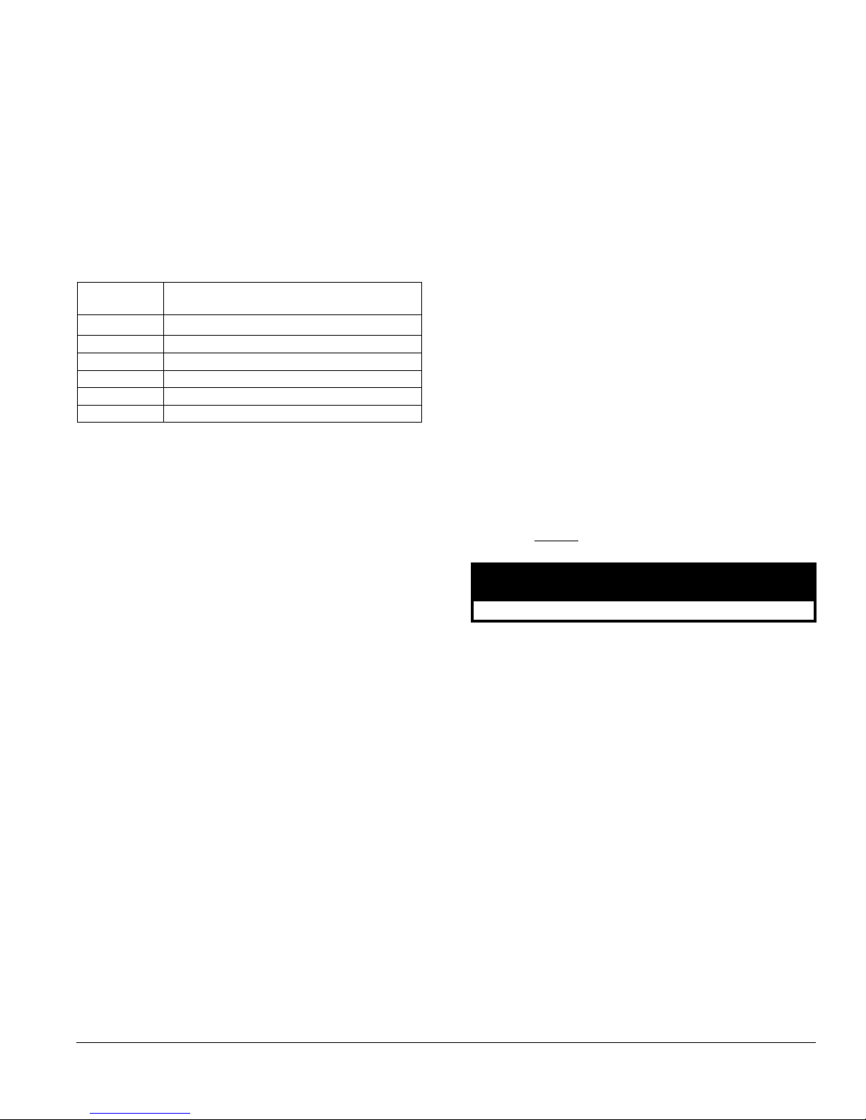
Table 3: Alpine (ALP) Boiler Model Stacking
Combinations
Bottom
Boiler Model
ALP080B
ALP105B
ALP150B
ALP210B
ALP285B ALP080B, ALP105B, ALP150B & ALP285B
ALP399 ALP080B thru ALP399
Notes:
(2)
(1)
(1)
(1)
(1)
(1)
Floor-mounted builds only
Floor-mounted or wall-mounted build where applicable
Top Boiler Model
ALP080B
ALP080B or ALP105B
ALP080B thru ALP150B
ALP080B thru ALP210B
2. To eld assemble individual Alpine (ALP) boilers
into a stackable conguration, use the steps below:
a. Position the bottom boiler rst. Refer to Sections
II “Unpacking Boiler” and III “Pre-Installation
& Boiler Mounting” of the manual for details.
Always position higher input boiler model as
bottom boiler.
b. Each Alpine (ALP) boiler is factory packaged
with two (2) Stacking Boiler Attachment
Brackets (P/N 101679-01) and the bracket
mounting hardware [six (6) self-drilling hex
washer head plated #8 x ½” long screws, P/N
80860743]. Locate and remove the brackets and
the hardware. The Stacking Boiler Attachments
Bracket has three 7/32” diameter holes punched
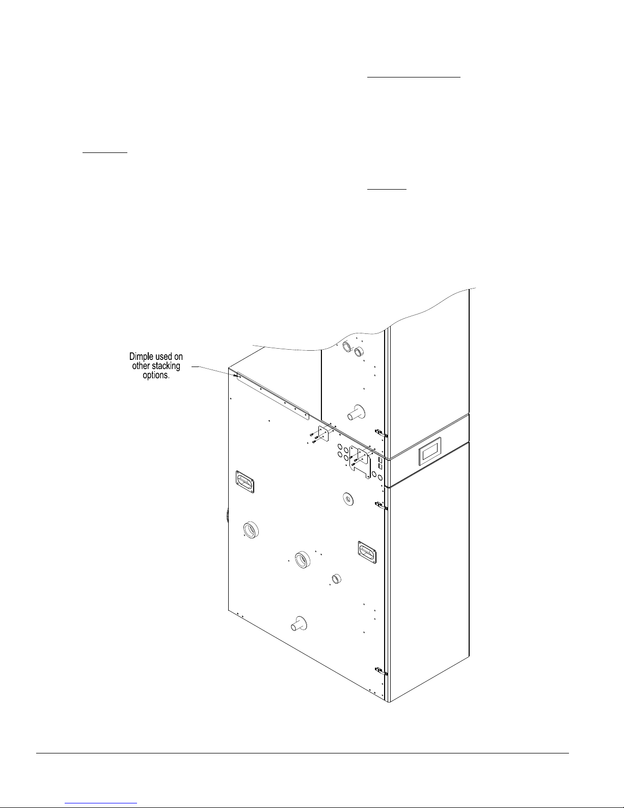
in a triangular pattern. See Figure 3 “Stacking
Boiler Attachment Bracket Placement”.
c. Alpine (ALP) boiler left and right side panels
have a series of dimples at panel top and bottom.
These dimples are positioning dimples for
Stacking Boiler Attachment Bracket mounting
screws. Side panel bottom positioning dimples
are evenly spaced from boiler front and back,
while side panel top positioning dimples follow
specic pattern to compensate for Alpine (ALP)
boiler model variable depth.
d. Position the upper boiler on the top of the bottom
boiler and align boiler front doors and sides ush
with each other.
• Place rst Stacking Boiler Attachment
Bracket onto the upper boiler left side panel,
at the panel lower left corner and align
(2)
bracket two upper holes with corresponding
side panel lower dimples.
• The remaining lower bracket hole must align
with a matching bottom boiler left side panel
top positioning dimple.
• Once bracket holes and side panel dimple
alignment is veried, attach the bracket to
top and bottom boiler left side panels with
the mounting screws.
e. Repeat above procedure to install second
Stacking Boiler Attachment Bracket and secure
the stacked boiler right side panels together at
the front right corner.
f. Install the third Stacking Boiler Attachment
Bracket to secure top and bottom boiler left side
panels at the rear left corner. Align the bracket
holes with corresponding positioning dimples in
the top boiler and bottom boiler left side panels,
then secure bracket with the screws.
g. Repeat above procedure to install the forth
Stacking Boiler Attachment Bracket to secure
stacked boiler right side panels at the rear right
corner.
3. When installing stackable boiler combinations
observe the following guidelines:
a. Venting - Top and bottom boilers must have their
individual vent piping and vent terminals.
WARNING
No common manifolded venting is permitted.
For side-wall venting individual model vent
terminals must terminate not closer than 12
inches horizontally and three (3) feet vertically
from each other in order to prevent combustion
air contamination. For vertical through the roof
venting, individual vertical vent terminals, if
level with each other, must be spaced no closer
than 12 inches horizontally. If vertical terminals
cannot end in one plane, they must be spaced no
closer than three (3) feet horizontally.
Chimney chase concentric venting is permitted
for modules, when stackable, providing
concentric vertical (roof) vent terminals, if level
with each other, are spaced no closer then 12
inches horizontally.
If vertical vent terminals cannot end in one
plane, they must be spaced no closer then three
(3) feet horizontally.
Follow instructions in Section IV “Venting”
of the manual for specics of individual boiler
vent termination. Follow instructions in Section
V “Condensate Disposal” for each individual
boiler ue gas condensate line construction and
103448-02 - 6/13 17
Page 18
III. Pre-Installation and Boiler Mounting H. Boiler Stacking (continued)
condensate disposal. Terminating individual
boiler condensate lines into common pipe prior
to drain disposal is permissible, providing
common pipe has sufcient ow capacity
to handle combined condensate volume of
stackable combination.
b. Gas Piping - Follow instructions in Section
VII “Gas Piping” of the manual for sizing
and installation of an individual boiler. When
common gas piping is sized, insure it will have
adequate capacity for combined input (CFH
gas ow) of the selected stackable boiler
combination.
c. Water Piping and Trim - Follow instructions
in Section VI “Water Piping and Trim” of the
manual for system piping and boiler secondary
piping selection/sizing based on combined
heating capacity and/or gross output of
the selected stackable boiler combination.
Follow instructions of Section VI “Water
Piping and Trim” for each individual boiler trim
installation.
d. Electrical - Follow instructions in Section VIII
“Electrical” of the manual to wire individual
boilers.
Figure 3: Stacking Boiler Attachment Bracket Placement
18 103448-02 - 6/13
Page 19
IV. Venting
WARNING
Failure to vent this boiler in accordance with these instructions could cause products of combustion to
enter the building resulting in severe property damage, personal injury or death.
Do not interchange vent systems or materials unless otherwise specied.
The use of thermal insulation covering vent pipe and ttings is prohibited.
Do not use a barometric damper, draft hood or vent damper with this boiler.
When using the CPVC/PVC vent option, the use of CPVC is required when venting in vertical or horizontal
chase ways.
The CPVC vent materials supplied with this boiler do not comply with B149.1.S1-07 and are not ap-
proved for use in Canadian jurisdictions that require vent systems be listed to ULC S636-2008. In
these jurisdictions, vent this boiler using either stainless steel Special Gas vent or a listed ULC S636
Class IIB venting system.
Do not locate vent termination where exposed to prevailing winds. Moisture and ice may form on
surface around vent termination. To prevent deterioration, surface must be in good repair (sealed,
painted, etc.).
Do not locate air intake vent termination where chlorines, chlorouorocarbons (CFC’s), petroleum
distillates, detergents, volatile vapors or other chemicals are present. Severe boiler corrosion and
failure will result.
The use of cellular core PVC (ASTM F891), cellular core CPVC or Radel (polyphenolsulfone) is prohibited.
Do not locate vent termination under a deck.
Do not reduce specied diameters of vent and combustion air piping.
When installing vent pipe through chimney, as a chase, no other appliance can be vented into the
chimney.
Do not allow low spots in the vent where condensate may pool.
A. General Guidelines
1. Vent system installation must be in accordance
with National Fuel Gas Code, NFPA 54/ANSI
Z221.3 or applicable provisions of local building
codes. Contact local building or re ofcials about
restrictions and installation inspection in your area.
2. The Alpine™ is designed to be installed as a
Direct Vent (sealed combustion) boiler. The air
for combustion is supplied directly to the burner
enclosure from outdoors and ue gases are vented
directly outdoors (through wall or roof).
3. The following combustion air/vent system options
are approved for use with the Alpine™ boilers (refer
to Table 4):
a. Two-Pipe CPVC/PVC Vent/Combustion Air
System - separate CPVC/PVC pipe serves to
expel products of combustion and separate PVC
pipe delivers fresh outdoor combustion air.
Refer to Part B for specic details.
b. Two-Pipe Polypropylene Vent/Combustion Air
System - separate rigid or exible polypropylene
pipe serves to expel products of combustion and
separate rigid polypropylene pipe or PVC pipe
delivers fresh outdoor combustion air. Refer to
part C for specic details.
103448-02 - 6/13 19
c. Two-Pipe Stainless Steel Vent/Combustion Air
System - separate stainless steel pipe serves to
expel products of combustion. Separate PVC or
galvanized pipe delivers fresh outdoor air. Refer
to Part C for specic details.
d. Concentric Inner Polypropylene Vent
and Outer Steel Combustion Air System
- the assembly consists of inner re resistant
polypropylene vent pipe and outer steel pipe
casing. The inner pipe serves as conduit to
expel products of combustion, while outdoor
fresh combustion air is drawn through the space
between the inner and outer pipes. Refer to Part
D for specic details.
4. Horizontal vent pipe must maintain a 1/4" per foot
slope down towards the boiler.
5. Horizontal combustion air pipe must maintain a
minimum ¼" per foot slope down towards terminal,
when possible. If not, slope toward boiler.
6. Do not install venting system components on
the exterior of the building except as specically
required by these instructions (refer to Figure 4):
a. Vent terminals must be at least 1 foot from door,
window, or gravity inlet into the building.
Page 20

IV. Venting A. General Guidelines (continued)
Table 4: Vent/Combustion Air System Options
Approved Direct
Vent System
Factory Standard
Two-Pipe,
CPVC/PVC
Vent and PVC
Air Intake
Available Optional
Two-Pipe, Rigid
Polypropylene
Vent (or Flexible
Polypropylene Liner
for Vertical venting
only) and Rigid
Polypropylene or PVC
Pipe Air Intake
Available Optional
Two-Pipe,
Stainless Steel Vent
and PVC/Galvanized
Steel Air Intake
Available Optional
Concentric, Inner
Polypropylene Vent
and Outer Steel Air
Intake
Boiler
Mounting
Floor Standing
or Wall Hung
Installations
Floor Standing
or Wall Hung
Installations
Floor Standing
Installations
Only
Floor Standing
Installations
Only
Vent
Material
CPVC/PVC
Rigid
Polypropylene
(or Flexible
Polypropylene
Liner for
vertical
Venting only)
Stainless Steel
Polypropylene
Orientation Termination Description Figures
The system includes separate
CPVC vent pipe and PVC air intake
pipe terminating thru sidewall with
individual penetrations for the vent
and air intake piping and separate
terminals (tees).
Same as above but separate snorkel
type terminals.
The system includes separate CPVC
vent pipe and PVC air intake pipe
terminating thru roof with individual
penetrations for the vent and air
intake piping and separate vertical
terminals.
The system includes separate Rigid
Polypropylene vent pipe and Rigid
Polypropylene or PVC air intake
pipe terminating thru sidewall with
individual penetrations for the vent
and air intake piping and separate
terminals (tees).
Same as above but separate snorkel
type terminals.
The system includes separate
Flexible Polypropylene vent liner
and Rigid Polypropylene vent pipe
combination for venting and Rigid
Polypropylene or PVC air intake
pipe terminating thru roof with
individual penetrations for the vent
and air intake and individual vent /air
terminals.
The system includes separate
stainless steel vent pipe and PVC/
galvanized steel air intake pipe
terminating thru sidewall with
individual penetrations for the vent
and air intake piping and separate
terminals
Same as above but separate snorkel
type terminals.
The system includes separate
stainless steel vent pipe and PVC/
galvanized steel air intake pipe
terminating thru roof with individual
penetrations for the vent and air
intake piping and separate terminals.
Concentric vent/air pipe terminates
thru sidewall.
Concentric vent/air pipe terminates
thru roof.
5 thru 10 5A
5, 6A, 6B,
7, 8, 10,
11
4, 5A, 5B,
6, 9, 11
6, 7A, 7B,
9, 9A, 9B,
10, 14, 15
11, 14, 15 9, 10
12, 13, 14,
15, 16
9, 17
11, 17
12, 13, 17
18 thru 25
18, 19,
20, 21,
26 thru 30
Horizontal
Optional
Vertical
Horizontal
Optional
Vertical
Horizontal
Vertical
Horizontal
Vertical
Standard
(thru sidewall)
Optional
Snorkel
(thru sidewall)
Vertical
(thru roof)
Standard
(thru sidewall)
Optional Snorkel
(thru sidewall)
Vertical (thru
roof or chimney/
chase)
Standard
(thru sidewall)
Optional
Snorkel
(thru sidewall)
Vertical
(thru roof)
Horizontal
(Wall) Terminal
Vertical (Roof)
Terminal
Component
Table
5B
5C
9, 10
9, 10
13A, 13B D.
14, 15 E.
Part
B.
C.
20 103448-02 - 6/13
Page 21
IV. Venting A. General Guidelines (continued)
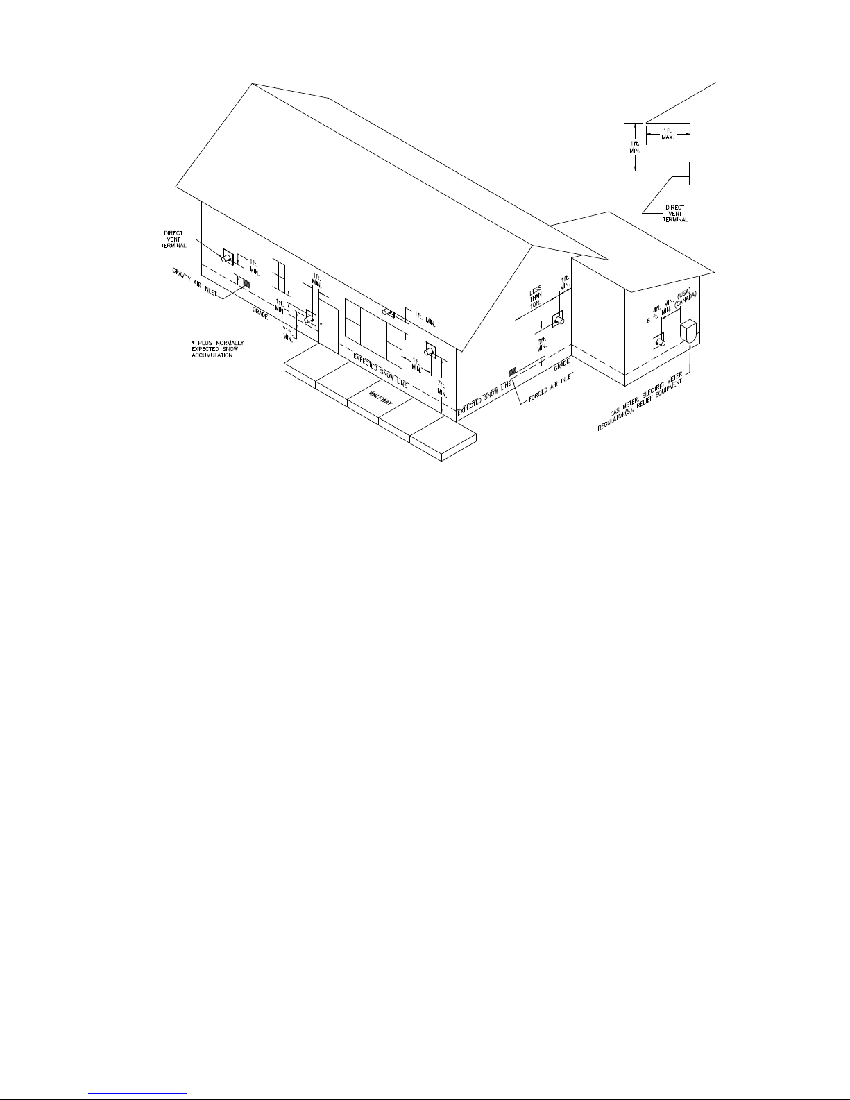
Figure 4: Location of Vent Terminal Relative to Windows, Doors, Grades, Overhangs, Meters and Forced Air
Inlets (Concentric Terminal Shown - Two-Pipe System Vent Terminal to be installed in same location Two-Pipe System Air Intake Terminal Not Shown)
b. Maintain the correct clearance and orientation
between the vent and air intake terminals.
i. The centerlines between the vent and air
intake terminals must be spaced a minimum
of 12” apart. More than 12” spacing is
recommended.
ii. If possible, locate air intake and vent
terminations on the same wall to prevent
nuisance shutdowns. However, boiler may
be installed with vertical venting and sidewall
combustion air inlet or vice versa where
installation conditions do not allow for alternate
arrangement.
iii. The vent and air intake terminations may be
at varying heights when installed on the same
wall, but the height of the vent termination
should always be higher than the air intake
termination and within the specied limit as
shown in Figure 9B.
c. The bottom of the vent and air intake terminal must
be at least 12” (18” in Canada) above the normal
snow line. In no case should they be less than 12”
above grade level.
d. The bottom of the vent terminal must be at least 7
feet above a public walkway.
e. Do not install the vent terminal directly over
windows or doors.
f. The bottom of the vent terminal must be at least
3 feet above any forced air inlet located within 10
feet.
g. A clearance of at least 4 feet horizontally must
be maintained between the vent terminal and
gas meters, electric meters, regulators, and relief
equipment. Do not install vent terminal over this
equipment.
h. Do not locate the vent terminal under decks or
similar structures.
i Minimum twelve (12) inches vertically from any
roof overhang twelve (12) inches or less wide.
If a roof overhang width exceeds twelve (12) inches
the terminal vertical clearance must be increased
to avoid ue vapor condensation.
j. Top of vent terminal must be at least 5 feet below
eaves, softs, or overhangs. Maximum depth of
overhang is 3 ft.
k. If window and/or air inlet is within four (4) feet of
an inside corner, then terminal must be at least six
(6) feet from adjoining wall of inside corner.
l. Concentric - Minimum twelve (12) inches
horizontally from a building corner.
m. Under certain conditions, water in the ue gas may
condense, and possibly freeze, on objects around
the terminal including on the structure itself. If
these objects are subject to damage by ue gas
condensate, they should be moved or protected.
103448-02 - 6/13 21
Page 22
IV. Venting A. General Guidelines (continued)
B. CPVC/PVC Venting
n. If possible, install the vent and air intake terminals
on a wall away from the prevailing wind. Reliable
operation of this boiler cannot be guaranteed if the
terminal is subjected to winds in excess of 40 mph.
o. Air intake terminal must not terminate in areas that
might contain combustion air contaminates, such
as near swimming pools.
p. For sidewall venting the minimum horizontal
distance between any adjacent individual module
(boiler) vent terminations is twelve (12) inches.
Increasing this distance is recommended to avoid
frost damage to building surfaces where vent
terminations are placed.
CAUTION
Installing multiple individual module (boiler) vent
terminations too close together may result in cross
contamination and combustion product water
vapor condensation on building surfaces, where
vent termination are placed, and subsequent
frost damage. To avoid/minimize frost damage,
extend the distance from building surfaces to
vent termination end and increase the horizontal
distance between adjacent vent terminations.
q. The minimum horizontal distance between any
adjacent individual module (boiler) roof vent
terminations is one (1) foot.
7. Use noncombustible ¾" pipe strap to support
horizontal runs and maintain vent location and slope
while preventing sags in pipe. Do not restrict thermal
expansion or movement of vent system. Maximum
support spacing four (4) feet. Avoid low spots where
condensate may pool. Do not penetrate any part of
the vent system with fasteners.
8. Maintain minimum clearance to combustible materials.
See Figures 2A and 2B for details.
9. Enclose vent passing through occupied or unoccupied
spaces above boiler with the material having a re
resistance rating of at least equal to the rating of
adjoining oor or ceiling.
Note: For one or two family dwellings, re resistance
rating requirement may not need to be met, but is
recommended.
10. Multiple individual module vertical vent pipes may
be piped through a common conduit or chase so that
one roof penetration may be made.
WARNING
CPVC vent components must be used within any
interior space where air cannot circulate freely,
such as air inside a stud wall, and in any boiler
closet.
WARNING
When using the CPVC/PVC vent options, the use
of CPVC is required when venting in vertical or
horizontal chase ways.
1. Components and Length Restrictions
a. See Table 5A for CPVC/PVC Vent & Air Intake
Components included with boiler, Table 5B for
CPVC/PVC Vent and Air Intake Components
(Installer Provided) required for Optional
Horizontal (Snorkel) Termination and Table 5C
for CPVC/PVC Vent and Air Intake Components
(Installer Provided) required for Optional Vertical
(Roof) Termination.
WARNING
All condensate that forms in the vent must be
able to drain back to the boiler.
b. Vent length restrictions are based on equivalent
length of vent/combustion air pipe (total length
of straight pipe plus equivalent length of
ttings). Maximum vent/combustion air lengths
are listed in Table 8. Do not exceed maximum
vent/combustion air lengths. Table 6 lists
equivalent lengths for ttings. Do not include
vent/combustion air terminals in equivalent
feet calculations. See “Combustion Air/Vent,
Equivalent Length Work Sheet”.
c. The vent termination location is restricted as per
'General Guidelines', Paragraph A, 6.
(Refer to Figure 4).
System Assembly
2.
a. Plan venting system to avoid possible contact
with plumbing or electrical wires. Start at
vent connector at boiler and work towards vent
termination.
b. Do not exceed maximum Vent/Combustion Air
length. Refer to Table 8.
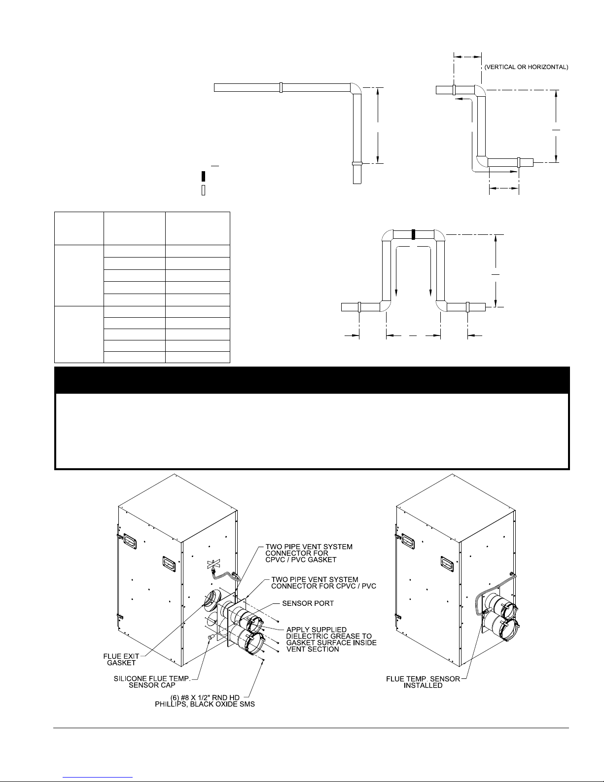
c. Design the Vent System to allow 3/8" of thermal
expansion per 10 feet of CPVC/PVC pipe. Runs
of 20 feet or longer that restrained at both ends
must use an offset or expansion loop. Refer to
Figure 5 and Table 7.
22 103448-02 - 6/13
Page 23
IV. Venting B. CPVC/PVC Venting (continued)
d. Follow all manufacturer instructions and
warnings when preparing pipe ends for joining
and using the primer and the cement.
3. Field Installation of CPVC/PVC Two-Pipe
Vent System Connector - Floor Mounted
Boiler Builds
Refer to Figure 6 and Steps below:
a. Position the CPVC/PVC vent connector and
gasket onto boiler rear/bottom panel and insert
vent connector inner stainless steel vent pipe into
b. Align vent connector plate and gasket clearance
holes with rear/bottom panel engagement holes;
than, secure the connector and gasket to the
panel with six mounting screws.
c. Apply supplied dielectric grease (grease pouch
attached to two-pipe vent connector) to gasket
inside vent section of two-pipe vent connector,
The grease will prevent gasket rupture when
inserting vent pipe and gasket deterioration due
to condensate exposure.
heat exchanger vent outlet.
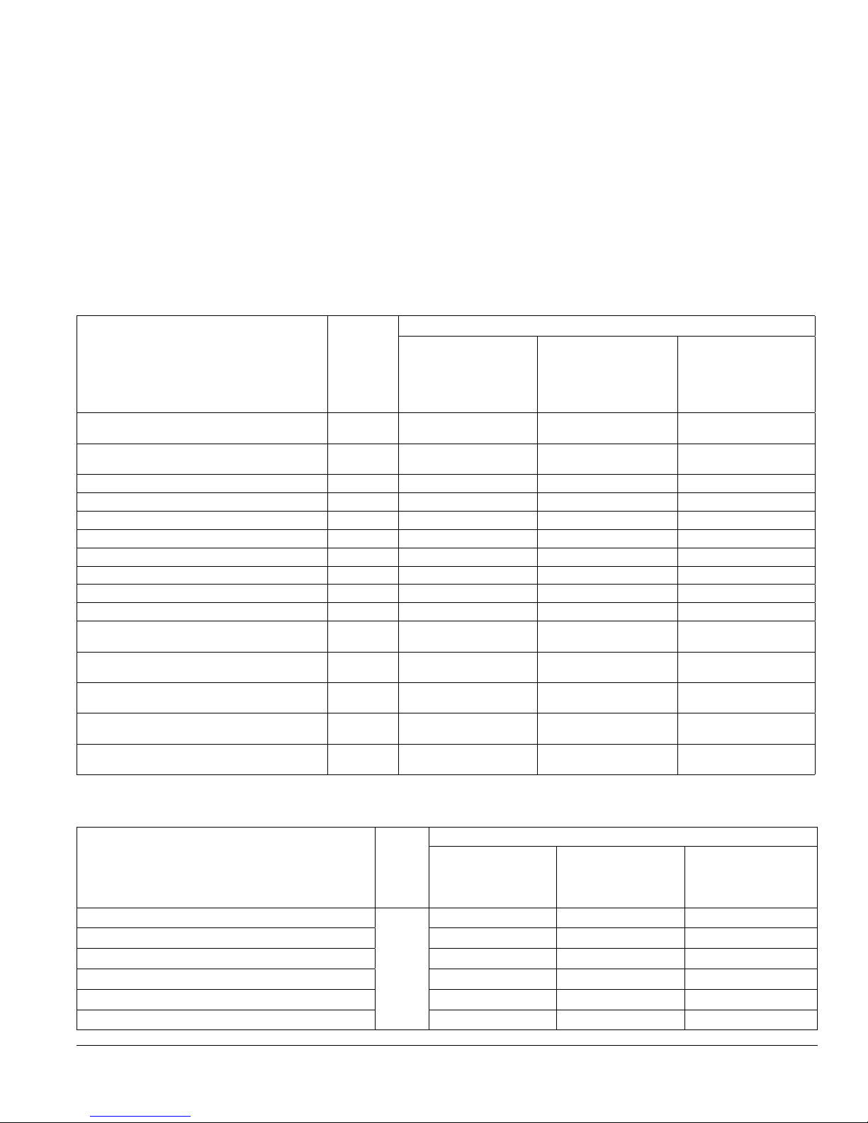
Table 5A: CPVC/PVC Vent & Air Intake Components Included With Boiler
Quantity
Vent & Air Intake Components
3” Schedule 40 PVC Tee (Vent & Air Intake
Terminals)
4” Schedule 40 PVC Tee (Vent & Air Intake
Terminals)
3” Stainless Steel Rodent Screen 102191-01 2 1 N/A
4” Stainless Steel Rodent Screen 102191-02 N/A 1 2
3” x 30” Schedule 40 CPVC Pipe 102193-01 1 1 N/A
4” x 30” Schedule 40 CPVC Pipe 102193-02 N/A N/A 1
3” Schedule 80 CPVC 90° Elbow 102192-01 1 1 1
4” Schedule 80 CPVC 90° Elbow 102192-02 N/A N/A 1
4 oz. Bottle of Transition Cement 102195-01 1 1 1
4 oz. Bottle of Primer 102194-01 1 1 1
3" Vent/3" Combustion Air CPVC/PVC
Connector
3" Vent/4" Combustion Air CPVC/PVC
Connector
4" Vent/4" Combustion Air CPVC/PVC
Connector
3" Vent/3" Combustion Air CPVC/PVC
Connector Gasket
4" Vent/4" Combustion Air CPVC/PVC
Connector Gasket
Part
Number
102190-01 2 1 N/A
102190-02 N/A 1 2
102183-01 1 N/A N/A
102183-02 N/A 1 N/A
102183-03 N/A N/A 1
102185-01 1 N/A N/A
102185-02 N/A 1 1
ALP080B & ALP105B
Standard Termination
Vent Kit
(P/N 102189-01)
includes
ALP150B & ALP210B
Standard Termination
Vent Kit
(P/N 102189-02)
includes
ALP285B thru
ALP399 Standard
Termination Vent Kit
(P/N 102189-03)
includes
Table 5B: CPVC/PVC Vent & Air Intake Components (Installer Provided) required for Optional Horizontal
(Snorkel) Termination
Vent Components
3" Schedule 40 PVC Pipe x up to 7 ft. max. vertical run
4" Schedule 40 PVC Pipe x up to 7 ft. max. vertical run N/A 1 2
3" Schedule 40 PVC 90° Elbow 4 2 N/A
4" Schedule 40 PVC 90° Elbow N/A 2 4
3" Schedule 40 PVC Pipe x ½ ft. min. horizontal run 2 1 N/A
4" Schedule 40 PVC Pipe x ½ ft. min. horizontal run N/A 1 2
103448-02 - 6/13 23
Part
Number
N/A
Supplied
by
Others
ALP080B &
ALP105B
Horizontal (Snorkel)
Termination
2 1 N/A
Quantity
ALP150B &
ALP210B
Horizontal (Snorkel)
Termination
ALP285B thru
ALP399
Horizontal (Snorkel)
Termination
Page 24
IV. Venting B. CPVC/PVC Venting (continued)
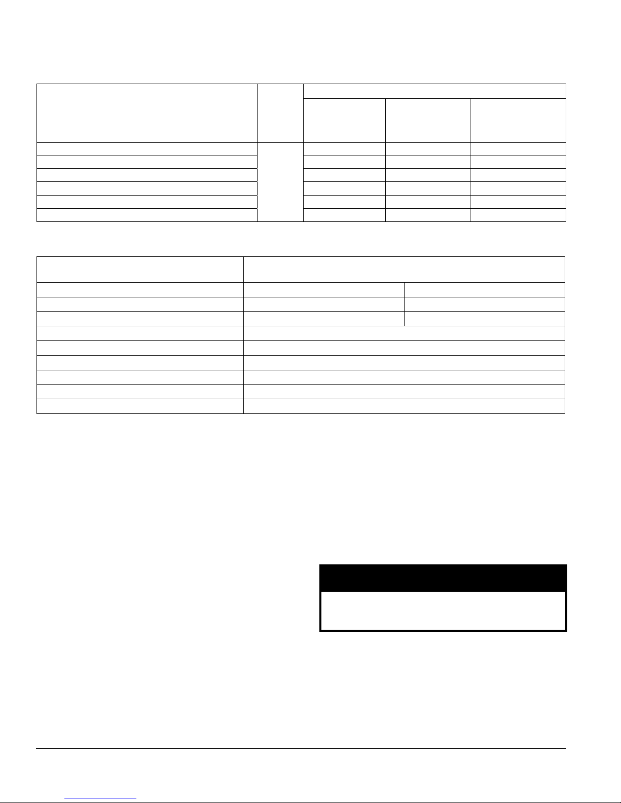
Table 5C: CPVC/PVC Vent & Air Intake Components (Installer Provided) required for Optional Vertical
(Roof) Termination
Quantity
Vent Components
3" Schedule 40 PVC Coupler
4" Schedule 40 PVC Coupler N/A 1 1
3" Schedule 40 PVC 90° Elbow 2 N/A N/A
4" Schedule 40 PVC 90° Elbow N/A 2 2
3" Schedule 40 CPVC Pipe x ½ ft. min. horizontal run 1 N/A N/A
4" Schedule 40 CPVC Pipe x ½ ft. min. horizontal run N/A 1 1
Part
Number
N/A
Supplied
by Others
ALP080B &
ALP105B
Vertical (Roof)
Termination
1 N/A N/A
Table 6: Vent System and Combustion Air System Components Equivalent Length
vs. Component Nominal Diameter
Vent or Combustion Air System
Component Description
Component Nominal Diameter, In. 3” 4”
90° Elbow (Sch. 80 or Sch. 40) 10 13
45° Elbow (Sch. 80 or Sch. 40) 3 4.5
Sch. 40 CPVC Pipe x 30 In. Long 2.5
Sch. 40 PVC Pipe x 1 Ft. Long 1
Sch. 40 PVC Pipe x 2 Ft. Long 2
Sch. 40 PVC Pipe x 3 Ft. Long 3
Sch. 40 PVC Pipe x 4 Ft. Long 4
Sch. 40 PVC Pipe x 5 Ft. Long 5
Equivalent Length (Ft.) for Vent or Combustion Air System Component
vs. Component Nominal Diameter (In.)
ALP150B &
ALP210B
Vertical (Roof)
Termination
ALP285B thru
ALP399
Vertical (Roof)
Termination
4. Near-Boiler Vent/Combustion Air Piping -
Floor Mounted Boiler Builds
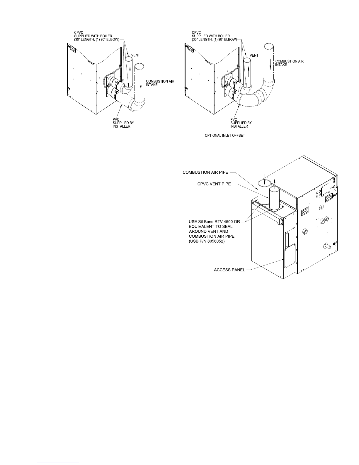
Refer to Figure 7A and the following Steps:
a. All CPVC vent components supplied with boiler
inside vent carton (3” or 4” Schedule 40 x 30”
long CPVC pipe and 3” or 4” Schedule 80 CPVC
90° Elbow) must be used for near-boiler piping
before transitioning to Schedule 40 PVC (ASTM
2665) pipe components for reminder of vent
system. The CPVC 30” long straight pipe may be
cut to accommodate desired vent conguration
provided both pieces are used in conjunction
with CPVC 90° Elbow before any PVC
components are used. Ensure that the CPVC 90°
Elbow is the rst elbow used in the vent system
as it exits the boiler.
The wall mounted boiler builds do not require using
3” Schedule 80 CPVC 90° Elbow for near-boiler
vent piping.
a. Insert provided 3” Schedule 40 x 30” long
CPVC pipe thru air box top combination vent/
combustion air collar vent opening and slide
down with a slight twisting motion, until the pipe
lower end is rmly inserted into female end of
factory installed vent connector 90° Elbow.
b. Secure the pipe by tightening the metal strap
worm screw.
WARNING
Failure to properly secure the vent into the elbow
with the clamp could lead to property damage,
personal injury or loss of life.
b. Clean all vent and combustion air pipe joints
with primer and secure with transition cement
(4-oz. bottles of primer and cement are
supplied with boiler inside vent carton). Follow
application instructions provided on primer and
cement bottles.
5. Field Installation of CPVC Vent Pipe - Wall
Mounted Boiler Builds
Refer to Figure 7B and the following Steps:
i. The CPVC 30” long straight pipe may be cut
to accommodate desired vent conguration.
If the CPVC 30” straight pipe needs to be
cut into two pieces to accommodate desired
vent conguration, insure that the rst
vertical piece has minimum length of 12
inches and extends 1-5/8” above air box top,
so a coupling or an elbow can be attached to
it.
24 103448-02 - 6/13
Page 25
IV. Venting B. CPVC/PVC Venting (continued)
CHANGE OF DIRECTION
(VERTICAL OR HORIZONTAL)
LONG RUN OF PIPE
L
4
OFFSET
Table 7: Expansion Loop Lengths
Nominal
Pipe Dia.
(In.)
3
Length of
Straight Run
(Ft.)
20 53
30 65
40 75
Loop Length
“L” (In.)
KEY
RESTRAINT (RESTRICTS MOVEMENT)
HANGER (ALLOWS MOVEMENT)
L
LOOP
(HORIZONTAL ONLY)
(TOP VIEW)
L
LOOP LENGTH
(L)
L
4
2 L
5
L
2
50 84
60 92
20 60
30 74
4
40 85
50 95
60 104
Figure 5: Expansion Loop and Offset
6"
MIN
L
5
6"
MIN
WARNING
Apply supplied silicon dielectric grease from attached pouch to gasket inside vent section of two-pipe vent
connector. Failure to apply the grease could result in gasket rupture during vent pipe installation and gasket
deterioration due to condensate exposure.
Check if ue exit gasket inside heat exchanger has factory applied silicon grease. If the gasket lubricant
is missing, apply supplied silicon dielectric grease prior to two-pipe vent connector insertion into heat
exchanger ue exit.
Figure 6: Field Installation of CPVC/PVC Two-Pipe Vent System Connector - Floor Mounted Boiler Builds
103448-02 - 6/13 25
Page 26
IV. Venting B. CPVC/PVC Venting (continued)
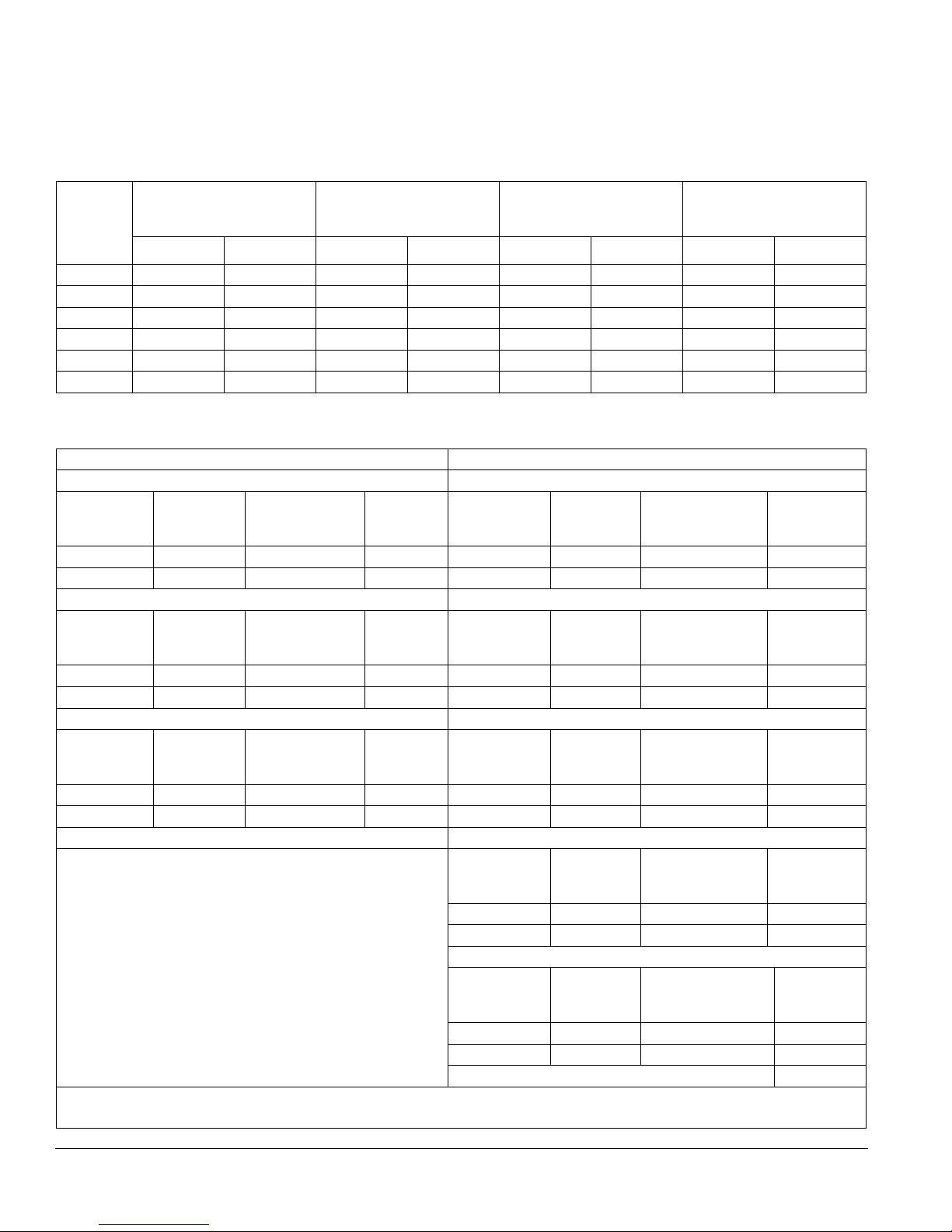
Table 8: Vent/Combustion Air Pipe Length – Two-Pipe Direct Vent System Options
• CPVC/PVC
• Polypropylene (PP) or Polypropylene (PP)/PVC
• Stainless Steel/PVC or Galvanized Steel)
3” (80 mm)
Boiler
Model
ALP080B 30 In. 135 Ft. 30 In. 135 Ft.
ALP105B 30 In. 135 Ft. 30 In. 135 Ft.
ALP150B 30 In. 135 Ft. 30 In. 135 Ft.
ALP210B 30 In. 135 Ft. 30 In. 135 Ft.
ALP285B 30 In. 100 Ft. 30 In. 100 Ft.
ALP399 30 In. 100 Ft. 30 In. 100 Ft.
Combustion Air Pipe
(Equivalent Length)
Min. Max. Min. Max. Min. Max. Min. Max.
4” (100 mm)
Combustion Air Pipe
(Equivalent Length)
3” (80 mm) Vent Pipe
(Equivalent Length)
4” (100 mm) Vent Pipe
(Equivalent Length)
Vent/Combustion Air Equivalent Length Calculation Work Sheet CPVC/PVC Two-Pipe
Combustion Air Vent
90° Elbow(s) PVC (Installer Supplied) 90° Elbow(s) CPVC (Supplied with Boiler)
Nominal
Diameter, In.
3 10 3 1 10 10
4 13 4 1 13 13
Nominal
Diameter, In.
3 3.0 3 10
4 4.5 4 13
Nominal
Diameter, In.
3 1 3 3.0
4 1 4 4.5
* Total Equivalent Length, Ft. (A+B+C) = 30” (2.5 Ft.) Straight Pipe, CPVC (Supplied with Boiler)
* Note: Total Equivalent Length Calculated Value Cannot Exceed Max. Equivalent Length Values shown in Table 8.
Vent and Combustion Air Terminals Do Not Count Towards Total Equivalent Length.
Quantity
(Pc)
45° Elbow(s) PVC (Installer Supplied) 90° Elbow(s) PVC (Installer Supplied)
Quantity
(Pc)
Straight Pipe, PVC (Installer Supplied) 45° Elbow(s) PVC (Installer Supplied)
Quantity
(Length, Ft.)
Equivalent
Length, Ft/Pc
Equivalent
Length, Ft/Pc
Equivalent
Length, Ft/Ft
Subtotal,
Equivalent
Ft. (A)
Subtotal,
Equivalent
Ft. (B)
Subtotal,
Equivalent
Ft. (C)
Nominal
Diameter, In.
Nominal
Diameter, In.
Nominal
Diameter, In.
Nominal
Diameter, In.
3 2.5 1 2.5
4 2.5 1 2.5
Nominal
Diameter, In.
3 1
4 1
* Total Equivalent Length, Ft. (A+B+C+D+E) =
Quantity
(Pc)
Quantity
(Pc)
Quantity
(Length, Ft.)
Quantity
(Length, Ft.)
Straight Pipe, PVC (Installer Supplied)
Quantity
(Length, Ft.)
Equivalent Length,
Ft/Pc
Equivalent Length,
Ft/Pc
Equivalent Length,
Ft/Ft
Equivalent Length,
Ft/Ft
Equivalent Length,
Ft/Ft
Subtotal,
Equivalent Ft.
(D)
Subtotal,
Equivalent Ft.
(A)
Subtotal,
Equivalent Ft.
(B)
Subtotal,
Equivalent Ft.
(E)
Subtotal,
Equivalent
Ft. (C)
26 103448-02 - 6/13
Page 27
IV. Venting B. CPVC/PVC Venting (continued)
Figure 7A: Near-Boiler Vent/Combustion Air Piping - Floor Mounted Boiler Builds
ii. The factory supplied CPVC vent pipe
(3” Schedule 40 x 30” long CPVC pipe)
must be used for near-boiler piping before
transitioning to Schedule 40 PVC (ASTM
2665) pipe components for reminder of vent
system.
iii. Clean all vent and combustion air pipe joints
with primer and secure with transition cement
(4-oz. bottles of primer and cement are supplied
with boiler). Follow application instructions
provided on primer and cement bottles.
c. Apply supplied dielectric grease (grease pouch
attached to 90° vent elbow outlet inside air
box) to gasket inside vent elbow. The grease
will prevent gasket rupture when inserting vent
pipe and gasket deterioration due to condensate
exposure.
6. Horizontal Vent Termination
a. Standard Two-Pipe Termination
See Figures 8 through 11.
i. Vent Piping
Running PVC vent pipe inside Enclosures and
thru Walls:
• PVC vent pipe must be installed in such
way as to permit adequate air circulation
around the outside of the pipe to prevent
internal wall temperature rising above
ANSI Z21.13 standard specied limit.
• Do not enclose PVC venting – use higher
temperature rated CPVC pipe in enclosed
spaces, or, to penetrate combustible or
non-combustible walls.
• PVC vent pipe may not be used to penetrate
combustible or non-combustible walls
unless all following three conditions are
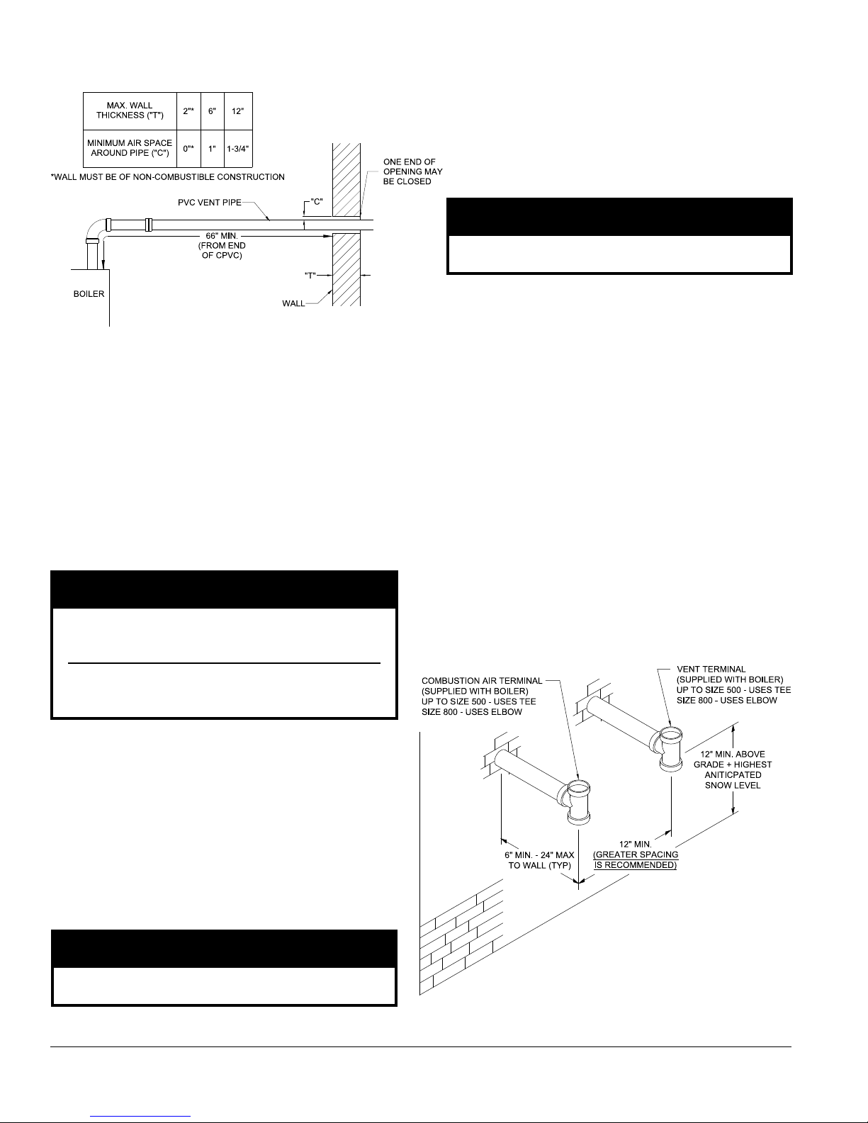
met simultaneously (see Figure 8 “ Wall
Penetration Clearances for PVC Vent
Pipe”):
103448-02 - 6/13 27
Figure 7B: Field Installation of CPVC Vent Pipe -
Wall Mounted Boiler Builds
- The wall penetration is at least 66 inches
from the boiler as measured along the
vent
- The wall is 12” thick or less
- An air space of at least of that shown in
Figure 8 is maintained around outside of
the vent pipe to provide air circulation
• If above three conditions cannot be
met simultaneously when penetrating a
combustible wall, use a single wall thimble
[US Boiler part numbers 102180-01 (3”)
and 102181-01 (4”)].
• Thimble use is optional for non-combustible
wall.
• Insert thimble into cut opening from outside.
Secure thimble outside ange to wall with
nails or screws and seal ID and OD with
sealant material.
Page 28
IV. Venting B. CPVC/PVC Venting (continued)
Figure 8: Wall Penetration Clearances for PVC Vent Pipe
• When thimble is not used for non-
combustible wall, size and cut wall opening
such that a minimal clearance is obtained
and to allow easy insertion of vent pipe.
• Apply sealant between vent pipe and
thimble or wall opening to provide weathertight seal. Sealant should not restrain the
expansion of the vent pipe.
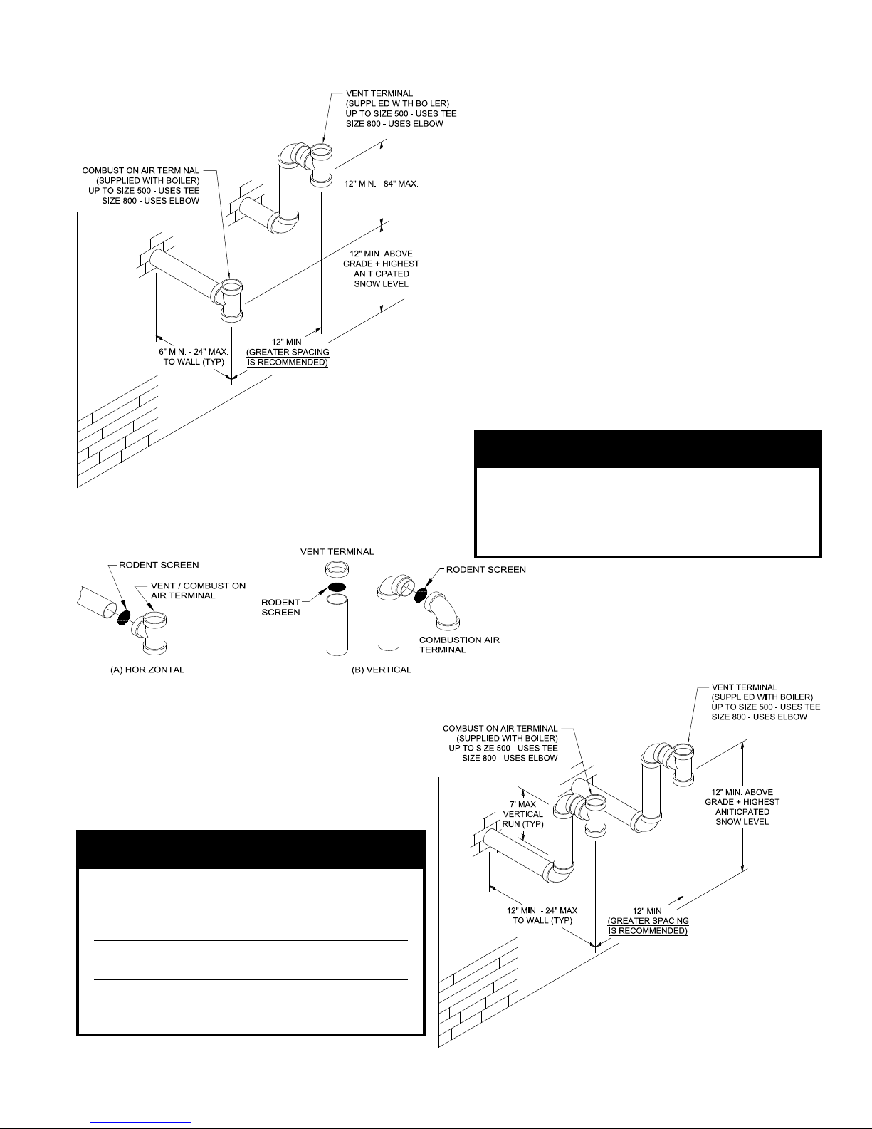
• Install Rodent Screen and Vent Terminal
(supplied with boiler). See Figure 10 for
appropriate conguration details.
WARNING
All CPVC pipe supplied with boiler vent carton
must be used as part of vent system prior to
connecting supplied PVC vent terminal.
Methods of securing and sealing terminals
to the outside wall must not restrain the
thermal expansion of the vent pipe.
b. Optional Two-Pipe Snorkel Termination
See Figures 10 and 11.
This installation will allow a maximum of seven (7)
feet vertical exterior run of the vent/combustion air
piping to be installed on the CPVC/PVC horizontal
venting application.
NOTICE
Exterior run to be included in equivalent vent/
combustion air lengths.
i. Vent Piping
• After penetrating wall, install a Schedule 40
PVC 90° elbow so that the elbow leg is in
the up direction.
• Install maximum vertical run of seven (7) feet
of Schedule 40 PVC vent pipe. See Figure
11.
• At top of vent pipe length install another PVC
90° elbow so that elbow leg is opposite the
building’s exterior surface.
• Install Rodent Screen and Vent Terminal
(supplied with boiler), see Figure 10 for
appropriate conguration.
• Brace exterior piping if required.
ii. Combustion Air Piping
• After penetrating wall, install a Schedule 40
PVC 90° elbow so that elbow leg is in the
up direction.
• Install maximum vertical run of seven (7) feet
of Schedule 40 PVC vent pipe. See Figure
11.
ii. Combustion Air Piping
• Do not exceed maximum combustion air
pipe length. Refer to Table 8.
• Size combustion air pipe wall penetration
opening to allow easy insertion of the pipe.
• Install Rodent Screen and Combustion Air
Terminal (supplied with boiler). See Figure
10 for appropriate conguration details.
• Apply sealant between combustion air pipe
and wall opening to provide weather-tight
seal.
CAUTION
To avoid cross-contamination, extend the
distance between adjacent vent terminations.
28 103448-02 - 6/13
Figure 9A : Direct Vent - Sidewall Terminations
Page 29
IV. Venting B. CPVC/PVC Venting (continued)
7. Vertical Vent Termination
a. Standard Two-Pipe Termination
Refer to Figures 8, 10, 12 and 13.
i. Vent Piping
• Install re stops where vent passes through
oors, ceilings or framed walls. The re
stop must close the opening between the
vent pipe and the structure.
• Whenever possible, install vent straight
through the roof. Refer to Figures 12 and
13.
- Size roof opening to maintain minimum
clearance of 1" from combustible
materials.
- Extend vent pipe to maintain minimum
vertical and horizontal distance of twelve
(12) inches from roof surface. Additional
vertical distance for expected snow
accumulation. Provide brace as required.
CAUTION
Figure 9B : Direct Vent - Sidewall Terminations
(Optional)
Figure 10: Rodent Screen Installation
• At top of air pipe length install another PVC
90° elbow so that elbow leg is opposite the
building’s exterior surface.
• Install Rodent Screen and Combustion Air
Terminal (supplied with boiler), see Figure
10 for appropriate conguration.
• Brace exterior piping if required.
WARNING
All CPVC supplied with the vent kit must be
used prior to connection of the vent system to
this terminal. If the vent system is too short
to permit this, do not use this terminal.
Do not operate boiler without the rain cap in
place.
Methods of securing and sealing terminals
to the outside wall must not restrain the
thermal expansion of the vent pipe.
Vertical venting and combustion air roof
penetrations (where applicable) require the use
of roof ashing and storm collar, which are not
supplied with boiler, to prevent moisture from
entering the structure.
- Install storm collar on vent pipe
immediately above ashing. Apply
Dow Corning Silastic 732 RTV Sealant
between vent pipe and storm collar to
provide weather-tight seal.
Figure 11: Direct Vent - Optional Sidewall
Snorkel Terminations
103448-02 - 6/13 29
Page 30

IV. Venting B. CPVC/PVC Venting (continued)
• Install Rodent Screen and Vent Terminal
(supplied with boiler), see Figure 10 for
appropriate conguration.
• Brace exterior piping if required.
ii.
Combustion Air Piping
• Locate combustion air termination on the
same roof location as the vent termination
to prevent nuisance boiler shutdowns.
Combustion air terminal can be installed
closer to roof than vent.
• Size roof opening to allow easy insertion
of combustion air piping and allow proper
installation of ashing and storm collar
to prevent moisture from entering the
structure.
- Use appropriately designed vent
ashing when passing through roofs.
Follow flashing manufacturers’
instructions for installation procedures.
- Extend combustion air pipe to maintain
minimum vertical and horizontal
distance of twelve (12) inches from
roof surface. Allow additional
vertical distance for expected snow
accumulation. Provide brace as
required.
- Install storm collar on combustion
air pipe immediately above ashing.
Apply Dow Corning Silastic 732 RTV
Figure 12: Direct Vent - Vertical Terminations
Sealant between combustion air pipe
and storm collar to provide weathertight seal.
• Install Rodent Screen and Combustion Air
Terminal (supplied with boiler), see Figure
10 for appropriate conguration.
• Brace exterior piping if required.
Extend vent/combustion air piping to maintain minimum vertical (‘X’) and minimum horizontal (‘Y’) distance of
twelve (12) inches (18 inches Canada) from roof surface. Allow additional vertical (‘X’) distance for expected
snow accumulation.
30 103448-02 - 6/13
Figure 13: Direct Vent - Vertical Terminations
with Sloped Roof
Page 31
IV. Venting C. Polypropylene Venting (continued)
WARNING
All CPVC supplied with the vent kit must be
used prior to connection of the vent system to
this terminal. If the vent system is too short
to permit this, do not use this terminal.
Do not operate boiler without the rain cap in
place.
Methods of securing and sealing terminals
to the outside wall must not restrain the
thermal expansion of the vent pipe.
C. Polypropylene Venting
Alpine boilers have been approved for use with
polypropylene vent system.
It is an installing contractor responsibility to procure
listed below polypropylene vent system pipe and related
components.
Polypropylene vent system manufactures are listed below:
Approved Polypropylene Vent System Manufacturers
Make Model
M&G/DuraVent
Centrotherm Eco
Systems
NOTE: Do not mix vent components from approved
manufacturers.
PolyPro Single Wall Rigid Vent
PolyPro Flex Flexible Vent
InnoFlue SW Rigid Vent
Flex Flexible Vent
M&G/DuraVent PolyPro Single Wall Rigid Vent and
PolyPro Flex Flexible Vent comply with the requirements
of ULC-S636-08 ‘Standard for Type BH Gas Venting
Systems’.
Centrotherm Eco Systems InnoFlue SW Rigid Vent
and Flex Flexible Vent comply with the requirements
of UL 1738 ‘Standard for Safety for Venting Systems’
and ULC-S636-08 ‘Standard for Type BH Gas Venting
Systems’.
For polypropylene vent system installation details refer
to an approved manufacturer either Rigid Single Wall
Polypropylene Vent Installation Instructions, or Flexible
Polypropylene Vent Installation Instructions provided with
a manufacturer specic kits. See Tables 9 and 10 below.
Refer to Table 8 ‘Vent/Combustion Air Pipe Length –
Two-Pipe Direct Vent System Options’ for minimum and
maximum listed equivalent length values.
All terminations must comply with listed options for two-
pipe venting system. See Figures 8 thru 12 for details.
When using exible polypropylene vent pipe (liner):
• Flexible pipe must be treated carefully and stored
at temperatures higher than 41°F (5°C).
• Do not bend or attempt to install exible pipe if
it has been stored at lower ambient temperature
without allowing the pipe to warm up to a higher
temperature rst.
Table 9: Approved Polypropylene Pipe, Fittings and Terminations - M&G/DuraVent
M&G / DuraVent Part Numbers/Sizes
Boiler
Model
ALP080B
ALP105B
ALP150B
ALP210B
ALP285B
ALP399
Boiler Adapter,
PVC to PP
3PPS-AD
3PPS-AD
and 4PPS-AD
4PPS-AD 100 mm 100 mm 4PPS-LB 4PPS-TB 4PPS-FK
Boiler
Adapter
Connector
PPS-PAC
Rigid Pipe Flex Pipe
80 mm 80 mm 3PPS-LB 3PPS-TB
80 mm
and 100 mm
80 mm
and 100 mm
Pipe Joint
Locking Band
3PPS-LB
and 4PPS-LB
Side Wall
Termination Tee
3PPS-TB
4PPS-TB
Table 10: Approved Polypropylene Pipe, Fittings and Terminations - Centrotherm Eco
Centrotherm Eco Part Numbers/Sizes
Boiler
Model
ALP080B
ALP105B
ALP150B
ALP210B
ALP285B
ALP399
Boiler Adapter,
PVC to PP
ISAA0303
ISSAL0303
ISAA0303
ISSAL0303
ISAA0404
ISSAL0404
ISAA0404
ISSAL0404
Boiler
Adapter
Connector
N/A
Rigid Pipe Flex Pipe
80 mm 80 mm IANS03 ISTT03
80 mm
and 110 mm
110 mm 110 mm IANS04 ISTT04
80 mm
and 110 mm
Pipe Joint
Locking Band
IANS03
and
IANS04
Side Wall
Termination Tee
ISTT03
ISTT04
and
Chimney Kit for
Venting Only
3PPS-FK
Chimney Kit for
Venting Only
IFCK0325
and
IFCK0335
IFCK0425
and IFCK0435
103448-02 - 6/13 31
Page 32
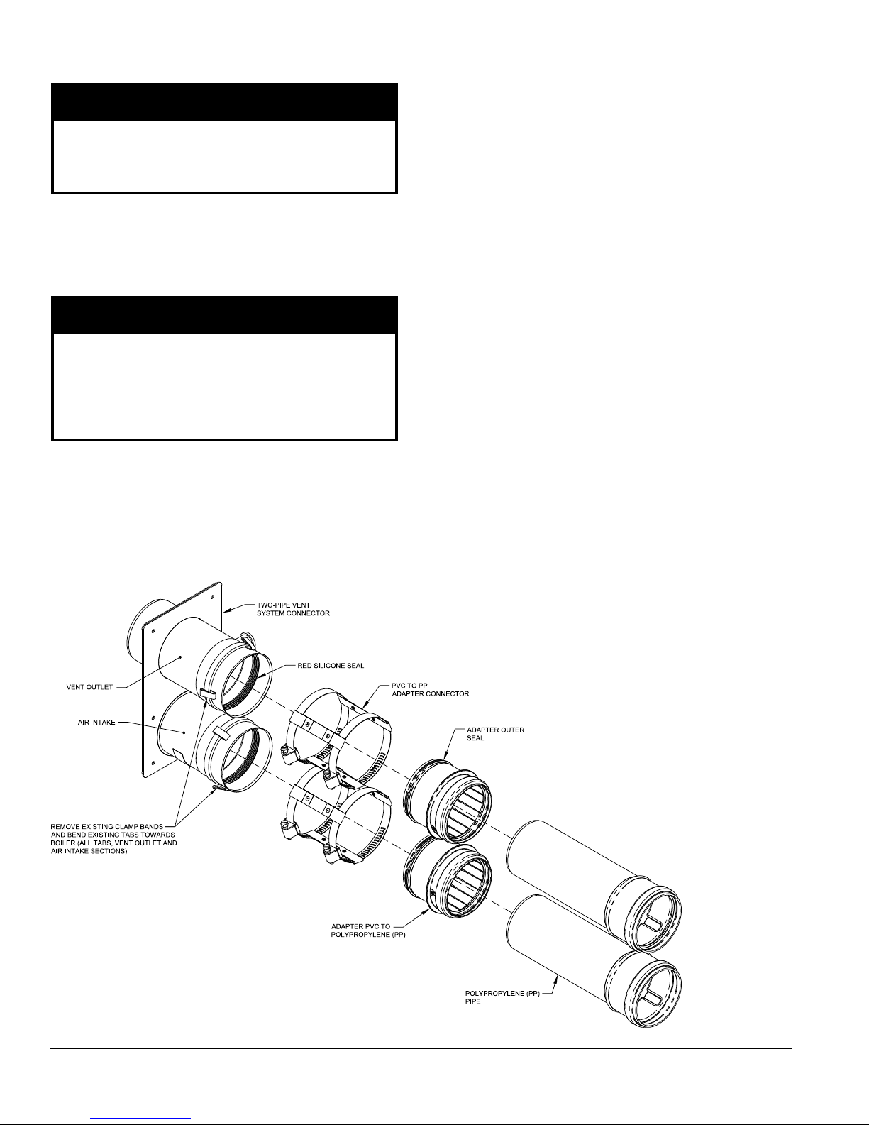
IV. Venting C. Polypropylene Venting (continued)
CAUTION
Bending or attempting to install exible pipe if it
has been stored at ambient temperature below
41°F (5°C) will cause material to become brittle
and lead to cracks.
• When exible polypropylene pipe (liner) is used
for combustion product venting, it must not be
installed at an angle greater than 45 degrees
from vertical plane. This will insure proper
condensate ow back towards the boiler.
CAUTION
Do not install exible polypropylene pipe at an
angle greater than 45 degrees from vertical plane
when used for combustion product venting.
Failure to do so will result in improper condensate
drainage towards the boiler and possible
subsequent vent pipe blockage.
• When exible polypropylene pipe (liner) is used
for combustion air supply to a boiler, the pipe
(liner) can be installed in vertical or horizontal
position.
• Follow flexible polypropylene pipe (liner)
manufacturer specic installation instructions
regarding application/listing, permits, minimum
clearances to combustibles; installation details
(proper joint assembly, pipe support and routing,
gasket and tting installation, optional tooling
availability/usage, routing thru masonry chimney
for combustion product venting or, combination
of combustion product venting and combustion
air supply).
• When there is a conflict between flexible
polypropylene pipe (liner) manufacturer
installation instructions and Alpine boiler
Installation, Operating and Service Instructions,
the more restrictive instructions shall govern.
Alpine Boiler Two-Pipe Vent System Connector Field
Modication Procedure To Accept Polypropylene Vent
Piping – Floor Mounted Boiler Builds:
Alpine oor mounted boilers are factory supplied with a
model-specic boiler two-pipe CPVC/PVC vent system
connector shipped within a model-specic boiler CPVC
gasketed vent kit carton.
Locate and remove a model-specic boiler two-pipe CPVC/
PVC vent system connector.
When using M&G/DuraVent polypropylene pipe for
combustion product venting modify the two-pipe vent
system connector upper vent connection port (has a ue
temperature sensor port welded on the side) to accept a
PVC to PP boiler adapter, as follows (See Figure 14 ):
Figure 14: Vent System Field Modication to Install PVC to PP Adapter (M&G/DuraVent Shown)
32 103448-02 - 6/13
Page 33
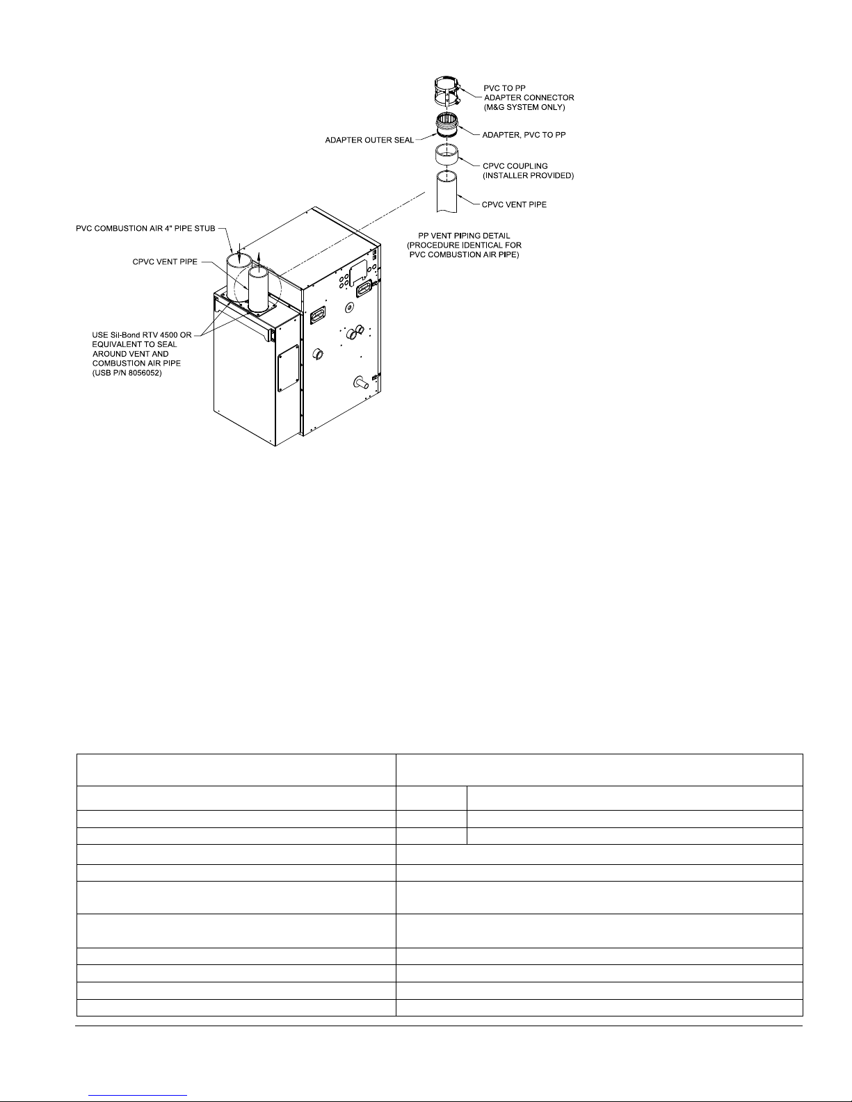
IV. Venting C. Polypropylene Venting (continued)
1) Remove external worm band clamp from upper
vent connection port of the two-pipe vent system
connector.
2) Using needle nose pliers grasp one of three spot
welded band clamp straps, close to a spot weld, and
reverse bend towards vent system connector body.
3) Repeat the same with two remaining clamp straps.
4) Apply provided dielectric grease (grease pouch
taped to the vent system connector) all around to
the vent connection inner red silicon gasket.
5) Lubricate PVC to PP boiler adapter (3PPS-AD or
4PPS-AD as applicable) outer seal with water, than,
push and twist the adapter into the vent connection
port until bottomed out.
Figure 15: Field Installation Procedure to Accept
Polypropylene Vent Piping - Wall Mounted Boiler
6) Install boiler adapter connector PPS-PAC to secure
PVC to PP boiler adapter to the vent connection
port of boiler two-pipe system connector.
7) Attach modied two-pipe system adapter to boiler.
See Figure 5 for details.
8) Lubricate PVC to PP boiler adapter inner seal with
water, than, push and twist a rigid PP pipe male
end into PVC to PP boiler adapter female end until
bottomed out.
9) When also using M&G/DuraVent polypropylene
pipe for combustion air supply to boiler repeat the
step 1 to modify the lower combustion air supply
port of the vent system connector to accept PVC
to PP boiler adapter.
10) Do not modify the lower combustion air supply port
of the two-pipe vent system connector when using
PVC pipe for combustion air supply to boiler.
When using Centrotherm Eco polypropylene pipe for
combustion product venting and/or air supply PVC to PP
boiler adapter (ISAA0303 or ISAA0404 as applicable) is
installed into the two-pipe vent system connector vent or
combustion air supply port as follows:
Table 11: Polypropylene Vent System and Combustion Air System Components Equivalent Length vs.
Component Nominal Diameter
Vent or Combustion Air System
Component Description
Component Nominal Diameter, mm 80 mm 100 mm (110 mm)
87° Elbow 10 13
45° Elbow 3.0 4.5
Rigid Single Wall 80 mm Polypropylene Pipe x 1 ft. 1
Rigid Single Wall 80 mm Polypropylene Pipe x L ft. long Multiply L by 1
Rigid Single Wall 100 mm (110 mm)
Polypropylene Pipe x 1 ft.
Rigid Single Wall 100 mm (110 mm)
Polypropylene Pipe x L ft. long
Flexible 80 mm Polypropylene Pipe x 1 ft. 1.2
Flexible 80 mm Polypropylene Pipe x L ft. long Multiply L by 1.2
Flexible 100 mm (110) Polypropylene Pipe x 1 ft. 1.2
Flexible 100 mm (110) Polypropylene Pipe x L ft. long Multiply L by 1.2
103448-02 - 6/13 33
Equivalent Length (Ft.) for Vent or Combustion Air System
Component vs. Component Nominal Diameter (mm)
1
Multiply L by 1
Page 34
IV. Venting C. Polypropylene Venting (continued)
11) Apply provided dielectric grease (grease pouch
taped to the vent system connector) all around to
the vent or air connection inner red silicon gasket.
12) Push and twist PVC to PP boiler adapter (ISAA0303
or ISAA0404 as applicable) into two-pipe vent
system connector vent connection or air supply
port until bottomed out.
13) Tighten the worm band clamp screw to secure PVC
to PP boiler adapter.
14) Do not install PVC to PP boiler adapter at the
lower combustion air supply port of the two-pipe
vent system connector when using PVC pipe for
combustion air supply to boiler.
Alpine Boiler Two-Pipe Vent System Field Installation
Procedure To Accept Polypropylene Vent Piping – Wall
Mounted Boiler Builds:
Alpine wall mounted boiler builds have a factory installed
vent connector 90° elbow inside air box and air box top
located combustion air collar, See Part B ‘CPVC/PVC
To accept polypropylene piping for venting and/or
combustion air (see Figure 15 “Field Installation Procedure
to accept Polypropylene Vent Piping – Wall Mounted
Boiler”
15) Install supplied 30” long CPVC pipe into a factory
installed vent connector 90° elbow and secure with
the elbow band clamp.
16) When using polypropylene pipe for combustion air
intake, install a 4” stub of an appropriate diameter
PVC air intake pipe (contractor supplied) onto air
box top located combustion air collar. Seal the stub
to air box top with silicon all around.
17) Attach and cement an appropriate diameter CPVC
coupling (contractor supplied) to previously
installed 30” long CPVC pipe exposed end.
18) If using polypropylene pipe for combustion air
intake, attach and cement an appropriate diameter
PVC coupling (contractor supplied) to exposed end
of PVC air intake stub.
Venting’, section ‘Field Installation of CPVC Vent Pipe
– Wall Mounted Boiler Builds’ and Figure 6B for details.
Vent/Combustion Air Equivalent Length Calculation Work Sheet for Rigid Polypropylene (PP) Vent
and Air Intake Two-pipe System
Combustion Air - Polypropylene (PP) Vent - Polypropylene (PP)
87° Elbow(s) PP (Installer Supplied) 87° Elbow(s) PP (Installer Supplied)
Nominal
Diameter, mm
80 10 80 1 10
100
(110)
Nominal
Diameter, In.
80 3.0 80 3.0
100
(110)
Nominal
Diameter, In.
80 1 80 1
100
(110)
* Total Equivalent Length, Ft. (A+B+C) =
Notes:
Maximum listed exible polypropylene liner length is 48 feet.
Pressure drop for exible polypropylene pipe (liner) is 20% higher than pressure drop for rigid polypropylene pipe. When calculating
Total Equivalent Length for a particular venting application where exible polypropylene pipe (liner) is to be used in combination with straight
rigid polypropylene pipe, multiply projected measured length of exible polypropylene pipe (liner) by 1.2 to arrive at corresponding
equivalent length of straight rigid polypropylene pipe.
Example:
Projected measured length of exible polypropylene pipe (liner) is 35 feet. Equivalent length of straight rigid polypropylene pipe to be used for
Total Equivalent Length calculation is 35 * 1.2 = 42 feet
Quantity
(Pc)
45° Elbow(s) PP (Installer Supplied) 45° Elbow(s) PP (Installer Supplied)
Quantity
(Pc)
Straight Pipe, PP (Installer Supplied) Straight Pipe, PP (Installer Supplied)
Quantity
(Length, Ft.)
Equivalent
Length, Ft/Pc
13
Equivalent
Length, Ft/Pc
4.5
Equivalent
Length, Ft/Ft
1
Subtotal,
Equivalent
Ft. (A)
Subtotal,
Equivalent
Ft. (B)
Subtotal,
Equivalent
Ft. (C)
Nominal
Diameter, mm
100
(110)
Nominal
Diameter, In.
100
(110)
Nominal
Diameter, In.
100
(110)
* Total Equivalent Length, Ft. (A+B+C) + 2.5** =
** Add 2.5 ft (30”) Straight Pipe, CPVC (Supplied with Boiler)
if used)
Quantity
(Pc)
1 13
Quantity
(Pc)
Quantity
(Length, Ft.)
Equivalent Length,
Ft/Pc
Equivalent Length,
Ft/Pc
4.5
Equivalent Length,
Ft/Ft
1
Subtotal,
Equivalent Ft.
(A)
Subtotal,
Equivalent Ft.
(A)
Subtotal,
Equivalent Ft.
(B)
34 103448-02 - 6/13
Page 35
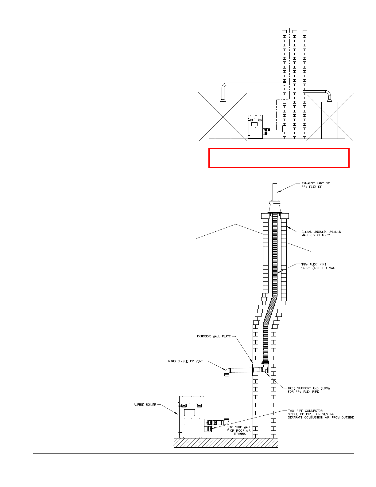
IV. Venting C. Polypropylene Venting (continued)
19) Lubricate PVC to PP adapter outer seal with water
(or approved water based lubricant), than, insert and
push lubricated adapter end into CPVC coupling
open end until bottomed out.
20) If using polypropylene pipe for combustion air
intake, repeat the above step installing the adapter
into PVC air intake.
21) Install the adapter connector (applicable to M&G/
DuraVent vent system only) to secure PVC to PP
adapter to a coupling and a polypropylene rigid
pipe, either venting and/or air intake.
Table 11 provides polypropylene venting or combustion
air supply system component equivalent length values to
calculate the equivalent vent length.
Optional Two-pipe Vertical Venting Installation –
Running Flexible Polypropylene Vent (Liner)
Thru Unused Chimney Chase (see Figure 16).
Alpine boilers are approved for vertical venting by
installing Flexible Vent in an UNUSED masonry
chimney/chase and supplying combustion air thru a
separate wall or roof air intake terminal.
Figure 16: Flexible Vent in Masonry Chimney
with Separate Air Intake
Venting of Other Appliances (or Fireplace)
into Chase or Adjacent Flues Prohibited!
103448-02 - 6/13 35
Page 36
IV. Venting C. Polypropylene Venting (continued)
WARNING
Follow installation instructions included by the original polypropylene venting component manufacturers,
M&G/DuraVent or Centrotherm, whichever applicable.
Flexible Polypropylene Vent must be installed in an UNUSED chimney. A chimney, either single or
multiple ue type, is considered UNUSED when none of the ues is being used for any appliance
venting.
Where one of the multiple ues is being used for an appliance venting, the exible vent installation is
not permitted thru any of adjacent ues.
Observe all precautions outlined in either M&G/DuraVent or Centrotherm instructions in addition to
those outlined in these instructions.
Examine all components for possible shipping damage prior to installation.
Proper joint assembly is essential for safe installation.
The venting system must be free to expand and contract and supported in accordance with installation
instructions included by the original polypropylene venting component manufacturers, M&G/DuraVent
or Centrotherm, whichever applicable.
Do not mix vent components or joining methods for different vent systems.
Where a conict arises between M&G/DuraVent or Centrotherm instructions and these instructions, the
more restrictive instructions shall govern.
Do not apply thermal insulation to vent pipe and ttings.
Do not obtain combustion air from within the building.
Table 12: Summary of PP Flex Two-Pipe Direct Vent System Option
Approved Two-Pipe Direct Vent System Option
Classication Used In These Instructions
Vent Exhaust Penetration Thru Structure Chimney Cap
Air Intake Penetration Thru Structure Side Wall or Roof terminal
Min. Round Chase Inside Diameter, inch 5 6
Min. Rectangular Chase Inside Dimensions, inch 5 x 5 6 x 6
Nominal Poly Pro Flex (M&G/DuraVent) Liner Size, mm 80 100
Nominal Flex (Centrotherm Eco) Liner Size, mm 80 110
Maximum Total Equivalent Vent Length (Including Flexible Vent Liner in Chase), ft
ALP080B
ALP105B
ALP150B
ALP210B
ALP285B
ALP399
Maximum Actual Length of Flexible Polypropylene Liner, ft 48 48
Maximum Equivalent Length of Flexible Polypropylene Liner, ft 58 58
UNUSED Chimney Chase Installation -
Flexible Vent Pipe and separate Air Intake
M&G/DuraVent Poly Pro Flex
Centrotherm Eco Flex
135 NA
NA 100
36 103448-02 - 6/13
Page 37
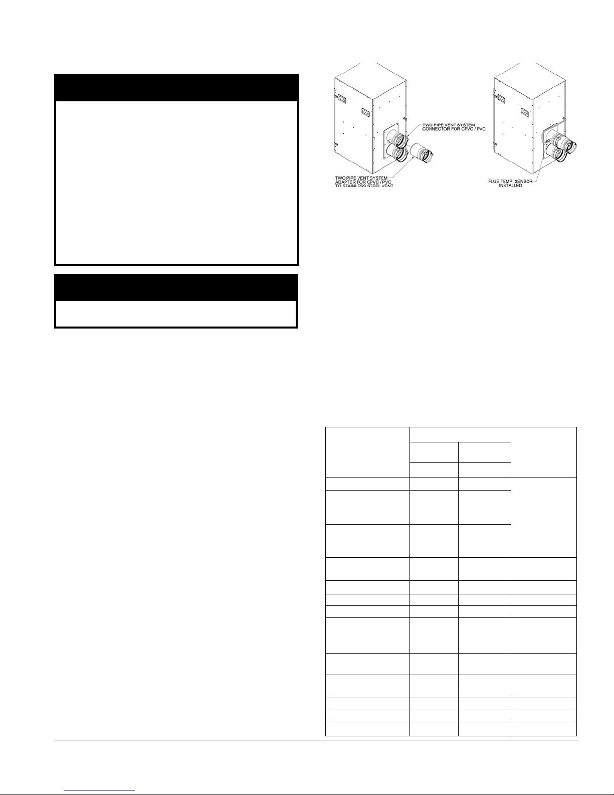
IV. Venting D. Stainless Steel Venting (continued)
D. Stainless Steel Venting
CAUTION
Vent systems made by Heat Fab, Protech and
Z-Flex rely on gaskets or proper sealing. When
these vent systems are used, take the following
precautions:
• Make sure that gasket is in position and un-
damaged in the female end of the pipe.
• Make sure that both the male and female
pipes are free of damage prior to assembly.
• Only cut vent pipe as permitted by the vent
manufacturer in accordance with their in structions. When pipe is cut, cut end must
be square and carefully de-burred prior to
assembly.
WARNING
All condensate that forms in the vent must be
able to drain back to the boiler.
1. Vent Length Restrictions
a. Vent length restrictions are based on equivalent
length of vent/combustion air pipe (total length
of straight pipe plus equivalent length of ttings).
Maximum vent/combustion air lengths are listed in
Table 8. Do not exceed maximum vent/combustion
air lengths. Do not include vent/combustion air
terminals in equivalent feet calculations. See
“Combustion Air/Vent, Equivalent Length Work
Sheet”.
b. The vent termination location is restricted as per
‘General Guidelines’, Paragraph A.5. (Refer to
Figure 4)
c. Where the use of “silicone” is called for in the
following instructions, use GE RTV 106 or
equivalent for the vent collar. Air inlet piping
sections are sealed with any general-purpose
silicone sealant such as GE RTV102. PVC air inlet
piping sections are connected with PVC cement.
d. Longitudinal welded seams should not be placed at
the bottom of horizontal sections of exhaust pipe.
e. Do not drill holes in vent pipe.
f. Do not attempt to mix vent components of different
vent system manufacturers.
2.
Near Boiler Connection
To install the stainless steel vent adapter
[P/N 102219-01 (3”). 102220-01 (4”)]:
a. Push the stainless steel vent adapter onto the CPVC/
PVC connector with a slight twisting motion. Make
sure that the stainless steel vent adapter is inserted
at least 1” (refer to Figure 17).
Figure 17: Field Installation of Two-Pipe Vent
System Adapter for Stainless Steel
b. Secure the adapter to the CPVC/PVC connector by
tightening the metal strap.
System Assembly
3.
a. Plan venting system to avoid possible contact with
plumbing or electrical wires. Start at vent connector
at boiler and work towards vent termination.
b. Refer to Tables 13A and 13B for approved AL29C
Vent Systems.
c. Do not exceed maximum Vent/Combustion air
length. Refer to Table 8.
d. Follow all manufacturer instructions and warnings
when preparing pipe ends for joining and using the
primer and the cement.
Table 13A: U.S. Boiler Company Vent System
Components (Stainless Steel)
Part Numbers
Vent System
Component
SS Vent Kit 102501-01 102501-02
Horizontal Vent
Terminal
(Included in Kit)
PVC to SS Vent
Adapter
(Included In Kit)
Vertical Vent Terminal 102680-01 102680-02 N/A
Pipe x 1 Ft. 8116296U 100176-01 1
Pipe x 3 Ft. 8116298U 100177-01 3
Pipe x 5 Ft. 8116300U 100178-01 5
Pipe x Adjustable 8116319U 100179-01
90° Elbow 8116294U 100180-01
45° Elbow 8116292U 100181-01
Horizontal Drain Tee 8116302U 100182-01 2
Vertical Drain Tee 8116304U 100183-01 7½
Single Wall Thimble 8116116 100184-01 N/A
ALP080B -
210B
3" Vent 4" Vent
8116310 8116313
102219-01 102220-01
ALP285B -
399
Equivalent
Feet of Pipe
N/A
Equal to
Installed Length
(1.06 to 1.64)
5.5 (3")
8.0 (4")
4.0 (3")
4.5 (4")
103448-02 - 6/13 37
Page 38
IV. Venting D. Stainless Steel Venting (continued)
Table 13B: Alternate Vent Systems and Vent Components (Stainless Steel)
Manufacturer
Protech
Systems
Inc..
Z-Flex
Flex-L Intl. Star-34
NOTE: See vent system manufacturer’s literature for other part numbers that are required such as straight pipe, elbows, restops
and vent supports.
Vent
System
FasNseal
SVE
Series III
(“Z-Vent III”)
Size Wall Thimbles Horizontal Termination
3 FSWT3 Tee: FSTT3 FSBS3
4 FSWT4 Tee: FSTT4 FSBS4
3 2SVSWTEF03 Tee: 2SVSTTF03 24SVSTPF03
4 2SVSWTEF04 Tee: 2SVSTTF04 24SVSTPF04
3 SR03WT15 Tee: SRTT-03 SRTP-03
4 SR04WT15 Tee: SRTT-04 SRTP-04
• Install a rodent screen (not supplied) in the
e. Assemble the air intake system using either
galvanized or PVC pipe.
i. If PVC piping is used, use PVC cement to
assemble the PVC intake system components.
See Part B for air intake installation instructions.
ii. If galvanized piping is used, use at least two
sheet metal screws per joint. Seal the outside
of all joints.
Horizontal Vent Termination
4.
a. Standard Two-Pipe Termination
Refer to Figure 9A.
i. Vent Termination
• Use U.S. Boiler Company stainless
exhaust terminal [P/N 8110701 (3”), or
P/N 100184-01 (4”)]. The outer edge of
this terminal must be between 6” and 12”
from the surface of the wall.
The joint between the terminal and the
last piece of pipe must be outside of the
building.
• Male end of terminal will t into the female
end of any of the approved stainless vent
systems.
• Apply a heavy bead of silicone to the male
end of the terminal before inserting it into
the last piece of pipe. Orient the terminal
so that the seam in the terminal is at 12:00.
• Smooth the silicone over the seam between
the terminal and the last piece of pipe,
applying additional silicone if necessary
to ensure a tight seal.
• Allow the silicone to cure per the
silicone manufacturer’s instructions before
operating the boiler.
ii. Combustion Air Termination
• Horizontal intake terminal is a tee in the
upright position. Tee should protrude the
same distance from the wall as the exhaust
terminal. See Figure 9A.
b. Optional Two-Pipe Snorkel Termination
Refer to Figure 11.
This installation will allow a maximum of seven
(7) feet vertical exterior run of the vent/combustion
air piping to be installed on the approved AL29C
Stainless Steel horizontal venting application.
i. Vent Termination
ii. Combustion Air Termination
5.
Vertical Vent Termination
a. Standard Two-Pipe Termination
Refer to Figures 12 and 13.
i. Vent Termination
inlet terminal. Use a screen having 1/2”
(2 x 2) or larger mesh.
• After penetrating wall, install the
appropriate manufacturer’s 90° elbow so
that the elbow leg is in the up direction.
• Install maximum vertical run of seven (7)
feet of appropriate manufacturer’s vent
pipe. See Figure 11.
• At top of vent pipe length install another
appropriate manufacturer’s 90° elbow so
that the elbow leg is opposite the building’s
exterior surface.
• Install horizontal vent terminal.
• Brace exterior piping if required.
• After penetrating wall, install a 90° elbow
so that the elbow leg is in the up direction.
• Install maximum vertical run of seven (7)
feet of combustion air pipe. See Figure 11.
• At top of vent pipe length install another
90° elbow os that the elbow leg is opposite
the building’s exterior surface.
• Install Rodent Screen (not supplied) and
horizontal vent terminal.
• Brace exterior piping if required.
• Use the terminal supplied by the vent
system manufacturer shown in Table 13B.
Vertical
Termination
38 103448-02 - 6/13
Page 39
IV. Venting D. Stainless Steel Venting (continued)
Follow manufacturer’s instructions to
attach terminal to vent system.
ii. Combustion Air Termination
• Install vertical combustion air terminal.
Vertical combustion air terminal consists
of an 180° bend (comprised of two (2) 90°
elbows) as shown in Figure 12.
• Install rodent screen (not supplied) in the
combustion air terminal. Use a screen
having 1/2” (2 x 2) or larger mesh.
E. Concentric Polypropylene Venting
1. Vent Length Restrictions
a. Vent length restrictions are based on equivalent
length of vent pipe i.e. total length of straight pipe
plus equivalent length of ttings. See Table 14
for specied vent length details. Do not exceed
maximum vent length. Table 15 lists available
concentric vent components and includes equivalent
vent length for ttings.
b. The vent termination location is restricted as per
‘General Guidelines’, Paragraph A, 5 (refer to
Figure 4).
Table 15: Concentric Vent Components
Part Number Component Description Size
101493-01 90° Elbow – Long Radius 80/125 mm 5.5
101491-01 45° Elbow - Long Radius 80/125 mm 3.0
101163-01 Cut -To-Length Extension, 500 mm (19-1/2”) 80/125 mm 1.63 **Can be cut
101162-01 Cut -To-Length Extension, 1000 mm (39”) 80/125 mm 3.25 **Can be cut
101485-01 Fixed Extension, 2000 mm (78”) 80/125 mm 3.25 ***Must not be cut
101808-01 Horizontal (Wall) Terminal 80/125 mm *NA Supplied with boiler
101495-01 Vertical Roof Terminal 80/125 mm *NA See Note 1
101496-01 Flat Roof Flashing 80/125 mm
101497-01 Sloped Roof Flashing 80/125 mm See Note 2
101492-01 Support Elbow with Chimney Chase Bracket 80/125 mm 8.5 See Note 3
101498-01 Hanger Wall Bracket 80/125 mm
101909-01 Locking Clamp 80/125 mm
101548-01 90° Elbow – Long Radius 100/150 mm 8.0
101549-01 45° Elbow - Long Radius 100/150 mm 3.0
101550-01 1 Cut -To-Length Extension, 500 mm (19-1/2”) 100/150 mm 1.63 ** Can be cut
101551-01 Cut -To-Length Extension, 1000 mm (39”) 100/150 mm 3.25 ** Can be cut
101553-01 Fixed Extension, 2000 mm (78”) 100/150 mm 6.5 *** Must not be cut
101809-01 Horizontal (Wall) Terminal 100/150 mm * NA Supplied with boiler
101557-01 Vertical (Roof) Terminal 100/150 mm * NA See Note 1
101558-01 Flat Roof Flashing 100/150 mm
101559-01 Sloped Roof Flashing 100/150 mm See Note 2
101560-01 Support Elbow with Chimney Chase Bracket 100/150 mm 10.0 See Note 3
101561-01 Hanger Wall Bracket 100/150 mm
103097-01 Locking Clamp 100/150 mm
Notes: * NA – do not include vent terminal into total vent length calculations.
** These sections have plain male end and beaded female end. See Figure 19 for details.
*** These sections have beaded male end and beaded female end. See Figure 20 for details.
1. Vertical terminal can be used with either of the roof ashings listed beneath it.
2. Sloped roof ashing suitable for roof angles between 25° and 45°.
3. Used at base of vertical run inside unused masonry chimney.
103448-02 - 6/13 39
Table 14: Concentric Vent Length
Boiler
Model
ALP080B
ALP105B
ALP150B
ALP210B
ALP285B
ALP399
* with optional concentric vent components, see Table 15 for
details.
Inner/Outer
Pipe Dia.,
mm
80/125 mm 21-7/8 in
100/150
mm
2.
Field Installation of Boiler Concentric Vent
Vent Length (Equiv. Ft.)
Minimum * Maximum
60
32 in 6-1/2 in
Opening
Diameter
5-1/2 in
Collar
a. Locate and remove six mounting screws from the
Miscellaneous Parts Carton.
b. Position the Collar onto jacket combination rear/
bottom panel and insert collar inner stainless steel
vent pipe into the heat exchanger vent outlet.
c. Align collar plate clearance holes with rear/bottom
panel engagement holes; then secure the collar to
rear/bottom panel with six mounting screws. See
Figure 18.
Component Equivalent
Vent Length, Ft
Comments
Wall
Page 40
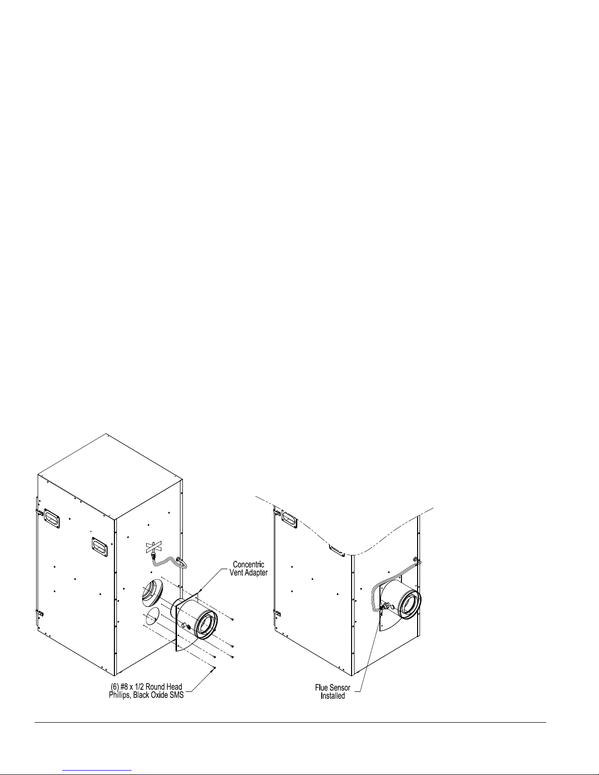
IV. Venting E. Concentric Polypropylene Venting (continued)
d. Flue temperature sensor, factory attached to the
boiler wiring harness, is secured to the left boiler
jacket panel with tape.
e. Remove the tape and push the sensor rubber plug
into Concentric Vent Collar sensor port until the
plug is securely engaged. See Figure 18.
The installation of the Concentric Vent Collar is now
completed.
3. System Assembly
a. Plan venting system to avoid possible contact with
plumbing or electrical wires. Start at vent connector
at boiler and work towards vent termination.
b. Do not exceed maximum Concentric vent length.
Refer to Table 14.
c. If additional concentric vent piping is needed:
i. Concentric Vent Cut-To-Length Extension
pipes, identied in Table 15 CAN BE CUT
to required length when used as an extension.
These pipes have plain male end and beaded
female end. Always cut the pipe from plain
male end. See Figure 19 ‘Cut-To-Length
Extension (Cuttable)”.
ii. The remaining Concentric Vent Fixed
Extensions shown in Table 15 CANNOT BE
CUT. These pipes have beaded male and beaded
female ends. See Figure 20 “Fixed Extension
(Non-Cuttable)’.
d. To cut the Concentric Vent Straight pipe to required
length refer to Figure 21 “Cutting Straight Pipe”
and the following procedure:
i. Determine the required length of the outer
pipe. When doing this allow an additional 1”
of length for insertion into the female end of
the adjoining pipe. Mark the cut line on the
outer pipe.
ii. Remove the plastic inner pipe by pulling it out
from the female end.
iii. Cut the OUTER PIPE ONLY at the point
marked in Step (a) using aviation shears, a
hacksaw, or an abrasive wheel cutter. Be
careful to cut the pipe square. De-burr the cut
end with a le or emery cloth.
iv. Make an insertion mark 1” from the male end
of the outer pipe.
v. Cut the plastic inner pipe so that it will protrude
3/8” beyond the male end of the outer pipe when
reinstalled in the outer pipe. Use a ne tooth
hacksaw or a PVC saw to cut the plastic pipe
and be careful to cut the pipe square. De-burr
the cut edge of the plastic pipe with a le, razor
blade or ne sandpaper.
vi. Reinstall the inner pipe.
e. To join Concentric Vent Pipe refer to Figure 22
“Joining Cuttable Pipe” and Figure 23 “Joining
Non-Cuttable Pipe” and follow the procedure below:
i. Start assembly of the vent system at the boiler.
Lubricate the brown gasket in the boiler vent
collar with a few drops of water.
ii. Push the male end of the rst tting into the
boiler collar until it bottoms out. The male
end of cuttable sections should go 1” into the
collar until the insertion mark (made in Step 4
above) is covered. On other ttings, the bead
on the male pipe will be bottom out on the
collar (see Figure 22).
40 103448-02 - 6/13
Figure 18: Field Installation of Boiler
Concentric Vent Collar
Page 41
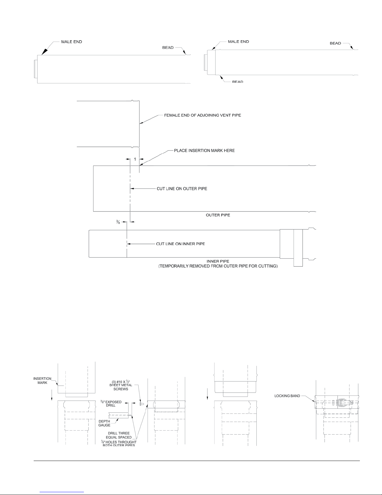
IV. Venting E. Concentric Polypropylene Venting (continued)
Figure 19: Cut-To-Length Extension (Cuttable)
Figure 20: Fixed Extension (Non-Cuttable)
Figure 21: Cutting Straight Pipe
iii. The male end of cuttable ttings must be held
to the collar with three (3) #10 x 1/2” sheet
metal screws. Drill a 1/8 hole through both
outer pipes to start this screw. Use a drill stop
or other means to ensure that the drill bit
does not penetrate more than 3/8” into the
outer pipe. Do not use a sheet metal screw
longer than 1/2” (see Figure 23).
Figure 22: Joining Cuttable Pipe
iv. Use locking bands (provided with all ttings)
to secure non-cuttable pipe, as well as ttings,
to the boiler collar (see Figure 23).
v. Use the same method to join all remaining vent
components except for the terminal.
Figure 23: Joining Non-Cuttable Pipe
103448-02 - 6/13 41
Page 42
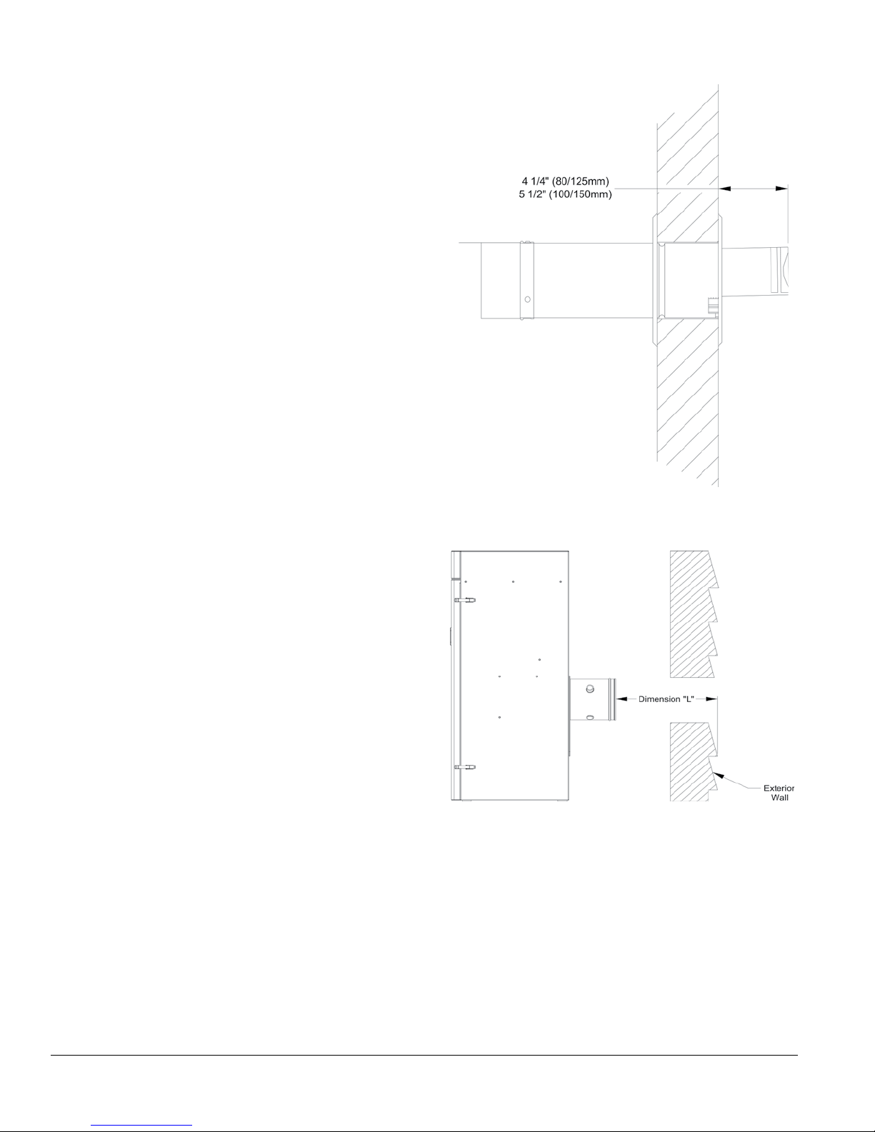
IV. Venting E. Concentric Polypropylene Venting (continued)
4. Horizontal Vent Termination
a. Standard Concentric Termination
Refer to Figure 24.
i. Permitted terminals for horizontal venting:
Horizontal (Wall) Terminal, [80/125 mm
(P/N 101808-01), 100/150 mm
(P/N 101809-01] - see Table 15.
ii. Concentric Vent components supplied with
the boiler are packed inside boiler carton and
include the following:
• Horizontal (Wall) Terminal,
• Horizontal (Wall) Terminal consists of
Straight section having plain male end with
locking band clamp installed; Terminal
Assembly with offset vent termination,
and Outside Wall Plate, both riveted
on the opposite end; overall length is
approximately 28-1/8”.
• Separate Inside Wall Plate
• Two Hardware Bags (each bag contains
four screws and four anchors) to attach vent
terminal Outside Wall Plate to exterior wall
and Inside Wall Plate to interior wall.
iii. For horizontal (sidewall) installation, the
Horizontal (Wall) Terminal will extend past
outer wall surface by 4¼” (80/125 mm) or
5½” (100/150 mm). See Figure 24 “Horizontal
Concentric Venting”.
iv. Install the Horizontal (Wall) Terminal:
• Cut a 5½” diameter hole through the exterior
wall opening (for 80/125 mm concentric
vent) or 6½” (for 100/150 mm) at the planned
location of the horizontal terminal.
• Measure dimension “L” from exterior wall
outer surface to the end of the last tting.
See Figure 25 ‘Dimension “L”’.
• When factory Horizontal (Wall) Terminal
needs to be shortened, measure dimension
“L” plus 1¼” from inside of the attached
Outside Wall Plate and mark the Horizontal
(Wall) Terminal outer pipe. To achieve a
square cut of the outer pipe, place several
marks around the outer pipe to establish a cut
line. See Figure 26 ‘ Cutting Vent Terminal
Pipe’.
• Carefully cut the outer pipe at the marked
line using aviation shears, a hacksaw etc.
Ensure the pipe is cut square and cut end is
de-burred.
• Mark the end of the Horizontal (Wall)
Terminal inner polypropylene vent pipe to
extend 3/8” past the cut end of the outer pipe.
Figure 24: Horizontal Concentric Venting
Figure 25: Dimension “L”
To achieve a square cut of the inner pipe,
place several marks around the inner pipe
to establish a cut line.
• Cut off the marked end of inner polypropylene
vent pipe with a ne tooth blade hacksaw
etc. and de-burr. See Figure 26 “Cutting Vent
Terminal Pipe.
This pipe can be removed from the terminal
to ease cutting, if desired.
42 103448-02 - 6/13
Page 43
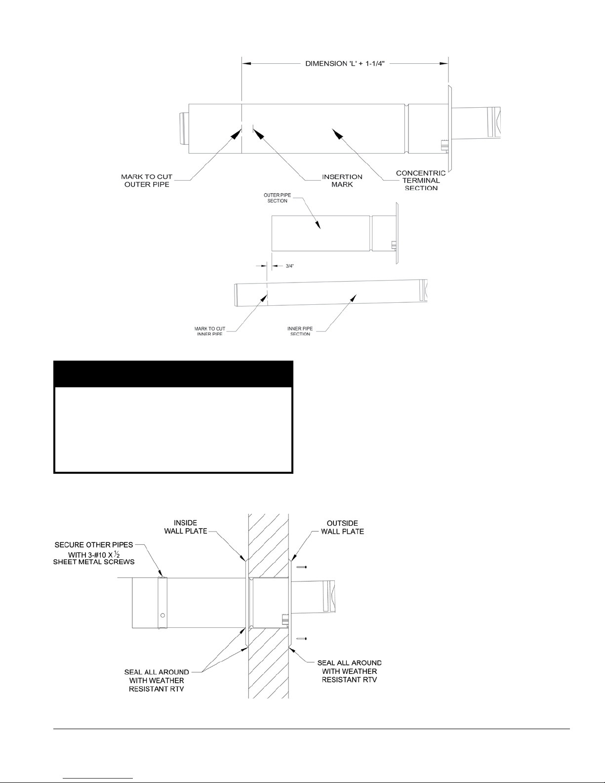
IV. Venting E. Concentric Polypropylene Venting (continued)
Figure 26: Cutting Vent Terminal Pipe
CAUTION
Exterior wall surface must be reasonably at to
attach the Outside Wall Plate. When exterior wall
surface is not at (covered with vinyl or wood
shingle siding etc.) the siding must be removed,
and a at surface build up ash or above siding
exterior surface to secure/seal the terminal
Outside Wall Plate.
• Install the supplied Inside Wall Plate onto the
shortened Horizontal (Wall) Terminal interior
end and move the plate to cover interior wall
cut opening. Secure the plate with provided
fasteners, then, apply the sealant around plate
sides to seal it to interior wall (refer to Figure
27).
• Lubricate the brown gasket inside boiler
concentric vent collar or the last section of
the vent pipe with small amount of water.
• Ensure that inner pipe of the terminal is evenly
engaged into the gasket all around, then
push the termination male end inside boiler
concentric vent collar or the last section of
the vent pipe, until the mark (see Step v) is
no longer visible.
• Re-install locking band clamp onto the joint
to secure the terminal to the collar or the last
section of the vent pipe.
Figure 27: Completing Horizontal (Wall Terminal Installation)
103448-02 - 6/13 43
Page 44
IV. Venting E. Concentric Polypropylene Venting (continued)
Vertical Vent Termination
5.
a. Standard Concentric Termination
Refer to Figures 28 thru 32.
i. In addition to the vertical terminal, either a
Flat Roof Flashing or Sloped Roof Flashing
is required for this installation. Refer to Table
15 ‘Concentric Vent Components’ for details.
• Determine the centerline of the terminal
location on the roof. For at roof, cut 5½”
diameter hole (80/125 mm concentric vent
size) or 6½” (100/150 mm) for the terminal.
For sloped roof, cut a hole in the roof large
enough for the terminal to pass through the
roof while remaining plumb.
b. Optional Concentric Chimney Chase Installation
Refer to Figure 32.
CAUTION
If the boiler is located directly under the hole,
cover it while cutting the hole to prevent debris
from falling onto boiler.
• Install the roof flashing using standard
practice on the roong system of the structure.
• If not already done, assemble the venting
system inside the building. The last section
of pipe needs to be on the same center line
as the terminal and within 19-1/4” of the top
edge of the roof ashing.
• Measure distance “H” from the top edge of
the storm collar to the end of the last tting
as shown in Figure 29.
• Add 1” to distance “H”. Carefully mark this
length on the pipe as shown in Figure 30.
• Cut the outer pipe only at the point marked
in Step (e) using aviation shears, a hacksaw,
or an abrasive wheel cutter. Be careful to cut
the pipe square. De-burr the cut end with a
le or emery cloth.
• Place a mark on the plastic inner pipe 3/8”
beyond the end of the outer pipe (Figure 30).
Use a ne tooth hacksaw to cut the plastic
pipe and be careful to cut the pipe square.
De-burr the cut edge of the plastic pipe with
a le or emery cloth.
• Make a mark on the terminal section 1” from
the cut end of the outer pipe as shown in
Figure 30.
• Slip the terminal section through the roof
from the outside. Push into the last section
of vent pipe until the mark made in Step (h)
is not longer visible. Secure the terminal to
the last piece of pipe with three #10 x 1/2”
sheet metal screws. Drill a 1/8” hole through
both outer pipes to start these screws. Use a
drill stop or other means to ensure that
the drill bit does not penetrate more than
44 103448-02 - 6/13
F. Removing the Existing Boiler
For installations not involving the replacement of an
existing boiler, proceed to Step F.
When an existing boiler is removed from a common venting
system, the common venting system is likely to be too large
for proper venting of the remaining appliances. At the time
of removal of an existing boiler, the following steps shall
be followed with each appliance remaining connected to
the common venting system placed in operation, while
the other appliances remaining connected to the common
venting system are not in operation:
1. Seal any unused openings in the common venting
system.
2. Visually inspect the venting system for proper size and
horizontal pitch and determine there is no blockage or
restriction, leakage, corrosion, and other deciencies
which could cause an unsafe condition.
3. Insofar as is practical, close all building doors and
windows and all doors between the space in which the
appliances remaining connected to the common venting
system are located and other spaces of the building.
Turn on clothes dryers and any appliance not connected
to the common venting system. Turn on any exhaust
fans, such as range-hoods and bathroom exhausts, so
they will operate at maxi mum speed. Do not operate
a summer exhaust fan. Close replace dampers.
3/8” into the outer pipe. Do not use a sheet
metal screw longer than 1/2”.
• Secure the terminal section to the inside of
the roof structure using the mounting bracket
provided with the terminal (Figure 31).
i. A vertical concentric vent system can be
installed in an UNUSED masonry chimney.
• The Chimney chase Support Elbow with
attached Mounting Bracket is used at the base
of the chimney. Refer to Table 15 ‘Concentric
Vent Components’ for details. Slip the elbow
over the M10 x 35 screw in the support
bracket. Determine the desired vertical
location of the support elbow in the chimney
and mark the location of the pin, positioned
on the back of the support bracket, onto the
chimney rear wall. Drill a 7/16” diameter x
3-1/2” deep hole in the marked location, then,
insert the back bracket pin into the hole. The
front of the elbow mounting bracket should
be supported either by bottom of the opening
into chimney or installer supplied spacer.
• Construct a weather-tight at roof to cover
the top of the old chimney. Install the vertical
terminal through this roof using the at roof
ashing.
Page 45
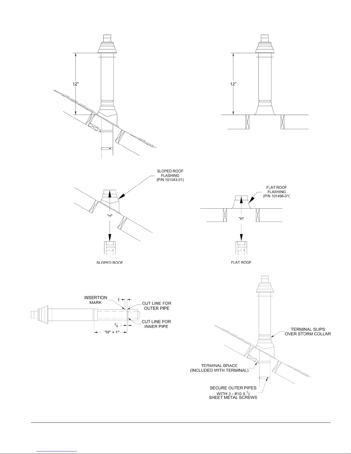
IV. Venting F. Removing the Existing Boiler (continued)
Figure 28: Vertical Concentric Vent Installation
Figure 29: Dimension "H"
Figure 30: Cutting Vertical Terminal
Figure 31: Completing Vertical Terminal Installation
103448-02 - 6/13 45
Page 46
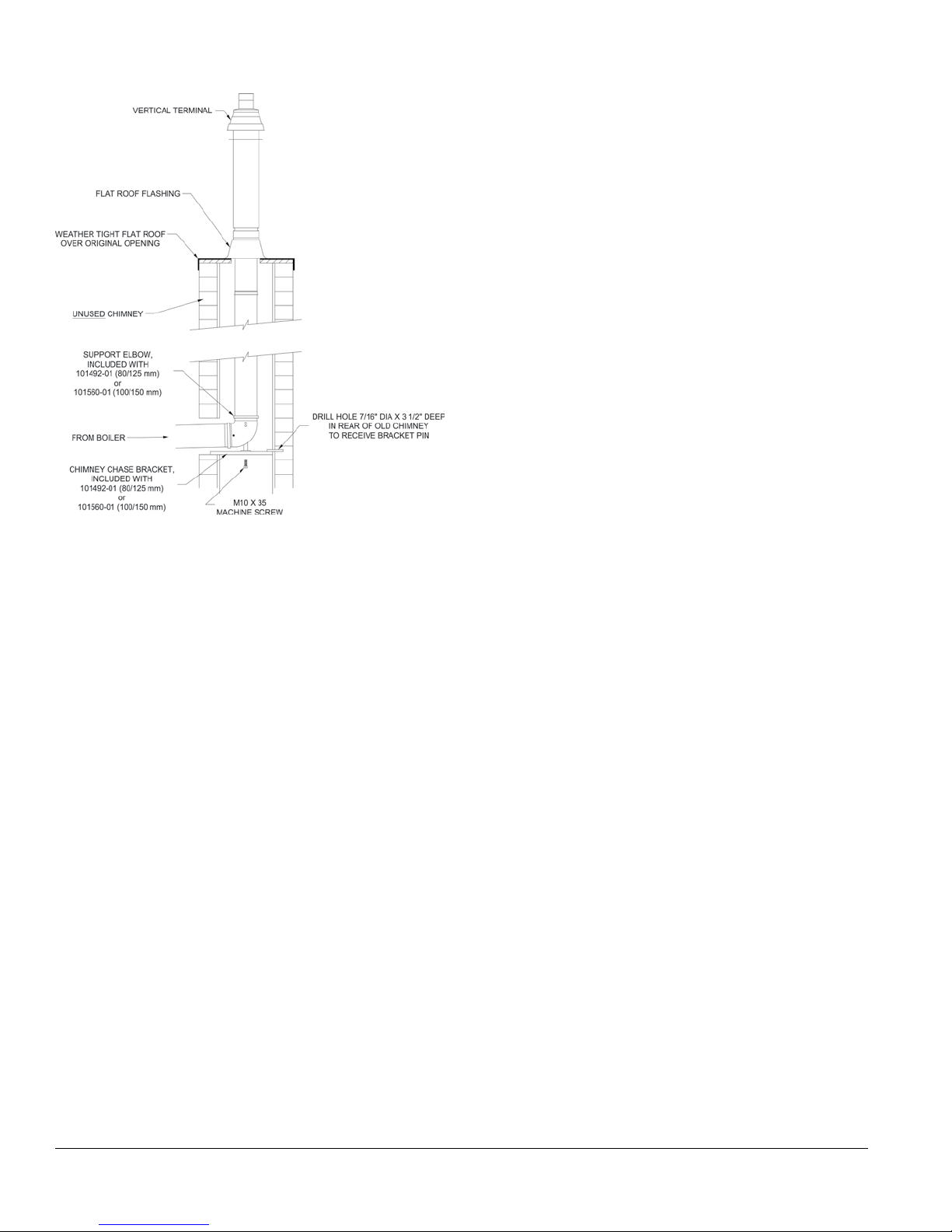
IV. Venting F. Removing the Existing Boiler (continued)
Figure 32: Chimney Chase Installation
4. Place in operation the appliance being inspected.
Follow the Lighting (or Operating) Instructions. Adjust
thermo stat so appliance will operate continuously.
5. Test for spillage at the draft hood relief opening after
ve (5) minutes of main burner operation. Use the
ame of a match or candle, or smoke from a cigarette,
cigar or pipe.
6. After it has been determined that each appliance
remain ing connected to the common venting system
properly vents when tested as outlined above, return
doors, win dows, exhaust fans, replace dampers and
any other gas burning appliance to their previous
conditions of use.
7. Any improper operation of the common venting system
should be corrected so the installation conforms with
the National Fuel Gas Code, NFPA 54/ANSI Z223.1.
When resizing any portion of the common venting
system, the common venting system should be resized
to approach the minimum size as determined using the
appropriate tables in Part II in the National Fuel Gas
Code, NFPA 54/ANSI Z223.1.
Au moment du retrait d’une chaudière existante,
les mesures suivantes doivent être prises pour
chaque appareil toujours raccordé au système
d’evacuation commun et qui fonctionne alors que
d’autres appareils toujours raccordés au système
d’évacuation ne fonctionnent pas:
1. Sceller toutes les ouvertures non utilisées du
système d’évacuation.
2. Inspecter de facon visuelle le système d’évcuation
pour déterminer la grosseur et l’inclinaison
horizontale qui conviennent et s’assurer que le
système est exempt d’obstruction, d’étranglement,
de fuite, de corrosion et autres défaillances qui
pourraient présenter des risques.
3. Dans la mesure du possible, fermer toutes les
portes et les fenêtres du bâtiment et toutes les
portes entre l’espace où les appareils toujours
raccordés au système d’évacuation sont installés
et les autres espaces du bâtiment. Mettre en
marche les sécheuses, tous les appareils non
raccordés au système d’évacuation commun
et tous les ventilateurs d’extraction comme les
hottes de cuisinière et les ventilateurs des salles de
bain. S’assurer que ces ventilateurs fonctionnent
à la vitesse maximale. Ne pas faire fonctionner
les ventilateurs d’été. Fermer les registres des
cheminées.
4. Mettre l’appareil inspecté en marche. Suivre les
instructions d’allumage. Régler le thermostat de
facon que l’appareil fonctionne de facon continue.
5. Faire fonctionner le brùleur principal pendant 5
min ensuite, déterminer si le coupe-tirage déborde
à l’ouverture de décharge. Utiliser la amme d’une
allumette ou d’une chandelle ou la fumée d’une
cigarette, d’un cigare ou d’une pipe.
6. Une fois qu’il a été déterminé, selon la méthode
indiquée ci-dessus, que chaque appareil raccordé
au système d’évacuation est mis à l’air libre de
facon adéquate. Remettre les portes et les fenêtres,
les ventilateurs, les registres de cheminées et les
appareils au gaz à leur position originale.
7. Tout mauvais fonctionnement du système
d’évacuation commun devrat être corrigé de
facon que l’installation soit conforme au National
Fuel Gas Code, ANSI Z223.1 et (ou) aux codes
d’installation CAN/CSA-B149.1. Si la grosseur
d’une section du système d’évacuation doit être
modiée, le système devrait être modié pour
respecter les valeurs minimales des tableaux
pertinents de l’appendice F du National Fuel Gas
Code, ANSI Z223.1 et (ou) des codes d’installation
CAN/CSA-B149.1.
G. Multiple Boiler Installation Venting
1. CPVC/PVC or Polypropylene Venting
a. Multiple Boiler CPVC/PVC or polypropylene
direct venting is shown in Figure 33.
b. Each individual module (boiler) must have own
vent pipe and vent terminal. Refer to Section IV
“Venting” of this manual for individual module
(boiler) venting guidelines and options.
46 103448-02 - 6/13
Page 47
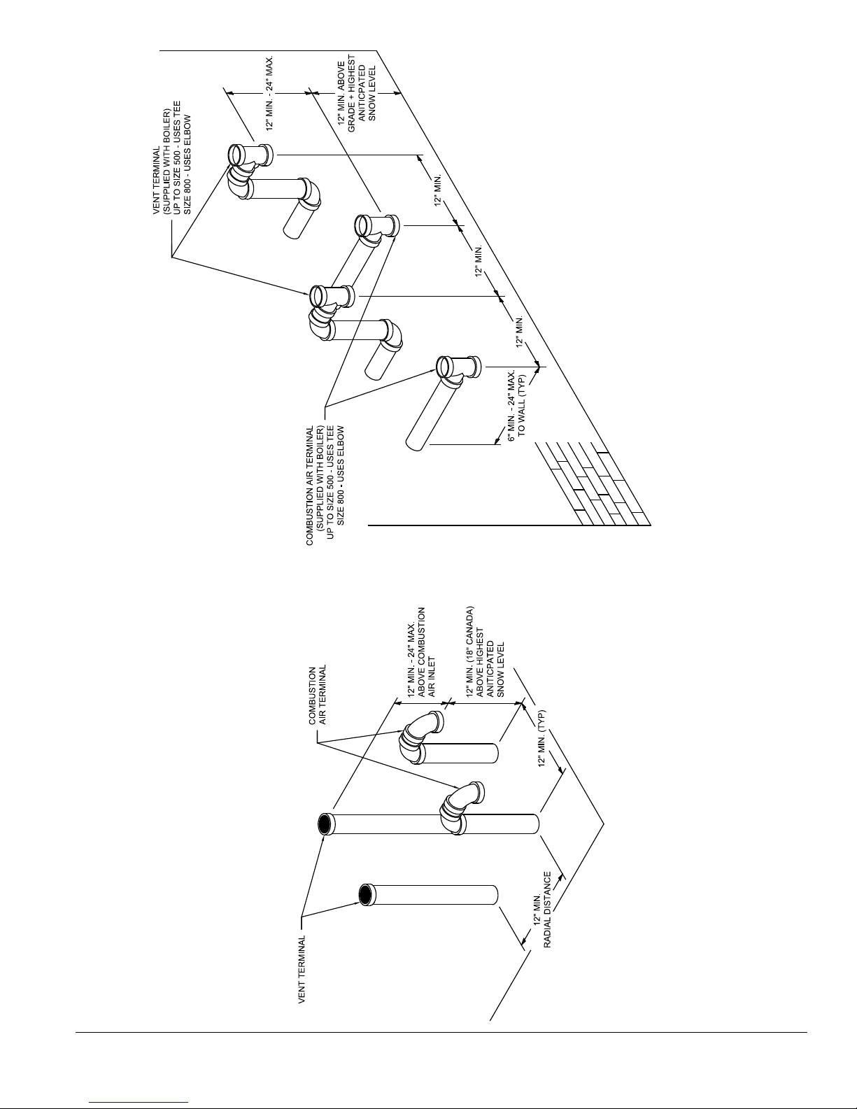
IV. Venting G. Multiple Boiler Installation Venting (continued)
103448-02 - 6/13 47
Figure 33: Multiple Boiler Direct Vent Termination
Page 48
IV. Venting G. Multiple Boiler Installation Venting (continued)
WARNING
No common manifolded venting (vent piping and
vent terminals) is permitted.
c. The individual module (boiler) maximum vent
length - see Section IV, “Venting”, Table 8.
d. For sidewall venting the minimum horizontal
distance between any adjacent individual module
(boiler) vent terminations is twelve (12) inches.
Additional horizontal spacing between any adjacent
individual module (boiler) vent terminations as well
as extending the distance from building surfaces
to vent termination end are recommended to avoid
frost damage to building surfaces where vent
terminations are placed.
CAUTION
Installing multiple individual module (boiler) vent
terminations too close together may result in
combustion product water vapor condensation
on building surfaces, where vent termination are
placed, and subsequent frost damage. To avoid/
minimize frost damage, extend the distance from
building surfaces to vent termination end and
increase the horizontal distance between adjacent
vent terminations.
e. Individual module (boiler) sidewall vent
terminals must be placed at least twelve (12)
inches above the ground plus the expected snow
accumulation.
f. Multiple individual module vertical vent pipes
may be piped through a common conduit or
chase so that one roof penetration may be made.
The minimum horizontal distance between any
adjacent individual module (boiler) roof vent
terminations is one (1) foot.
2. PVC Pipe Air Intake Piping
a. Multiple Boiler PVC air intake piping is shown
in Figure 33.
b. Each individual module (boiler) must have own
combustion air intake pipe and combustion air
intake terminal. Refer to Section IV “Venting”
of this manual for individual module (boiler)
combustion air intake guidelines and options.
c. The individual module (boiler) maximum
combustion air intake pipe length - see Section
IV, “Venting”, Table 8.
d. If possible, locate each individual module
(boiler) both combustion air intake termination
and vent termination on the same sidewall, to
prevent nuisance boiler shutdowns.
However, if same sidewall placement is
problematic, an individual module (boiler) may
be installed using vertical venting and sidewall
combustion air intake termination (or, vice versa)
3. Concentric Combination Venting/Combustion
Air Intake Piping
a. Concentric Combustion Venting and air intake is
shown in Figure 34.
b. Each individual module (boiler) must have
own concentric vent pipe and vent termination.
Follow Section IV “Venting” of this manual for
individual module (boiler) concentric venting
guidelines.
WARNING
No common manifolded concentric venting is
permitted.
c. The individual module (boiler) maximum
concentric vent length - see Section IV,
“Venting”, Table 8.
d. For sidewall venting any adjacent individual
module (boiler) concentric vent terminals must
be spaced no closer than 12 inches horizontally
and three (3) feet vertically from each other to
prevent combustion air contamination.
Additional horizontal spacing between any
adjacent individual module (boiler) concentric
vent terminations and increased distance from
building surfaces to concentric vent termination
end are recommended to avoid frost damage to
building surfaces where vent terminations are
placed.
e. Individual module (boiler) sidewall concentric
vent terminals must be placed at least twelve
(12) inches above the ground plus the expected
snow accumulation.
f. For vertical through the roof venting any
adjacent individual module (boiler) vertical
vent terminals, if level with each other, must be
spaced no closer than 12 inches horizontally.
If vertical vent terminals cannot end in one
plane, they must be spaced no closer than three
(3) feet horizontally.
g. Chimney chase concentric venting is permitted
for modules, when stackable, providing
concentric vertical (roof) vent terminals, if level
with each other, are spaced no closer then 12
inches horizontally.
If vertical vent terminals cannot end in one
plane, they must be spaced no closer then three
(3) feet horizontally.
48 103448-02 - 6/13
Page 49
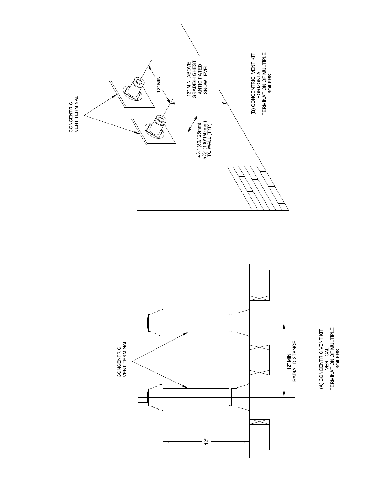
IV. Venting G. Multiple Boiler installation Venting (continued)
103448-02 - 6/13 49
Figure 34: Multiple Boiler Concentric Vent Termination
Page 50
IV. Venting G. Multiple Boiler Installation Venting (continued)
h. When individual modules (boilers) are installed
in the same horizontal plane, chimney chase
vertical concentric venting is permitted provided:
V. Condensate Disposal
A. Condensate Trap and Drain Line.
1. All condensate, which forms in the boiler or vent
system, collects in the sump under heat exchanger
and leaves the boiler through factory installed
condensate trap.
2. The trap allows condensate to drain from sump
while retaining ue gases in the boiler. The trap
has factory installed overow switch, which shuts
down the boiler in the event the drain line becomes
obstructed, preventing proper condensate removal.
Refer to Section XI “Service and Maintenance” for
condensate trap and condensate overow switch
removal and replacement procedure, if required.
3. Note the following when disposing of the
condensate:
a. Condensate is slightly acidic, typical pH around
3.5 - 4.5. Do not use metallic pipe or ttings in
the condensate drain line. Do not route the drain
line through areas that could be damaged by
leaking condensate.
b. Do not route or terminate the condensate drain
line in areas subject to freezing temperatures.
c. If the point of condensate disposal is above the
trap, a condensate pump is required to move
the condensate to the drain. Select a condensate
pump approved for use with condensing boilers.
If overow from the pump would result in
property damage, select a pump with an overow
switch. Wire this switch in series with installer
provided external high limit, to shut off the
boiler, and, if desired, in series with installersupplied alarm, to trigger an alarm in the event
of overow.
d. Do not attempt to substitute another trap for one
provided with the boiler.
i. Sufcient inside space available at the base
of the chimney to install multiple chimney
chase brackets and support elbows.
ii. Spacing between adjacent vertical vent
terminals is in accordance with Item ‘g’
above.
e. In order for boiler to work properly, the boiler
must be leveled during installation.
4. The condensate trap stub is located at boiler left
side, below inlet and outlet water pipe connections.
Refer to Figures 1A thru 1C.
5. Condensate trap must be lled up with water,
prior to boiler start-up and before connecting
any condensate line to the boiler, to insure
combustion products cannot escape from
operating boiler. To ll the trap, inject water in the
amount of 1 cup (8 uid ounces) through condensate
trap stub opening. Do not overll the trap.
6. If any additional condensate drain line is needed,
construct the extension from PVC or CPVC
Schedule 40 pipe. The factory supplied ¾” x 5-5/8”
long PVC coupling, located in the Part Carton, must
be used to connect drain line to the condensate trap
stub. Do not over tighten coupling compression nuts
when connecting drain line and condensate trap
stub.
WARNING
Failure to install the condensate trap and
condensate drain in accordance with the above
instructions could cause ue gas to enter the
building, resulting in personal injury or death.
CAUTION
Boiler condensate is corrosive. Route
condensate drain line in a manner such
that any condensate leakage will not cause
property damage.
Some jurisdictions may require that
condensate be neutralized prior to disposal.
50 103448-02 - 6/13
Page 51
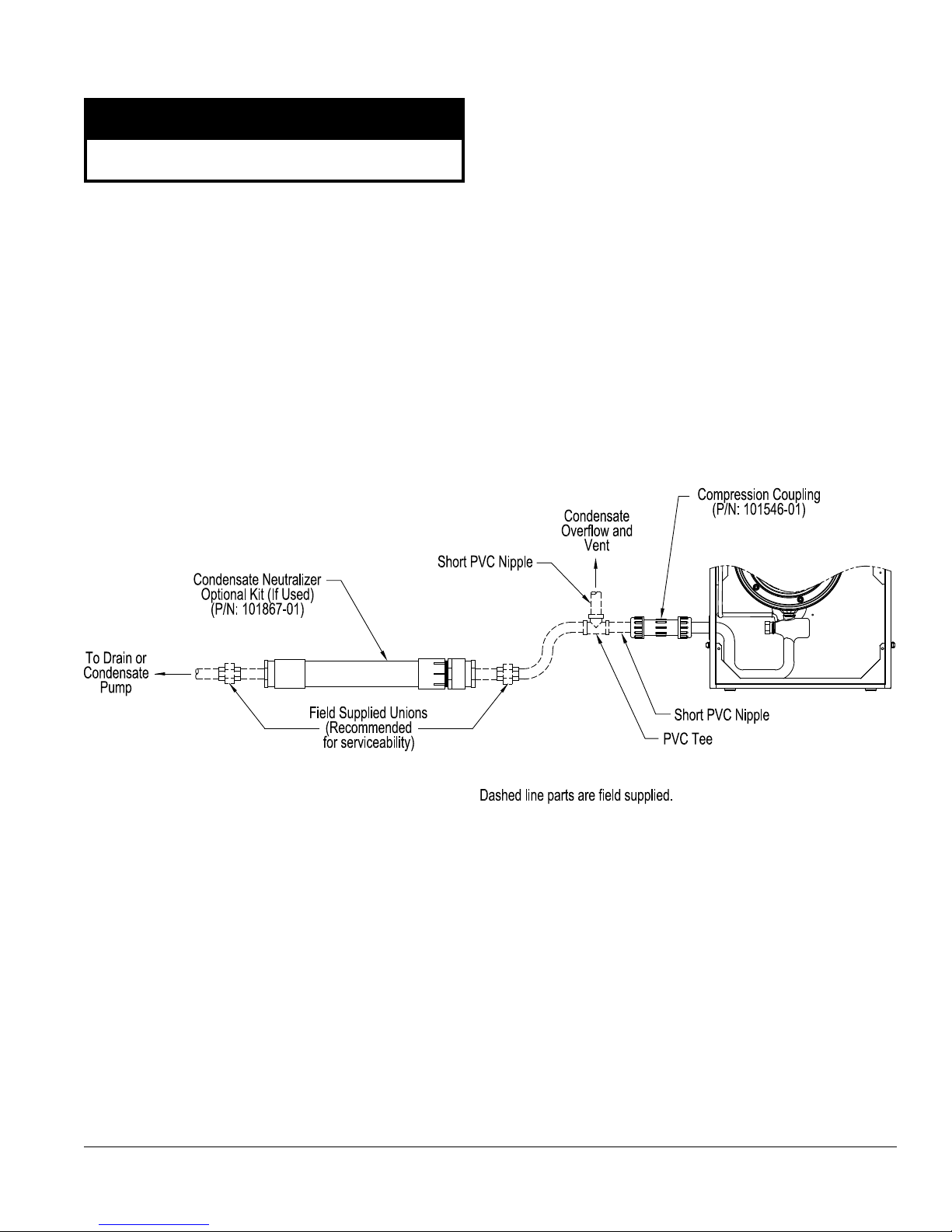
V. Condensate Disposal (continued)
NOTICE
Use materials approved by the authority having
jurisdiction.
B. Condensate Neutralizer Installation
1. Some jurisdictions may require that the condensate
be neutralized before being disposed of. Follow
local codes pertaining to condensate disposal.
2. A Condensate Neutralizer Kit (P/N 101867-01)
is available as optional equipment. Follow local
codes and instructions enclosed with the kit for
Condensate Neutralizer installation.
3. Limestone chips will get coated by neutral salts
(product of chemical reaction between limestone
and acidic condensate) and lose neutralizing
effectiveness over time. Therefore, periodic
condensate neutralizer maintenance and limestone
chip replacement must be performed. A pH test or
acid test kits are available from HVAC/plumbing
distributors and should be used to measure
condensate acidity before/after neutralizer thus
indicating a need for service and chip replacement.
103448-02 - 6/13 51
Figure 35: Condensate Trap and Drain Line
Page 52
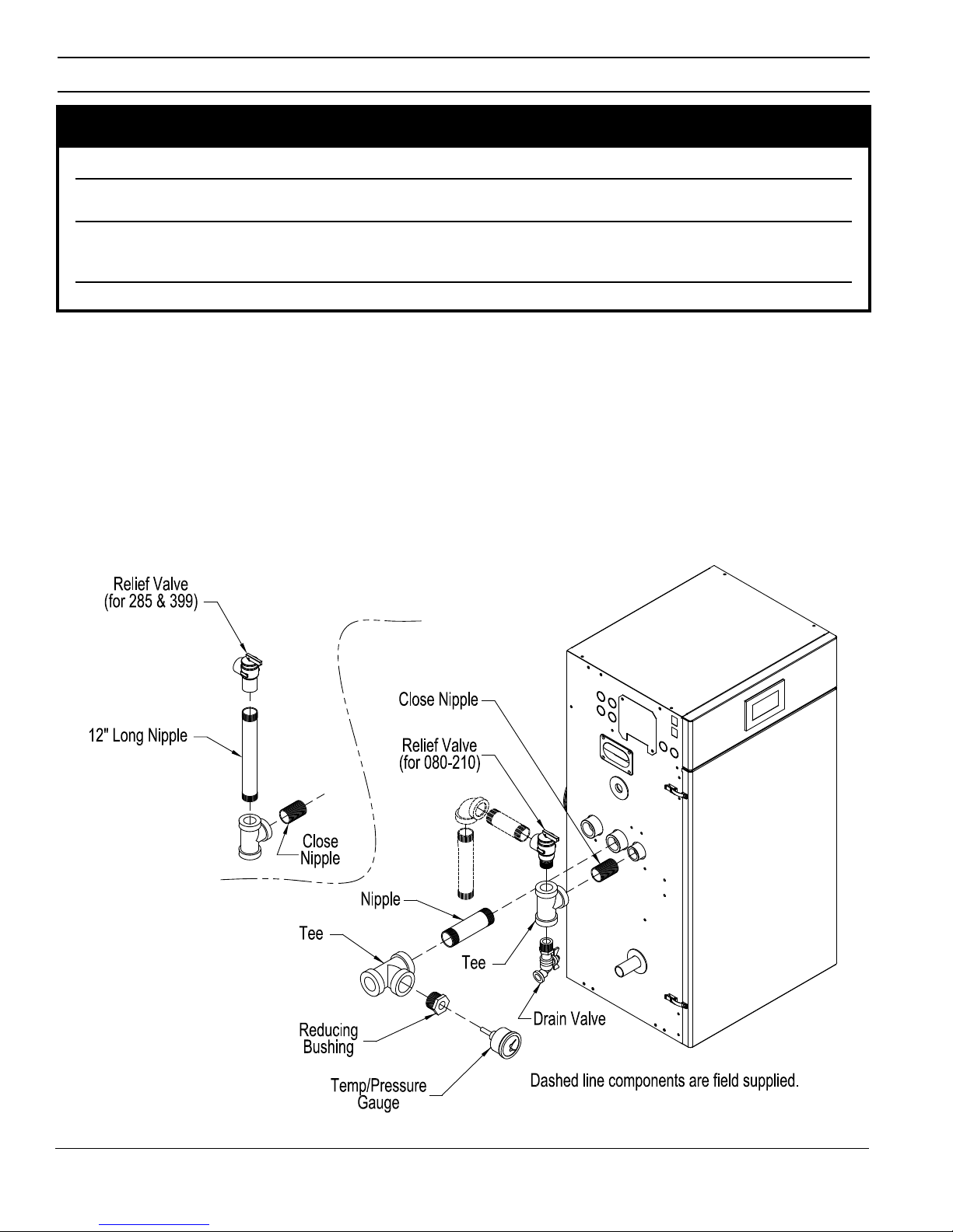
VI. Water Piping and Trim
WARNING
Failure to properly pipe boiler may result in improper operation and damage to boiler or structure.
Install boiler so that the gas ignition system components are protected from water (dripping, spraying,
rain, etc.) during boiler operation and service (circulator replacement, etc.).
Oxygen contamination of boiler water will cause corrosion of iron and steel boiler components, and can
lead to boiler failure. U.S. Boiler Company’s Standard Warranty does not cover problems caused by
oxygen contamination of boiler water or scale (lime) build-up caused by frequent addition of water.
Do not ll boiler with softened water to prevent chloride contamination.
A. Installation of Factory Supplied Piping and Trim
Components
Alpine (ALP) boilers have factory supplied Miscellaneous
Part Carton (P/N 102942-01 – ALP080B thru ALP210B;
102942-02 or 103676-01 – ALP285B; 102942-03 –
ALP399), which includes supply piping components,
gas piping components, Temperature & Pressure Gauge,
Pressure Relief Valve and Drain Valve. See Figure 30
“ Factory Supplied Piping and Trim Installation”.
Install these components prior to connecting boiler to
system piping as follows:
1. Relief Valve Piping, ALP080B thru ALP210B Boiler
Models
a. Locate and remove ¾” NPT x close black nipple,
¾” NPT black tee, ¾” MPT x ¾” FPT Pressure
Relief Valve, ¾” NPT Drain Valve.
b. Install close nipple into tee branch, then, screw
the assembly into boiler left side front ¾” tapping
making sure tee run outlets are in vertical plane
and parallel to boiler side.
c. Mount ¾” MPT x ¾” FPT Pressure Relief Valve
into the tee top outlet.
d. Install Drain Valve into the tee bottom outlet.
Figure 36: Factory Supplied Piping and Trim Installation
52 103448-02 - 6/13
Page 53
VI. Water Piping and Trim A. Factory Supplied Piping and Trim (continued)
2. Relief Valve Piping, ALP285B and ALP399 Boiler
Models
a. Locate and remove (1) ¾” NPT x close black nipple,
(1) ¾” NPT x 12” black nipple, ¾” NPT black tee,
¾” FPT x ¾” FPT Pressure Relief Valve, ¾” NPT
Drain Valve.
b. Install close nipple into tee branch, then, screw
the assembly into boiler left side front ¾” tapping
making sure tee run outlets are in vertical plane
and parallel to boiler side.
c. Install the ¾” NPT x 12” black nipple into tee run
top outlet.
d. Mount ¾” FPT x ¾” FPT Pressure Relief Valve
onto the 12” nipple.
e. Install Drain Valve into the tee bottom outlet.
3. Temperature /Pressure Gauge Piping, ALP080B thru
ALP210B Boiler Models
a. Locate and remove 1” NPT x 4” long black nipple,
1” x 1” x 1” NPT black tee, 1” x ¼” NPT black
reducing bushing and Temperature & Pressure
Gauge.
b. Mount the nipple into 1” boiler supply tapping (see
Figures 1A and 1B), then, install the tee onto the
nipple, making sure 1” branch outlet is in horizontal
plane and facing the boiler front.
c. Install 1” x ¼” NPT black reducing bushing into
the tee branch, then, put in Temperature & Pressure
Gauge.
4. Temperature /Pressure Gauge Piping, ALP285B Boiler
Model
a. Locate and remove 1¼” NPT x 2” long black
nipple, 1¼” x 1¼” x ¾” NPT black tee, ¾” x ¼”
NPT black reducing bushing and Temperature &
Pressure Gauge.
b. Mount the nipple into 1¼” boiler supply tapping
(see Figures 1B and 1C), then, install the tee onto
the nipple, making sure ¾” branch outlet is in
horizontal plane and facing the boiler front.
c. Install ¾” x ¼” NPT black reducing bushing into
the tee branch, then, put in Temperature & Pressure
Gauge.
5. Temperature /Pressure Gauge Piping, ALP399 Boiler
Model
a. Locate and remove 1½” NPT x 2” long black
nipple, 1½” x 1½” x ¾” NPT black tee, ¾” x ¼”
NPT black reducing bushing and Temperature &
Pressure Gauge.
b. Mount the nipple into 1½” boiler supply tapping
(see Figures 1B and 1D), then, install the tee onto
the nipple, making sure ¾” branch outlet is in
horizontal plane and facing the boiler front.
c. Install ¾” x ¼” NPT black reducing bushing into
the tee branch, then, put in Temperature & Pressure
Gauge.
B. Piping System To Be Employed.
Alpine (ALP) boilers are designed to operate in a closed
loop pressurized system. Minimum pressure in the
boiler must be 12 PSI. Proper operation of the Alpine
(ALP) boiler requires that the water ow through the
boiler remain within the limits shown in Table 16, any
time the boiler is ring.
NOTICE
Failure to maintain the ow through boiler within
specied limits could result in erratic operation or
premature boiler failure.
1. Near boiler piping must isolate ALP boiler from
system piping via closely spaced tees to insure
specied ow range through boiler any time the
boiler is ring:
a. The ow rate through the isolated near-boiler
loop is maintained by factory recommended and
installer supplied boiler circulator.
b. The ow rate through the isolated near-boiler
loop is completely independent of the ow rate
through the heating system loop(s).
c. The ow rate through the heating system loop(s)
is controlled by installer sized/provided system
loop circulator(s).
d. This piping arrangement can be used either for
space heating-only applications or space heating
with indirect water heater(s) applications.
i. Space heating only - refer to Table 17 and
Figure 37 “Near Boiler Piping - Heating
Only” as applicable.
ii. Space heating plus indirect water
heater(s) - refer to Table 17 and Figure 38
“Near Boiler Piping - Heating Plus Indirect
Water Heater” as applicable.
NOTICE
Where it is not possible to install a separate
boiler loop, the system circulator must be
sized to ensure that the ow through boiler
stays within the dened parameters to prevent
overheating when the boiler is red at it’s full
rated input. Install a ow meter to measure the
ow, or re the boiler at full rate and ensure the
boiler DT does not exceed 35°F.
103448-02 - 6/13 53
Page 54
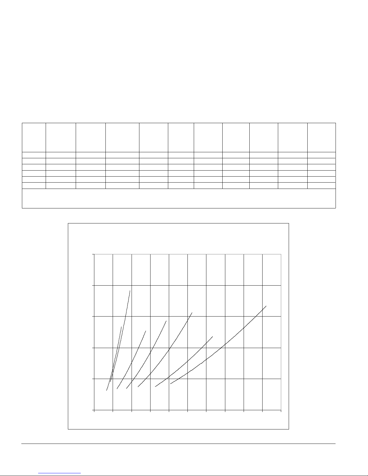
VI. Water Piping and Trim B. Piping System To Be Employed (continued)
2. Direct connection of Alpine (ALP) boiler to
heating system, similar to a conventional boiler, is
NOT RECOMMENDED because:
a. The ow rate through system must be the same
as through boiler and fall within limits specied
in Table 16.
b. Pressure drop through entire system must be
known, added to pressure drop through boiler,
and, a circulator selected to provide required
ow at total calculated pressure drop.
c. It is often very difcult to accurately calculate
the pressure drop through the system.
d. In replacement installations, it may be nearly
impossible to get an accurate measurement of
piping amount and number of ttings in the
system. If system is zoned, the system ow rate
may drop well below recommended minimum
ow when only a single zone is calling for heat.
Table 16: Flow Range Requirement Through Boiler
Boiler
Model
ALP080B 1 1 4.2 4.8 4.9 6.4 5.8 8.9 7.3 13.4
ALP105B 1 1 5.5 7.0 6.4 9.3 7.7 12.8 9.6 19.1
ALP150B 1 1 7.9 5.2 9.2 6.6 11.0 8.9 13.8 12.7
ALP210B 1 1 11.1 5.4 12.9 7.1 15.5 9.8 19.4 14.4
ALP285B 1¼ 1¼ 15.1 5.9 17.7 7.8 21.2 10.7 26.5 16.0
ALP399 1½ 1½ 21.5 6.1 25.1 7.9 30.2 10.8 37.7 15.9
Notes: Required Flow (GPM) = ** Output (MBH) x 1000/500 x DT
** Output (MBH) - Select Value for specic Boiler Model from Tables 2A or 2B
Using boiler antifreeze will result in higher uid density and may require larger circulators.
Boiler
Supply
Connection,
Inch, FPT
Boiler
Return
Connection,
Inch, FPT
Minimum
Required
Flow (GPM)
@ 35°F DT
Boiler
Head Loss,
Ft.
@ 35°F DT
Required
Flow,
(GPM)
@ 30°F DT
Boiler
Head Loss,
Ft.
@ 30°F DT
Required
Flow,
(GPM)
@ 25°F DT
Boiler
Head Loss,
Ft.
@ 25°F DT
Maximum
Required
Flow (GPM)
@ 20°F DT
Boiler
Head Loss,
@ 20°F DT
Ft.
Alpine Boiler Head Loss vs. Flow
25
20
105
15
10
150
210
285
399
Boiler Head Loss (Feet)
5
80
0
0 5 10 15 20 25 30 35 40 45 50
Flow Rate (GP M)
500
54 103448-02 - 6/13
Page 55

VI. Water Piping and Trim B. Piping System To Be Employed (continued)
3. Alpine boiler models ALP080B thru ALP285B are
factory supplied with circulators, which were sized
for near-boiler piping equivalent length of 50 ft.
and listed temperature differential. See Table 17 for
details.
It is the installer’s responsibility to insure a proper
installation and where applicable, proper circulator
speed setting for the boiler circulator to achieve
a required ow rate. Where near-boiler piping
The 10th digit of the Alpine boiler part number indicates the
brand of boiler circulator included with the boiler. A “T” in
the 10th digit of the part number indicates a Taco circulator;
a “G” indicates a Grundfos circulator.
Example:
Boiler part number: ALP105BW-2T02 indicates Alpine
boiler equipped with Taco Circulator
Boiler part number: ALP105BW-2G02 indicates Alpine
boiler equipped with Grundfos Circulator
exceeds 50 equivalent feet, alternate circulator
selection may be required.
Table 17: Recommended Circulator Models for Alpine (ALP) Boilers Based on Listed Temperature Differential
and 50 ft. Equivalent Length Near-Boiler Piping - Space Heating Circulator
Boiler
Model
ALP080B 1 1 1 1 7.3
ALP105B 1 1 1 1 7.7 14.3
ALP150B 1 1 1 1 11.0 11.7
ALP210B 1 1 1¼ 1¼ 15.5 11.7
ALP285B 1¼ 1¼ 1½ 1½ 21.5 12.3
ALP399 1½ 1½ 2 2 30.2 11.6
Notes:
(1)
(2)
(3)
When selecting Circulators other than recommended, contact Circulator Manufacturer for sizing information.
Boiler Supply
Connection,
Inch, FPT
Temperature Differential = 20°F
Taco Circulators shown are not equipped with internal ow check valve (IFC).
Circulators are not supplied with boiler.
Near-Boiler Piping Size shown is based on 2 to 5.5 Ft/Sec. velocity range to avoid potential noise and pipe erosion.
Boiler
Return
Connection,
Inch, FPT
Near-Boiler
Piping
Supply Pipe
Size, Inch
Near-Boiler
Piping
Return Pipe
Size, Inch
Flow, GPM
@ 25°F
Temp.
Differential
(1)
Combined
Boiler &
Piping Loop
Head Loss, Ft.
14.7
Recommended
Circulator
Make & Model
Taco 0015 (Speed 3)
Grundfos UPS
15-58 FRC (Speed 2)
Taco 0015 (Speed 3)
Grundfos UPS
26-99 FC (Speed 1)
Taco 0015 (Speed 3)
Grundfos UP
26-99 FC (Speed 2)
Taco 0014
Grundfos UP
26-99 FC (Speed 2)
Taco 0011
Grundfos UP
26-99 FC (Speed 3)
Taco 2400-20
Grundfos UPS
26-150 F/SF (Speed 2)
(2)
(2)
(2) (3)
(2)
(2)
(2)
C. Standard Installation Requirements
Observe the following guidelines when making the
actual installation of the boiler piping:
1. Safety Relief Valve (Required) - The relief valve is
packaged loose with boiler and must be installed in
the location shown in Figure 36 “Factory Supplied
Piping and Trim Installation”. The relief valve must be
installed with spindle in vertical position. Installation
of the relief valve must comply with ASME Boiler and
Pressure Vessel Code, Section IV. The standard factory
103448-02 - 6/13 55
shipped relief valve is rated for 30 PSI maximum
working pressure for ALP080B thru ALP285B and
50 PSI for ALP399. Optional 50 PSI, 80 PSI and 100
PSI maximum working pressure rated relief valves are
available. If the valve is to be replaced, the replacement
valve must have a relief capacity equal or exceeding
the boiler DOE Heating Capacity (models ALP080B
thru ALP285B) or the boiler AHRI Gross Output rating
(model ALP399 only). Pipe the relief valve discharge
to a location where hot water or steam will not create
hazard or property damage if the valve opens. The end
Page 56
VI. Water Piping and Trim C. Standard Installation Requirements (continued)
Table 18: Fitting and Valve Equivalent Length
Copper Fitting and Sweat Valve
Equivalent Length (Ft)
Fitting or Valve
Description
90° Elbow 2.5 3.0 4.0 5.5
45° Elbow 1.0 1.2 1.5 2.0
Tee (thru ow) 0.5 0.6 0.8 1.0
Tee (Branch ow) 4.5 5.5 7.0 9.0
Diverter Tee (typical) 23.5 25.0 23.0 23.0
Gate Valve 0.3 0.4 0.5 0.7
Globe Valve 25.0 36.0 46.0 56.0
Angle Valve 5.3 7.8 9.4 12.5
Ball Valve (standard port) 4.3 7.0 6.6 14.0
Ball Valve (full port) 1.9 1.4 2.2 1.3
Swing Check Valve 4.5 5.5 6.5 9.0
Flow-Check Valve
(typical)
Buttery Valve 2.7 2.0 2.7 4.5
NOTE: Table 18 is provided as reference to assist in piping design and species equivalent length of typical piping ttings and
valves.
Copper Pipe or Valve Size
1 1¼ 1½ 2
54.0 74.0 57.0 177.0
Table 18: Fitting and Valve Equivalent Length
(cont’d)
Threaded Fitting and Valve Equivalent Length (Ft)
Fitting or Valve
Description
90° Elbow 2.6 3.5 4.0 5.2
Long Radius
Elbow (45° or 90°)
Tee (thru ow) 1.8 2.3 2.7 3.5
Tee (Branch ow) 5.3 6.9 8.1 10.0
Close Return Bend 4.4 5.8 6.7 8.6
Gate Valve (full open) 0.7 0.9 1.1 1.4
Globe Valve (full open) 30.0 39.0 46.0 59.0
Angle Valve (full open) 13.0 17.0 20.0 26.0
Swing Check Valve
(full open)
Flow-Check Valve
(typical)
Black Threaded Pipe or
Valve Size
1 1¼ 1½ 2
1.4 1.8 2.2 2.8
8.7 12.0 13.0 17.0
42.0 60.0 63.0 83.0
NOTICE
The Alpine (ALP) boiler heat exchanger is made from stainless steel tubular coil having relatively narrow
waterways. Once lled with water, it will be subject to the effects of corrosion. Failure to take the following
precautions to minimize corrosion and heat exchanger waterways overheating could result in severe boiler
damage.
•
Before connecting the boiler, insure the system is free of impurities, grease, sediment, construction
dust, sand, copper dust, ux and any residual boiler water additives. Flush the system thoroughly and
repeatedly, if needed, with clear water mixed with concentrated rinse agent to remove these contaminants
completely.
•
Iron oxide (red oxide sludge Fe2O3) is produced during oxygenation. To minimize any oxygen presence
in the system, the system must be air free and leak tight. Do not connect the boiler to radiant tubing
without an oxygen barrier. Using automatic water rell is not recommended, however, if such rell is
employed, a water meter must be added to evaluate the makeup water volume taken after initial ll and
eliminate any water leakage as early as possible.
•
Maintain the water pressure in the boiler at a minimum of 12 PSI.
•
The boiler water pH must be within 7.5 < pH < 9.5. If the system contains any aluminum components,
pH must be less than 8.5.
•
Black oxide sludge (magnetite Fe3O4) forms as the result of continuous electrolytic corrosion in any
system not protected by an inhibitor.
•
Scale deposit is made up of lime scale contained in most distributed water and settles over the warmest
surfaces of boiler heat exchanger causing subsequent overheating and eventual failure. Water hardness
must be maintained within 3 to 9 grain/gal range.
•
Refer to Section XI “Service and Maintenance” for recommended heating system water treatment products
(corrosion/scale inhibitors, cleaners etc) and their suppliers.
56 103448-02 - 6/13
Page 57
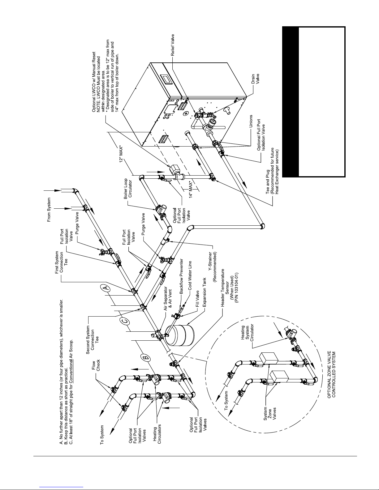
CAUTION
It is the installers responsibility to select pumps
and boiler piping congurations that provide the
proper ow rates and performance for the boiler
and indirect water heater.
Refer to Table 17 for recommended Boiler Loop
Circulator.
VI. Water Piping and Trim C. Standard Installation Requirements (continued)
103448-02 - 6/13 57
Figure 37: Near Boiler Piping - Heating Only
Page 58

CAUTION
It is the installers responsibility to select pumps
and boiler piping congurations that provide the
proper ow rates and performance for the boiler
and indirect water heater.
Refer to Table 17 for recommended Boiler Loop
Circulator.
VI. Water Piping and Trim C. Standard Installation Requirements (continued)
58 103448-02 - 6/13
Figure 38: Near Boiler Piping - Heating Plus Indirect Water Heater
Page 59
VI. Water Piping and Trim C. Standard Installation Requirements (continued)
of the discharge pipe must terminate in an unthreaded
pipe. If the relief valve is not piped to a drain, it must
terminate at least 6” above the oor. Do not run relief
valve discharge piping through an area prone to
freezing. The termination of discharge piping must be
in an area where it will not become plugged by debris.
WARNING
Safety relief valve discharge piping must be
piped such that the potential of severe burns
is eliminated. DO NOT pipe in any area where
freezing could occur. DO NOT install any shut-off
valves, plugs or caps. Consult Local Codes for
proper discharge piping arrangement.
2 Circulator (Required) – Usually at least two
circulators will be required to properly install a
Alpine™ Series boiler. See Paragraph B above for
information on sizing the circulators.
3. Expansion Tank (Required) – If this boiler is
replacing an existing boiler with no other changes
in the system, the old expansion tank can generally
be reused. If the expansion tank must be replaced,
consult the expansion tank manufacturer’s literature
for proper sizing.
4. Fill Valve (Required) – Either manual
(recommended) or automatic ll valve may be used.
However, if automatic rell is employed, a water
meter must be added to evaluate the makeup water
volume taken after initial ll and eliminate any
water leakage as early as possible.
5. Automatic Air Vent (Required) –At least one
automatic air vent is required. Manual vents will
usually be required in other parts of the system to
remove air during initial ll.
6. Manual Reset High Limit (Required by some
Codes) – This control is required by ASME CSD-1
and some other codes. Install the high limit in the
boiler supply piping just above the boiler with no
intervening valves. Set the manual reset high limit
to 200°F. Wire the limit per Figures 43 and 45A in
Section VIII Electrical.
7. Flow Control Valve (Strongly Recommended) –
The ow control valve prevents ow through the
system unless the circulator is operating. Flow
control valves are used to prevent gravity circulation
or “ghost ows” in circulator zone systems through
zones that are not calling for heat.
8. Y-strainer (Recommended) – A Y-strainer or
equivalent strainer removes heating system debris
from hydronic systems and protects boiler heat
exchanger from fouling up. Install the strainer
downstream of full port isolation valve, at the inlet
side of the circulator, for easy service.
9. Isolation Valves (Strongly recommended) –
Isolation valves are useful when the boiler must be
drained, as they will eliminate having to drain and
rell the entire system.
10. Drain Valve (Required) – Drain valve is packaged
loose with boiler and must be installed in the
location shown in Figure 36 “Factory Supplied
Piping and Trim Installation” of the Installation,
Operating and Service Instructions.
11. Low Water Cutoff (Required by some Codes) –
LWCO with harness is available as optional kit.
Order Complete Kit (Part Number 102097-01) when
required.
D. Special Situation Installation Requirements
Observe the following guidelines when making the
actual installation of the boiler piping for special
situations:
1. Systems containing high level of dissolved oxygen
– Many hydronic systems contain enough dissolved
oxygen to cause severe corrosion damage to Alpine
(ALP) boiler heat exchanger. Some examples
include but not limited to:
• Radiant systems employing tubing without
oxygen barrier
• Systems with routine additions of fresh water
• Systems open to atmosphere
If the boiler is used in such a system, it must be
separated from oxygenated water being heated with
a heat exchanger as shown in Figure 39. Consult
the heat exchanger manufacturer for proper heat
exchanger sizing as well as ow and temperature
requirements. All components on the oxygenated
side of the heat exchanger, such as the pump
and expansion tank, must be designed for use in
oxygenated water.
2. Piping with a Chiller - If the boiler is used in
conjunction with a chiller, pipe the boiler and chiller
in parallel. Use isolation valves to prevent chilled
water from entering the boiler.
Table 19: Multiple Boiler Water Manifold Sizing
Number of Boilers
Boiler Model
ALP080B 1¼” 1½” 1½” 2” 2” 2” 2½”
ALP105B 1¼” 1½” 2” 2” 2½” 2½” 2½”
ALP150B 1½” 2” 2½” 3” 3” 3” 3”
ALP210B 2” 2½” 2½” 3” 3½” 3½” 3½”
ALP285B 2” 3” 3” 3½” 4” 4” 5”
ALP399 2½” 3” 3” 4” 5” 5” 5”
2 3 4 5 6 7 8
Recommended Minimum Common Water
Manifold Size (NPT)
103448-02 - 6/13 59
Page 60
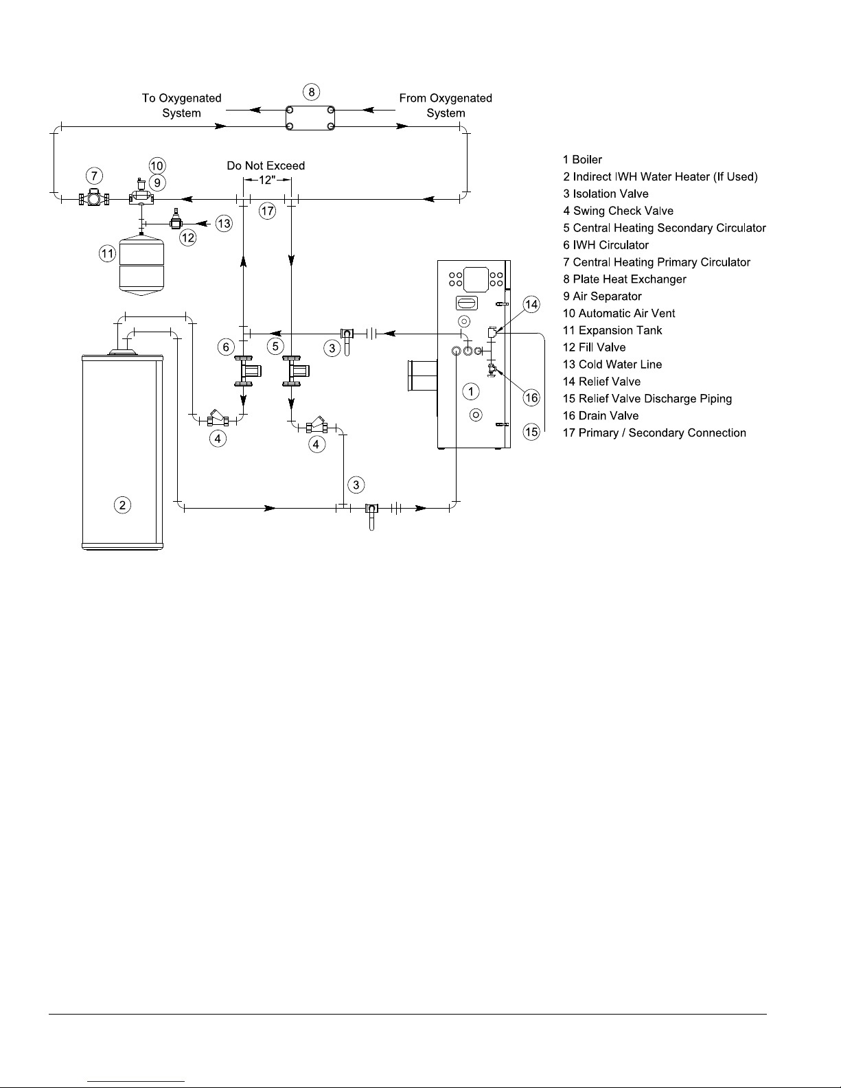
VI. Water Piping and Trim E. Multiple Boiler Installation Water Piping (continued)
Figure 39: Isolation of the Boiler From Oxygenated Water with A Plate Heat Exchanger
3. Boiler Piping with Air Handlers - Where the
boiler is connected to air handlers through which
refrigerated air passes, use ow control valves in the
boiler piping or other automatic means to prevent
gravity circulation during the cooling cycle.
E. Multiple Boiler Installation Water Piping – (See
Table 19 and Figures 40B and 41B)
1. Refer to this Section of this manual for:
a. Installation of Factory Supplied Piping and Trim
Components for an individual module (boiler).
b. Regarding an individual module (boiler) piping
system specic details.
c. Selection criteria for individual module (boiler)
space heating and/or DHW circulators.
2. For installations where indirect domestic hot water
heater is combined with space heating, when sizing
an indirect water heater circulator, compare the
specied ow range through an Alpine model boiler
to an indirect water heater (Alliance SL™) model
coil ow rate required to achieve water heater
rating. Refer to Table 20 and Figures 41A and 41B.
a. When Alliance SL™ model coil ow rate,
required to achieve water heater rating, falls
within the specied ow range for Alpine
boiler model, the Alliance SL™ model can be
piped as part of Alpine near-boiler piping.
Refer to Table 20 and Figures 41A and 41B.
b. When Alliance SL™ model coil ow rate,
required to achieve water heater rating,
exceeds the specied ow range for Alpine
boiler model, the Alliance SL™/Alpine boiler
combination may result in excessive noise and
boiler heat exchanger erosion, and therefore,
is not recommended. Refer to Table 20 and
Figures 41A and 41B for details.
c. When Alliance SL™ model coil ow rate,
required to achieve water heater rating, falls
below the specied ow range for Alpine boiler
model, the Alliance SL™ model must be piped
as a separate heating zone off the system
header. The circulator must be sized based on
the Alliance SL™ model coil ow and combined
coil pressure drop and the zone piping total
equivalent length. Refer to Table 20 and Figures
41A and 41B for details.
60 103448-02 - 6/13
Page 61
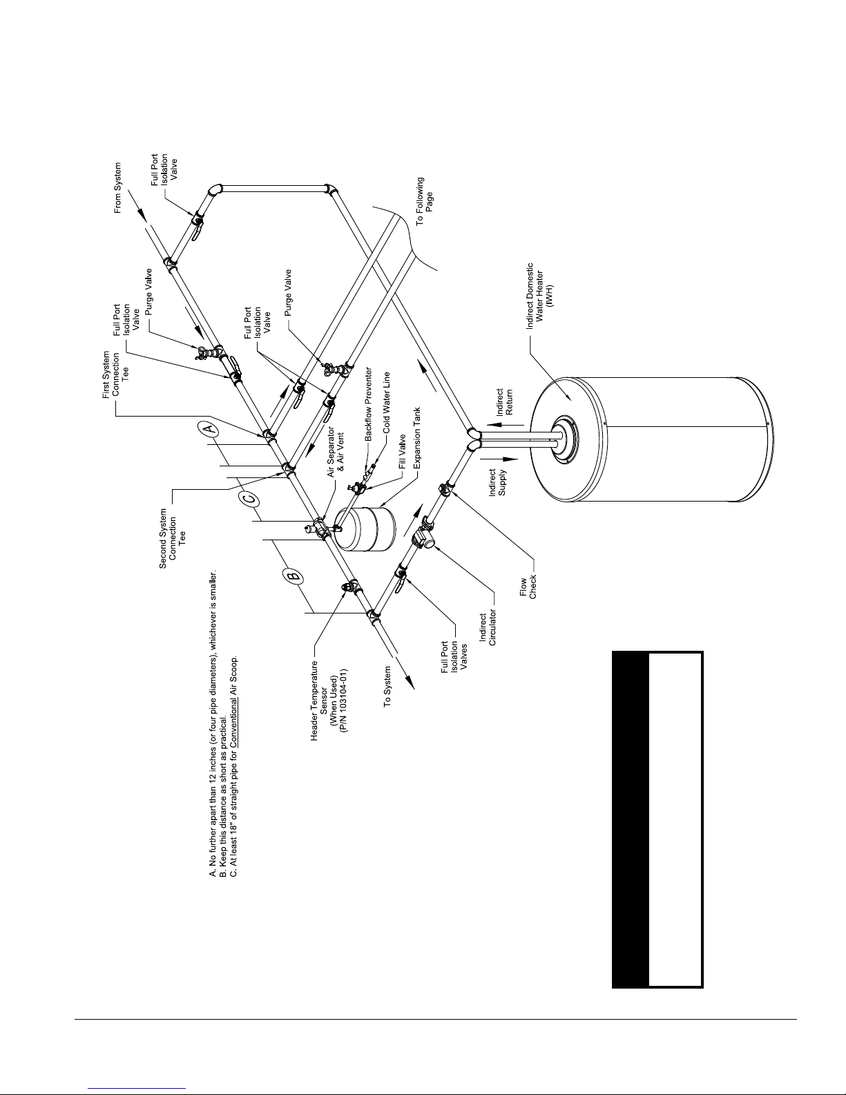
VI. Water Piping and Trim E. Multiple Boiler Installation (continued)
103448-02 - 6/13 61
Figure 40A: Multiple Boiler Water Piping w/Domestic Hot Water Heater (Page 1 of 2)
NOTICE
Installing a low water cutoff in the system piping
of multiple boilers is strongly recommended and
may be required by Local Codes.
Page 62
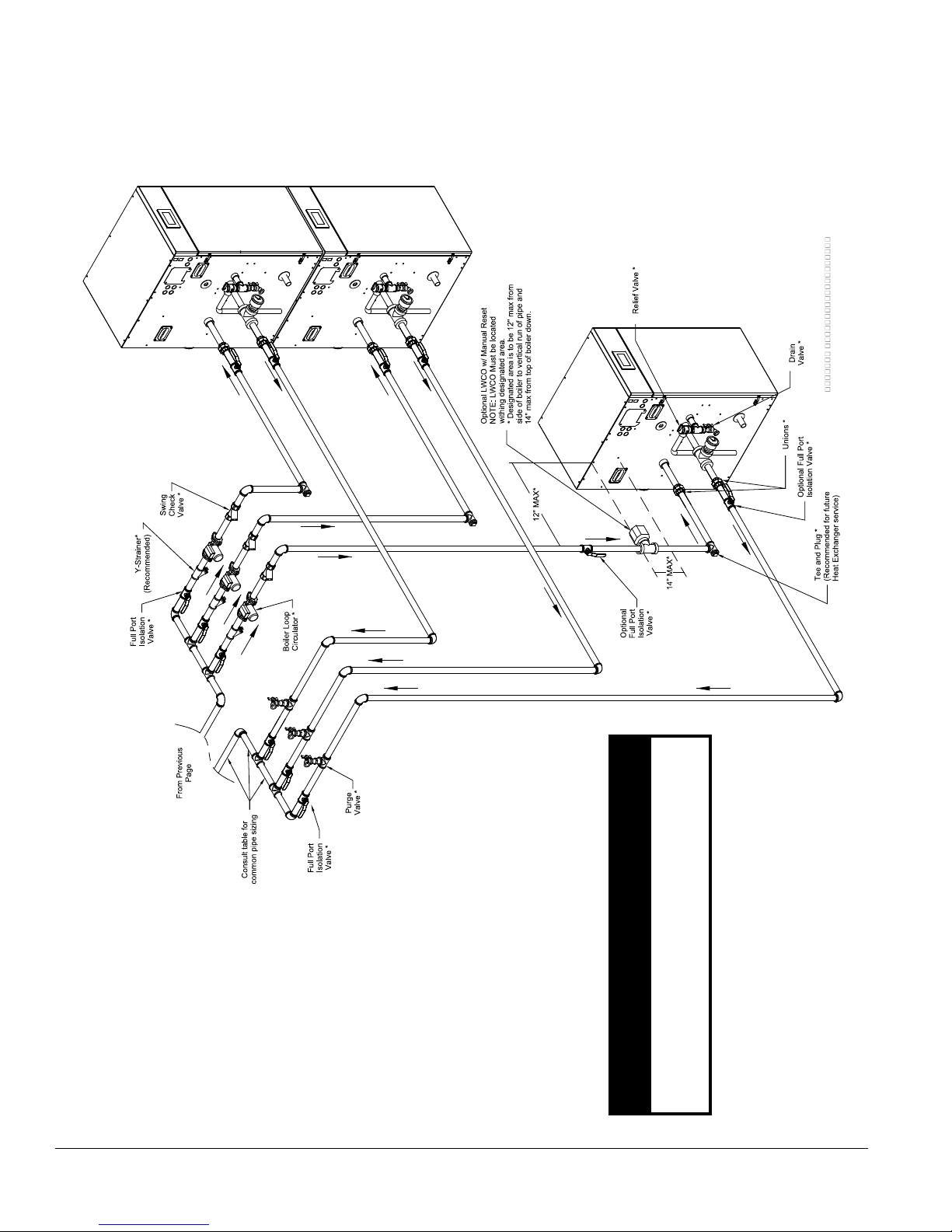
VI. Water Piping and Trim E. Multiple Boiler Installation (continued)
62 103448-02 - 6/13
Figure 40B: Multiple Boiler Water Piping w/Domestic Hot Water Heater (Page 2 of 2)
NOTICE
Installing a low water cutoff in the system piping
of multiple boilers is strongly recommended and
may be required by Local Codes.
Page 63
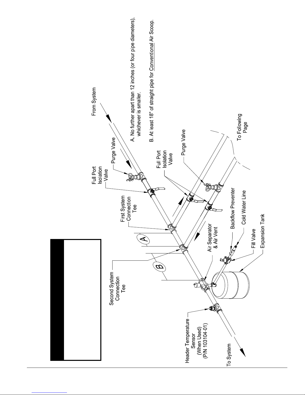
CAUTION
It is the installers responsibility to select pumps
and boiler piping congurations that provide the
proper ow rates and performance for the boiler
and indirect water heater.
Refer to Table 17 for recommended Boiler Loop
VI. Water Piping and Trim E. Multiple Boiler Installation (continued)
103448-02 - 6/13 63
Circulator.
Figure 41A: Alternate Multiple Boiler Water Piping w/ Indirect Domestic Hot Water Heater (Page 1 of 2)
Page 64
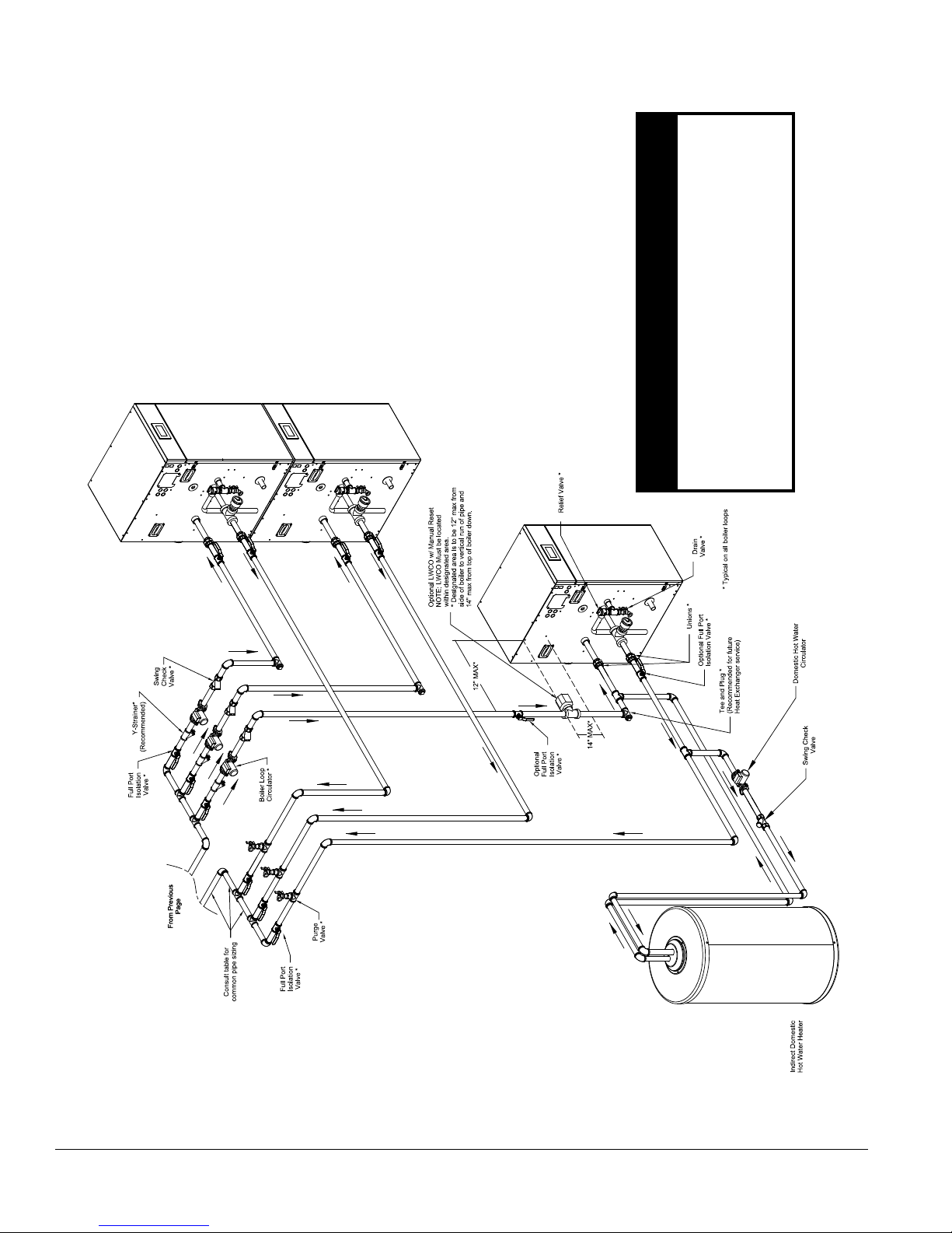
CAUTION
It is the installers responsibility to select pumps
and boiler piping congurations that provide the
proper ow rates and performance for the boiler
and indirect water heater.
Refer to Table 20 for recommended Boiler Loop
Circulator.
VI. Water Piping and Trim E. Multiple Boiler Installation (continued)
64 103448-02 - 6/13
Figure 41B: Alternate Multiple Boiler Water Piping w/Indirect Domestic Hot Water Heater (Page 2 of 2)
Page 65
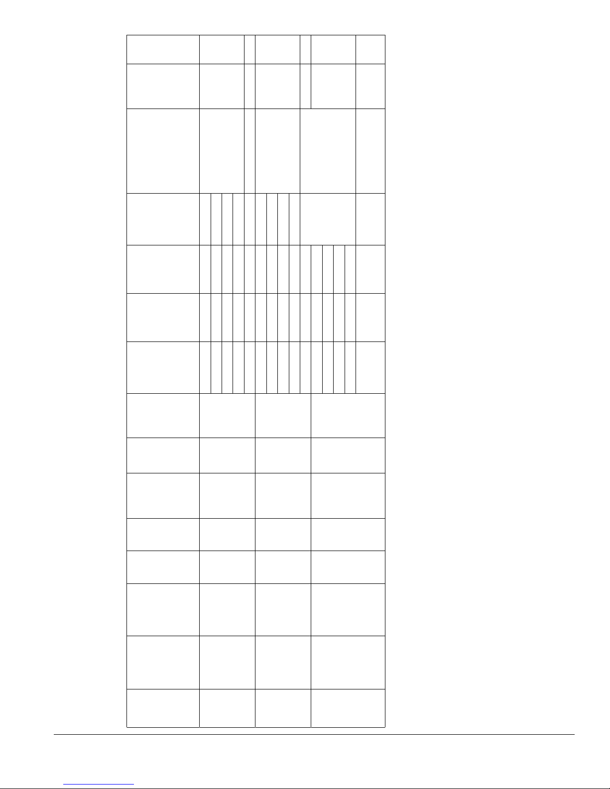
Notes
Figure
Reference
as Part of
Circulator
*Recommended
Make & Model for
Alliance SL installed
Boiler,
& Piping
Combined
Alliance
Alliance
Alliance SL
Loop Head
Alliance SL
Head
SL Coil
Required
Loss, Ft @
SL
Coil
Required
Flow Rate,
Models to
As Part of
Near-Boiler
be installed
41B
Taco 0014
FC (second speed)
Near-Boiler Piping
Grundfos UPS26-99
Loss, Ft
Flow Rate
GPM
SL27 6 9 19.3
SL35 6 9 19.3
SL50 6 9.5 19.8
Piping
SL70 6 10 20.3
41B
Taco 0014
Grundfos UPS26-99
SL27 6 9 19.3
SL35 6 9 19.3
SL119 14 17 NA Not Recommended NA Note 1
NA Note 1
41B Note 2
FC (second speed)
NA Not Recommended
SL50 6 9.5 19.8
SL70 6 10 20.3
SL27 6 9
SL35 6 9
SL119 14 17
SL50 6 9.5
41B
(max speed)
Taco 1400-45
Grundfos UPS 32-80/2
SL70 6 10
SL119 14 17 36
DT
GPM
Boiler,
@ 35°F
Flow thru
Min Req’d
DT
GPM
Flow,
@ 25°F
Max
Boiler,
GPM @
20°F DT
Flow thru
Allowable
Inch
Pipe
Piping
Return
Pipe
Piping
Supply
Return
Inch, FPT
Connection,
Supply
Inch, FPT
Connection,
Boiler
Model
Size,
Inch
Size,
ALP080B 1 1 1 1 7.3 5.8 4.2
Near-
Boiler
Near-
Boiler
Boiler
Boiler
VI. Water Piping and Trim E. Multiple Boiler Installation (continued)
Table 20: Recommended Circulator Models for Alpine (ALP) Boilers and Alliance SL Indirect Water Heaters
Installed as Part of Near-Boiler Piping Up to 75 Ft. Equivalent Length - Domestic Hot Water Circulator
ALP105B 1 1 1 1 9.6 7.7 5.5
ALP150B 1 1 1 1 13.8 11 7.9
NOTES:
Note 1: Required Alliance SL Coil Flow Rate exceeds Max Allowable Flow Rate thru Boiler; this Boiler/Alliance SL combination may result in boiler heat exchanger erosion and noise.
Note 2: Required Alliance SL Coil Flow Rate is below Min Required Flow Rate thru Boiler; this Model can only be installed as separate heating zone off system header - see Figure 40A for alternate
IWH piping. Indirect Water Heater Circulator must be selected by an installer based on Alliance SL required coil ow and corresponding coil head loss shown as well as total equivalent length of
such separate zone.
Note 3: Combined Head Loss shown corresponds to Min Required Flow Rate thru Boiler.
* Circulator Models shown are not equipped with internal ow check valve (IFC).
When selecting Circulators with IFC contact Circulator Manufacturer for sizing information.
Near-Boiler Piping Size shown is based on 2 to 5.5 Ft/sec velocity range to avoid potential noise and pipe erosion.
103448-02 - 6/13 65
Page 66
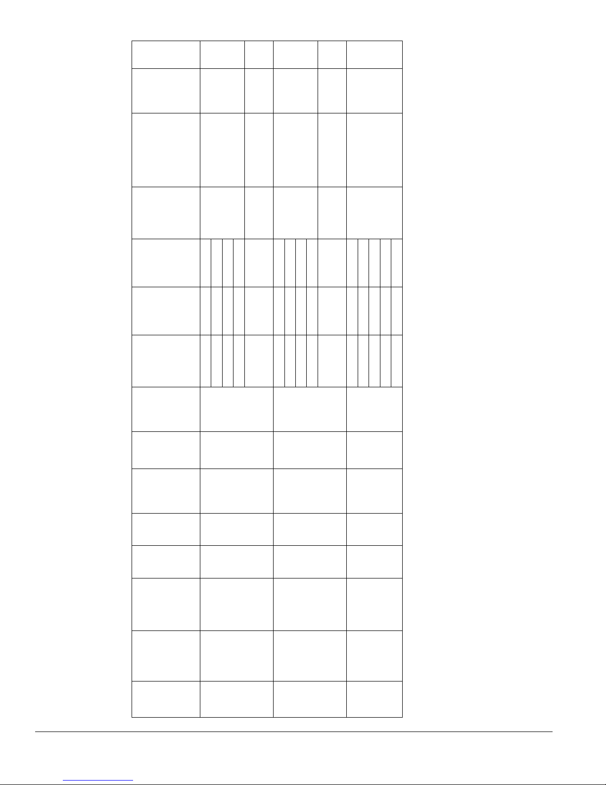
Notes
Figure
Reference
Model for
Alliance SL
*Recommended
Circulator Make &
Boiler,
Combined
SL Coil
Alliance
SL
Alliance
Models to
Alliance SL
of Near-Boiler
installed as Part
& Piping
Loop Head
Alliance SL
Head
Required
Loss, Ft @
Coil
Required
Flow Rate,
As Part of
Near-Boiler
be installed
Piping
Loss, Ft
Flow Rate
GPM
SL27 6 9
Piping
NA Not Recommended 41B Note 2
SL35 6 9
SL50 6 9.5
SL70 6 10
41B
Taco 1400-45
80/2 (max speed)
Grundfos UPS 32-
SL35 6 9
SL27 6 9
SL119 14 17 29.7
NA Not Recommended 41B Note 2
SL50 6 9.5
41B Note 3
Taco 1400-45
80/2 (max speed)
Grundfos UPS 32-
SL70 6 10
SL119 14 17.0 27.0
NA Not Recommended 41B Note 2
SL35 6 9
SL50 6 9.5
SL27 6 9
SL70 6 10
SL119 14 17.0
Boiler,
Flow thru
Min Req’d
GPM
Flow,
Max
Flow thru
Allowable
Near-
Boiler
Piping
Near-
Boiler
Piping
Boiler
Return
Boiler
Supply
DT
GPM
@ 35°F
DT
@ 25°F
Boiler,
GPM @
20°F DT
Inch
Pipe
Size,
Return
Inch
Pipe
Size,
Supply
Inch, FPT
Connection,
Inch, FPT
Connection,
VI. Water Piping and Trim E. Multiple Boiler Installation (continued)
Table 20 (continued): Recommended Circulator Models for Alpine (ALP) Boilers and Alliance SL Indirect Water Heaters
Installed as Part of Near-Boiler Piping Up to 75 Ft. Equivalent Length - Domestic Hot Water Circulator
Boiler
Model
66 103448-02 - 6/13
ALP210B 1 1 1-1/4 1-1/4 19.4 15.5 11.1
ALP285B 1-1/4 1-1/4 1-1/2 1-1/2 26.5 21.2 15.1
ALP399 1-1/2 1-1/2 2 2 37.7 30.2 21.5
NOTES:
Note 1: Required Alliance SL Coil Flow Rate exceeds Max Allowable Flow Rate thru Boiler; this Boiler/Alliance SL combination may result in boiler heat exchanger erosion and noise.
Note 2: Required Alliance SL Coil Flow Rate is below Min Required Flow Rate thru Boiler; this Model can only be installed as separate heating zone off system header - see Figure 40A for alternate IWH
piping. Indirect Water Heater Circulator must be selected by an installer based on Alliance SL required coil ow and corresponding coil head loss shown as well as total equivalent length of such
separate zone.
Note 3: Combined Head Loss shown corresponds to Min Required Flow Rate thru Boiler.
* Circulator Models shown are not equipped with internal ow check valve (IFC).
When selecting Circulators with IFC contact Circulator Manufacturer for sizing information.
Near-Boiler Piping Size shown is based on 2 to 5.5 Ft/sec velocity range to avoid potential noise and pipe erosion.
Page 67
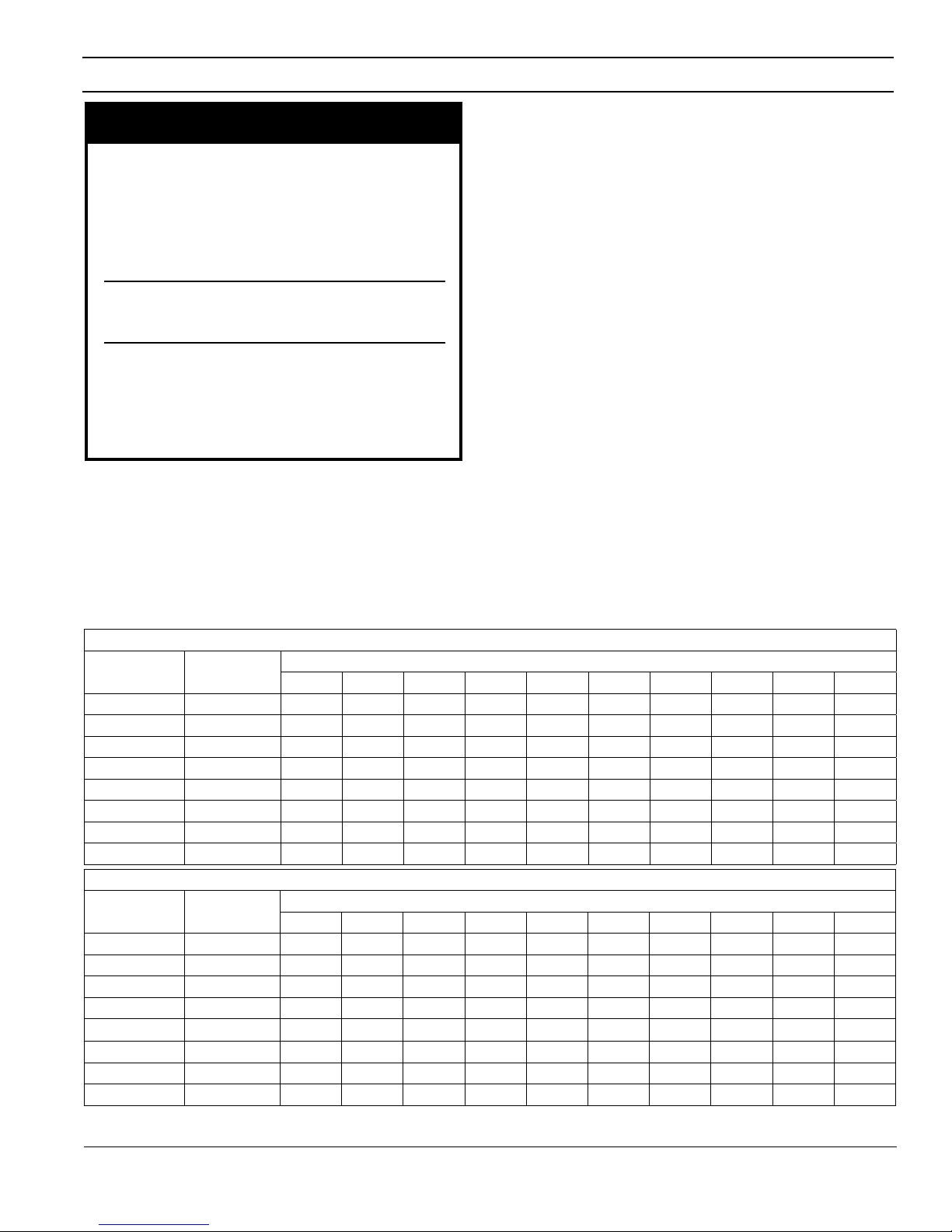
VII. Gas Piping
contact gas supplier for additional information.
WARNING
Failure to properly pipe gas supply to boiler
may result in improper operation and damage
to the boiler or structure. Always assure
gas piping is absolutely leak free and of the
proper size and type for the connected load.
An additional gas pressure regulator may be
needed. Consult gas supplier.
Size corrugated stainless steel tubing (CSST)
to ensure proper capacity and minimize ow
restrictions.
Use two wrenches when tightening gas
piping at boiler, using one wrench to
prevent the boiler gas valve from turning.
Failure to support the boiler gas valve to
prevent it from turning could damage gas
valve components.
A. Size gas piping. Design system to provide adequate gas
supply to boiler. Consider these factors:
1. Allowable pressure drop from point of delivery to
boiler. Maximum allowable system pressure is ½
psig. Actual point of delivery pressure may be less;
Table 21A: Maximum Capacity of Schedule 40 Black Pipe in CFH* (Natural Gas) For Gas Pressures
of 0.5 psig or Less
Inlet Pressure 0.5 PSI or less; 0.3 Inch W.C. Pressure Drop
Nominal Pipe
Size, In.
½ 0.622 131 90 72 62 55 50 46 42 40 38
¾ 0.824 273 188 151 129 114 104 95 89 83 79
1 1.049 514 353 284 243 215 195 179 167 157 148
1¼ 1.380 1056 726 583 499 442 400 368 343 322 304
1½ 1.610 1582 1087 873 747 662 600 552 514 482 455
2 2.067 3046 2094 1681 1439 1275 1156 1063 989 928 877
2½ 2.469 4856 3337 2680 2294 2033 1842 1695 1576 1479 1397
3 3.068 8584 5900 4738 4055 3594 3256 2996 2787 2615 2470
Nominal Pipe
Size, In.
½ 0.622 172 11 8 95 81 72 65 60 56 52 50
¾ 0.824 360 247 199 170 151 137 126 117 11 0 104
1 1.049 678 466 374 320 284 257 237 220 207 195
1¼ 1.380 1392 957 768 657 583 528 486 452 424 400
1½ 1.610 2085 1433 1151 985 873 791 728 677 635 600
2 2.067 4016 2760 2217 1897 1681 1523 1402 1304 1223 1156
2½ 2.469 6401 4400 3533 3024 2680 2428 2234 2078 1950 1842
3 3.068 11316 7778 6246 5345 4738 4293 3949 3674 3447 3256
* 1 CFH of Natural Gas is approximately equal to 1 MBH; contact your gas supplier for the actual heating value of your
gas.
Inside
Diameter, In.
Inside
Diameter, In.
10 20 30 40 50 60 70 80 90 100
Inlet Pressure 0.5 PSI or less; 0.5 Inch W.C. Pressure Drop
10 20 30 40 50 60 70 80 90 100
For materials or conditions other than those listed
Minimum gas valve inlet pressure is stamped on
the rating label located in the boiler’s vestibule
compartment.
2. Maximum gas demand. Refer to the boiler’s input as
printed on its rating label. Also consider existing and
expected future gas utilization equipment (i.e. water
heater, cooking equipment).
3. Length of piping and number of ttings. Refer
to Tables 21A (natural gas) or 21B (LP gas) for
maximum capacity of Schedule 40 pipe. Table 22
lists equivalent pipe length for standard ttings.
4. Specic gravity of gas. Gas piping systems for gas
with a specic gravity of 0.60 or less can be sized
directly from Tables 21A or 21B, unless authority
having jurisdiction species a gravity factor be
applied. For specic gravity greater than 0.60,
apply gravity factor from Table 23. If exact specic
gravity is not shown choose next higher value.
above, refer to National Fuel Gas Code, NFPA54/
ANSI Z223.1, and/or CAN/CSA B149.1 Natural Gas
and Propane Installation Code. or size system using
standard engineering methods acceptable to authority
having jurisdiction.
Length of Pipe, Ft.
Length of Pipe, Ft.
103448-02 - 6/13 67
Page 68
VII. Gas Piping (continued)
Table 21B: Maximum Capacity of Schedule 40 Black Pipe in CFH* (LP Gas) For Gas Pressures
of 0.5 psig or Less
Inlet Pressure 11.0 Inch W.C.; 0.3 Inch W.C. Pressure Drop
Nominal
Pipe Size, In.
½ 0.622 88 60 48 41 37 33 31 29 27 25
¾ 0.824 184 126 101 87 77 70 64 60 56 53
1 1.049 346 238 191 163 145 131 121 112 105 100
1¼ 1.380 710 488 392 336 297 269 248 231 216 204
1½ 1.610 1064 732 588 503 446 404 371 346 324 306
2 2.067 2050 1409 1131 968 858 778 715 666 624 590
2½ 2.469 3267 2246 1803 1543 1368 1239 1140 1061 995 940
3 3.068 5776 3970 3188 2729 2418 2191 2016 1875 1760 1662
Nominal
Pipe Size, In.
½ 0.622 116 80 64 55 48 44 40 38 35 33
¾ 0.824 242 166 134 114 101 92 85 79 74 70
1 1.049 456 314 252 215 191 173 159 148 139 131
1¼ 1.380 937 644 517 442 392 355 327 304 285 269
1½ 1.610 1403 964 775 663 588 532 490 456 427 404
2 2.067 2703 1858 1492 1277 1131 1025 943 877 823 778
2½ 2.469 4308 2961 2377 2035 1803 1634 1503 1399 1312 1239
3 3.068 7615 5234 4203 3597 3188 2889 2658 2472 2320 2191
Inside
Diameter, In.
Inside
Diameter, In.
Length of Pipe, Ft.
10 20 30 40 50 60 70 80 90 100
Inlet Pressure 11.0 Inch W.C.; 0.5 Inch W.C. Pressure Drop
Length of Pipe, Ft.
10 20 30 40 50 60 70 80 90 100
* 1 CFH of LP Gas is approximately equal to 2.5 MBH; contact your gas supplier for the actual heating value
of your gas.
Table 22: Equivalent Lengths of Standard Pipe Fittings & Valves
Nominal
Pipe Size,
Inc.
½ 0.622 0.4 17.3 8.7 4.3 0.7 1.6 3.5 1.6 3.1
¾ 0.824 0.5 22.9 11.4 5.7 1.0 2.1 4.6 2.1 4.1
1 1.049 0.6 29.1 14.6 7.3 1.2 2.6 5.8 2.6 5.2
1¼ 1.38 0.8 38.3 19.1 9.6 1.6 3.5 7.7 3.5 6.9
1½ 1.61 0.9 44.7 22.4 11.2 1.9 4.0 9.0 4.0 8.0
2 2.067 1.2 57.4 28.7 14.4 2.4 5.2 11.5 5.2 10.3
2½ 2.469 1.4 68.5 34.3 17.1 2.9 6.2 13.7 6.2 12.3
3 3.068 1.8 85.2 42.6 21.3 3.6 7.7 17.1 7.7 15.3
Inside
Diameter,
In.
Valves (Screwed) - Fully Open Screwed Fittings
180 Close
Return
Bend
Flow Thru
Gate Globe Angle
Swing
Check
45°
Elbow
90°
Elbow
90 Tee
Run
90 Tee, Flow
Thru Branch
68 103448-02 - 6/13
Page 69
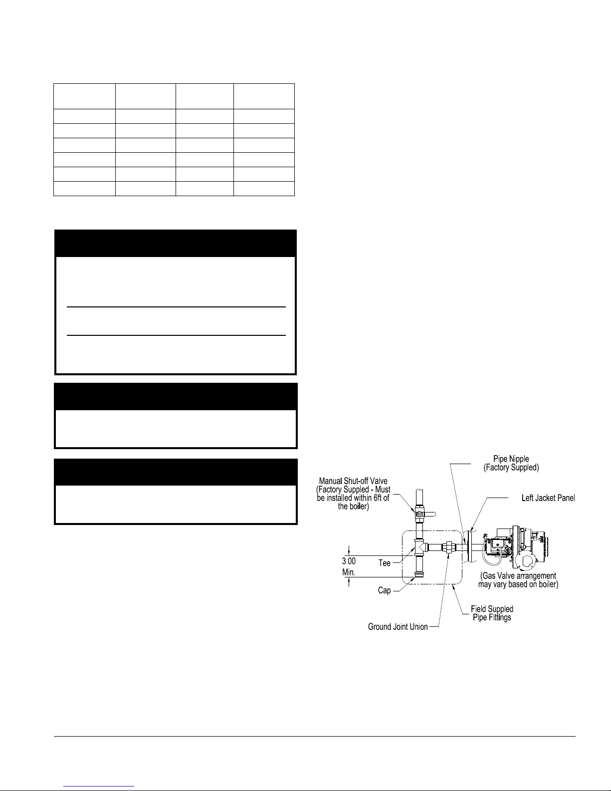
VII. Gas Piping (continued)
Table 23: Specic Gravity Correction Factors
Specic
Gravity
0.60 1.00 0.90 0.82
0.65 0.96 1.00 0.78
0.70 0.93 1.10 0.74
0.75 0.90 1.20 0.71
0.80 0.87 1.30 0.68
0.85 0.81 1.40 0.66
Correction
Factor
Specic
Gravity
Correction
Factor
B. Connect boiler gas valve to gas supply system.
CAUTION
The gas valve and blower will not support
the weight of the piping. Do not attempt to
support the weight of the piping with the
boiler gas valve.
Ensure that the high gas pressure regulator
is at least 6 to 10 feet upstream of the boiler.
It is very important that the gas line is
properly purged by the gas supplier or
utility company.
WARNING
Failure to use proper thread compounds on all
gas connectors may result in leaks of ammable
gas.
3. Alpine (ALP) boilers have factory supplied
Miscellaneous Part Carton (P/N 101777-01 ALP080B thru ALP210B; 101777-02 - ALP285B;
1012942-03 - ALP399), which includes gas piping
components to connect boiler gas valve to gas
supply system. Install these components prior to
connecting boiler to gas supply system piping as
follows:
a. Locate and remove either ½” NPT x 6” long
black nipple and ½” NPT external gas shutoff
valve (ALP080B thru ALP210B), or ¾” NPT x
6” long black nipple and ¾” NPT external gas
shutoff valve (ALP285B thru ALP399).
b. Feed the appropriate nipple through factory
installed jacket left side panel grommet (refer
to Figure 1A or 1B for gas supply connection
identication) and screw the nipple into boiler
gas valve inlet port.
c. Mount the appropriate external gas shutoff valve
onto the threaded nipple end outside of the jacket
left side panel.
d. Install sediment trap, ground-joint union and
manual shut-off valve upstream of mounted
factory supplied manual shut-off valve. See
Figure 42.
4. All above ground gas piping upstream from manual
shut-off valve must be electrically continuous and
bonded to a grounding electrode. Do not use gas
piping as grounding electrode. Refer to National
Electrical Code, NFPA 70.
WARNING
Gas supply to boiler and system must be
absolutely shut off prior to installing or servicing
boiler gas piping.
1. Use methods and materials in accordance with local
plumbing codes and requirements of gas supplier. In
absence of such requirements, follow National Fuel
Gas Code, NFPA 54/ANSI Z223.1, and/or CAN/
CSA B149.1 Natural Gas and Propane Installation
Code.
2. Use thread (joint) compounds (pipe dope) resistant
to action of liqueed petroleum gas.
Figure 42: Recommended Gas Piping
103448-02 - 6/13 69
Page 70
VII. Gas Piping (continued)
C. Pressure test. See Table 24 for Alpine Min./Max.
Pressure Ratings. The boiler and its gas connection
must be leak tested before placing boiler in operation.
1. Protect boiler gas control valve. For all testing over
½ psig, boiler and its individual shutoff valve must
be disconnected from gas supply piping. For testing
at ½ psig or less, isolate boiler from gas supply
piping by closing boiler’s individual manual shutoff
valve.
2. Locate leaks using approved combustible gas noncorrosive leak detector solution.
Table 24: Min./Max. Pressure Ratings
LP Gas
Min.
Pressure
Inlet to Gas
Valve
(in. w.c.)
Boiler
Model
No.
ALP080B
ALP105B
ALP150B
ALP210B
ALP285B
ALP399
Natural/LP
Gas Max.
Pressure
(in. w.c.)
14 4.0 11.0
Natural Gas
Min. Pressure
Inlet to Gas
Valve
(in. w.c.)
D. Gas Piping for Multiple Boiler Installation
1. Individual module (boiler) gas pipe sizing specic
details – see paragraph A.
2. Individual module (boiler) recommended gas piping
detail - see Figure 42.
3. An additional gas pressure regulator(s) may need to
be to installed to properly regulate inlet gas pressure
at the smallest individual module (boiler).
DANGER
Do not use matches, candles, open ames or
other ignition source to check for leaks.
WARNING
If gas pressure in the building is above ½ psig,
an additional gas pressure regulator is required.
Using one additional regulator for multiple
boilers may result in unsafe boiler operation.
The additional regulator must be able to properly
regulate gas pressure at the input of the smallest
boiler. If the regulator cannot do this, two or
more additional regulators are required. Consult
regulator manufacturer and/or local gas supplier
for instructions and equipment ratings.
70 103448-02 - 6/13
Page 71
VIII. Electrical
DANGER
Positively assure all electrical connections are unpowered before attempting installation or service of
electrical components or connections of the boiler or building. Lock out all electrical boxes with padlock
once power is turned off.
WARNING
Failure to properly wire electrical connections to the boiler may result in serious physical harm.
Electrical power may be from more than one source. Make sure all power is off before attempting any
electrical work.
Each boiler must be protected with a properly sized over-current device.
Never jump out or make inoperative any safety or operating controls.
The wiring diagrams contained in this manual are for reference purposes only. Each boiler is shipped with
a wiring diagram attached to the front door. Refer to this diagram and the wiring diagram of any controls
used with the boiler. Read, understand and follow all wiring instructions supplied with the controls.
IMPORTANT
This boiler is equipped with a feature that saves energy by reducing the boiler water temperature as the
heating load decreases. This feature is equipped with an override which is provided primarily to permit the
use of an external energy management system that serves the same function. THIS OVERRIDE MUST NOT
BE USED UNLESS AT LEAST ONE OF THE FOLLOWING CONDITIONS IS TRUE:
• An external energy management system is installed that reduces the boiler water temperature as
the heating load decreases.
• This boiler is not used for any space heating.
• This boiler is part of a modular or multiple boiler system having a total input of 300,000 BTU/hr or
greater.
• This boiler is equipped with a tankless coil.
This notice applies to Models ALP080B through ALP285B Only (does not apply to ALP399).
NOTICE
This boiler is equipped with a high water temperature limit located inside the internal wiring of the boiler.
This limit provides boiler shutdown in the event the boiler water temperature exceeds the set point of the
limit control. Certain Local Codes require an additional water temperature limit. In addition, certain types
of systems may operate at temperatures below the minimum set point of the limit contained in the boiler.
If this occurs, install an additional water temperature limit (Honeywell L4006 Aquastat). Wire as indicated in
the Electrical Section of this manual.
NOTICE
All wire, wire nuts, controls etc. are installer supplied unless otherwise noted.
A. General. Install wiring and electrically ground boiler
in accordance with authority having jurisdiction or, in
the absence of such requirements, follow the National
Electrical Code, NFPA 70, and/or CSA C22.1 Electrical
Code.
B. A separate electrical circuit must be run from
the main electrical service with an over-current
device/disconnect in the circuit. A service switch is
103448-02 - 6/13 71
recommended and may be required by some local
jurisdictions. Install the service switch in the line
voltage “Hot” leg of the power supply. Locate the
service switch such that the boiler can be shut-off
without exposing personnel to danger in the event of
an emergency. Connect the main power supply and
ground to the three (3) boiler wires (black, white and
green) located in the junction box at the inside top of
the boiler jacket.
Page 72
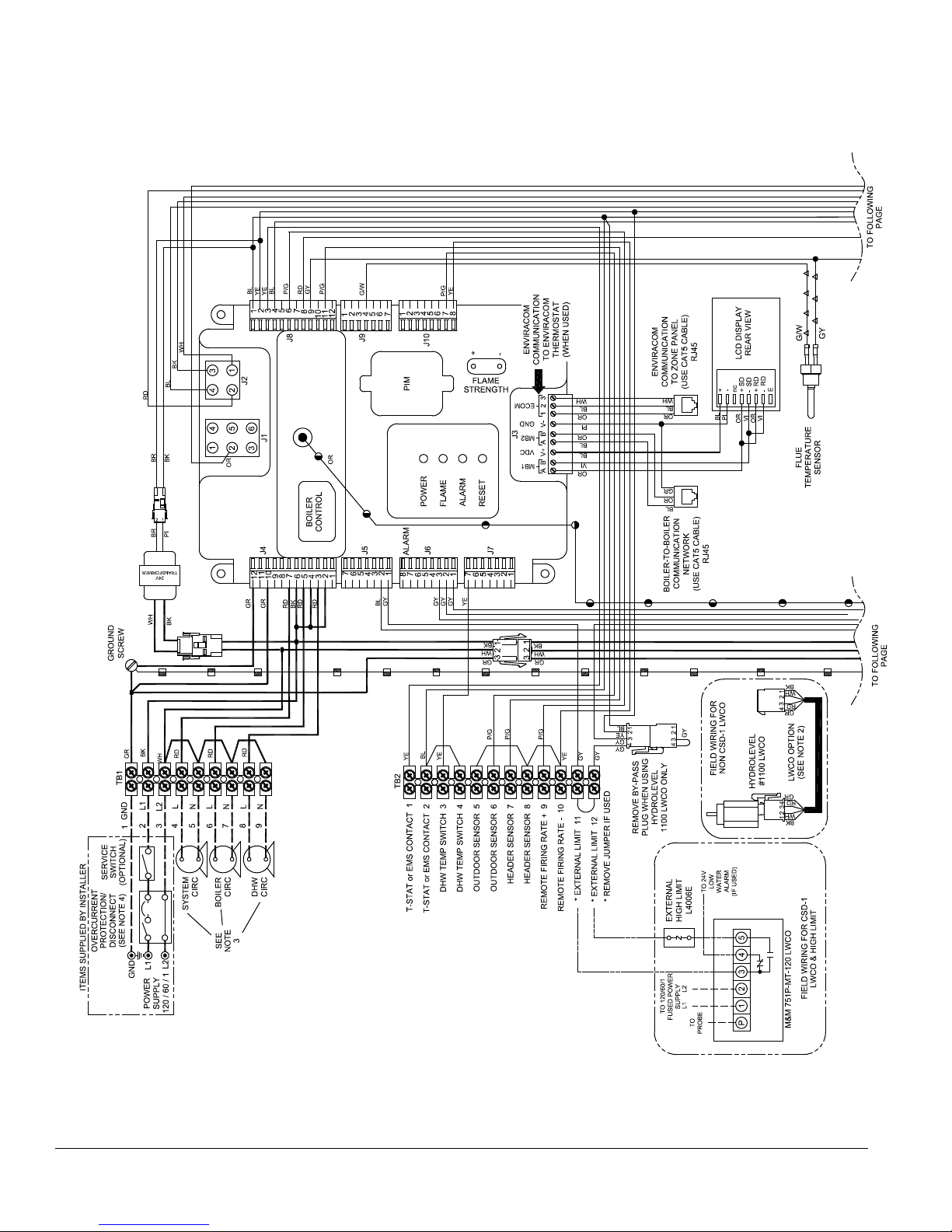
VIII. Electrical (continued)
72 103448-02 - 6/13
Page 73
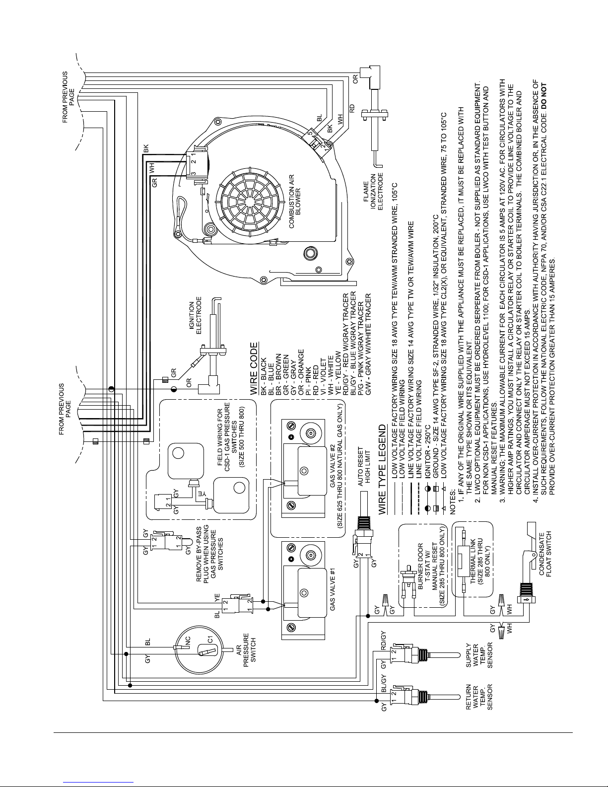
VIII. Electrical (continued)
103448-02 - 6/13 73
Figure 43: Wiring Connections Diagram
Page 74
VIII. Electrical (continued)
C. Refer to Figures 43 and 44 or details on the internal
boiler wiring.
Line Voltage (120 VAC) Connections - see Figure 43.
1. The line voltage connections are located in the
junction box on the left side of the vestibule. The
terminal block TB-1 in conjunction with terminal
screw identication label is attached to the junction
box combination cover/inside high voltage bracket.
2. The conductor insulation colors are:
a. Black – L1 line voltage “Hot”
b. White – L2 line voltage “Neutral” for boiler and
circulators
c. Red – Line voltage “Hot” for “Heating”
circulator, “System” circulator and “DHW”
circulator
d. Green – Ground connection
Low Voltage (24 VAC) Connections - see Figure 43.
3. The terminal block TB-2 in conjunction with
terminal screw identication label is attached to
the junction box front and located inside Control
compartment on the left side.
4. The connections are (listed identication label top to
bottom):
a. 1 – “Heating Thermostat”
b. 2 – “Heating Thermostat”
c. 3 – “DHW Temperature Switch”
d. 4 – “DHW Temperature Switch”
e. 5 – “Outdoor Sensor”
f. 6 – “Outdoor Sensor”
g. 7 – “Header Sensor”
h. 8 – “Header Sensor”
i. 9 – “Remote Firing Rate”
j. 10 – “Remote Firing Rate”
k. 11 – “External Limit”
l. 12 – “External Limit”
5. If the outdoor sensor is connected to terminals 5 and
6 “Outdoor Sensor”, the boiler will adjust the target
space heating set point supply water temperature
downwards as the outdoor air temperature increases.
If used, this sensor should be located on the outside
of the structure in an area where it will sense the
average air temperature around the house. Avoid
placing this sensor in areas where it may be covered
with ice or snow. Locations where the sensor will
pick up direct radiation from the sun should also
be avoided. Avoid placing the sensor near potential
sources of electrical noise such as transformers,
power lines, and uorescent lighting. Wire the
sensor to the boiler using 22 gauge or larger wire.
As with the sensor, the sensor wiring should be
routed away from sources of electrical noise. Where
it is impossible to avoid such noise sources, wire
the sensor using a 2 conductor, UL Type CM, AWM
Style 2092, 300Volt 60°C shielded cable. Connect
one end of the shielding on this cable to ground.
Table 25: Boiler Current Draw
Model Number
ALP080B <2
ALP105B <2
ALP150B <2
ALP210B <3
ALP285B <5
ALP399 <5
Nominal Current
(amps)
WARNING
When making low voltage connections, make
sure that no external power source is present in
the thermostat or limit circuits. If such a power
source is present, it could destroy the boiler’s
Microprocessor Control. One example of an
external power source that could be inadvertently
connected to the low voltage connections is a
transformer in old thermostat wiring.
D. Power Requirements
Nominal boilers current draw is provided in Table
25. These values are for planning purposes only
and represent only the boiler’s power consumption.
To obtain total system power consumption add any
selected circulator and component current draws.
E. Multiple Boiler Wiring
Install over-current protection in accordance with
authority having jurisdiction or, in the absence of such
requirements, follow the National Electric Code, NFPA
70, and/or CSA C22.1 Electrical Code. Do not provide
over-current protection greater than 15 amperes. If it
becomes necessary to provide greater amperes (because
of the number of boilers provided) use separate circuits
and over-current protection for additional boilers.
F. External Multiple Boiler Control System
As an alternate to the Control internal sequencer,
the Control also accepts an input from an external
sequencer. Follow multiple boiler control system
manufacturer (Honeywell, Tekmar, etc.) instructions
to properly apply a multiple boiler control system.
The Tekmar Model 264 and Model 265 based control
wiring diagrams (Figure 47A and 47B) are provided as
examples of typical multiple boiler control systems.
74 103448-02 - 6/13
Page 75
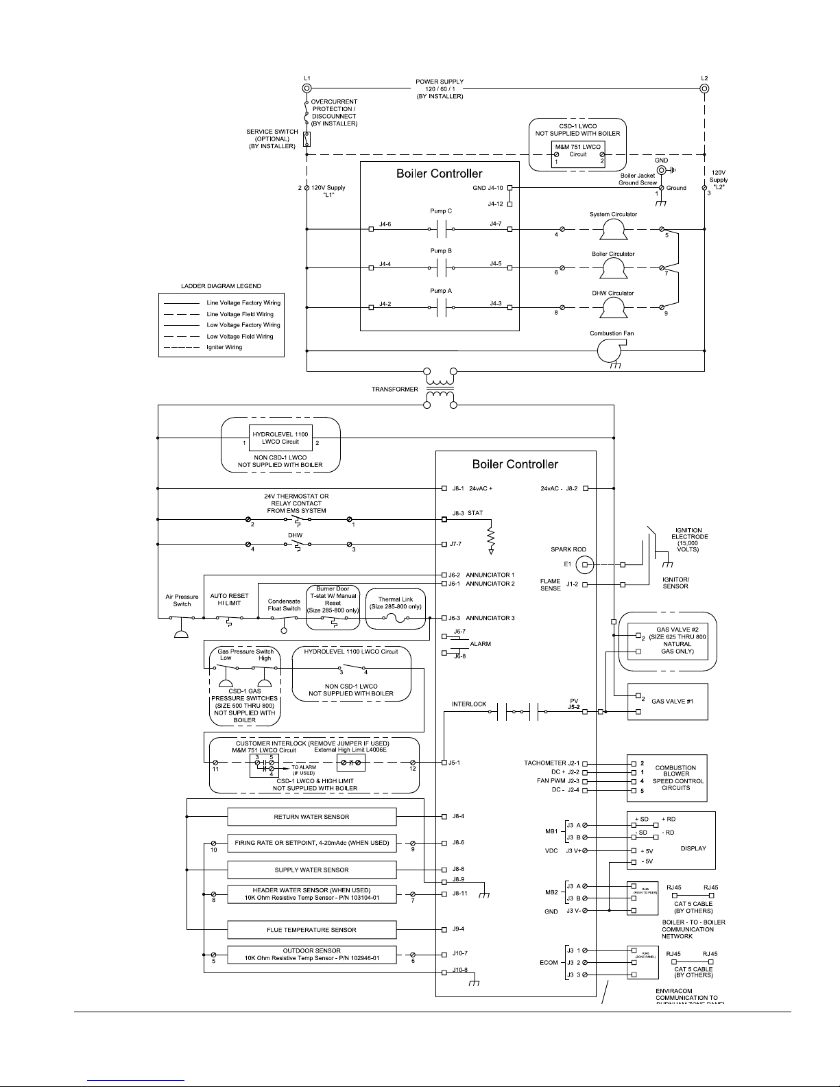
VIII. Electrical (continued)
Figure 44: Ladder Diagram
103448-02 - 6/13 75
Page 76
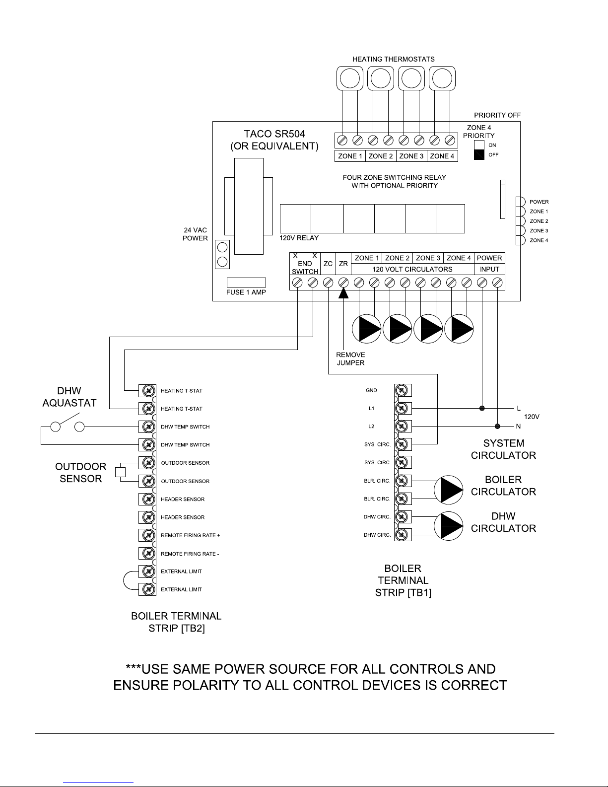
VIII. Electrical (continued)
Figure 45A: Modied Wiring For DHW Priority When Using Low Flow Circulator Piped Off System Header -
Heating (with Central Heating Circulators) Plus Alternately Piped Indirect Water Heater
76 103448-02 - 6/13
Page 77
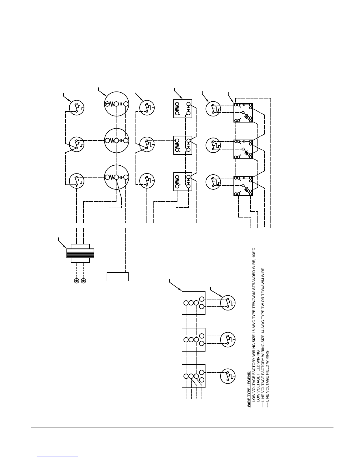
ALVES)
(SEE NOTE)
AT 0.9 AMPS (40VA REQ'D
W/ HEAT ANTICIPATOR SET
2 WIRE (24V) THERMOSTATS
FOR EVERY 3 ZONE VALVES)
TACO ZONE VALVES
AT 0.5 AMPS (40VA REQ'D
W/ HEAT ANTICIPATOR SET
2 WIRE (24V) THERMOSTATS
FOR EVERY 4 ZONE V
ZONE VALVES
HONEYWELL V8043E
AT 0.3 AMPS (40VA REQ'D
W/ HEAT ANTICIPATOR SET
2 WIRE (24V) THERMOSTATS
FOR EVERY 4 ZONE VALVES)
ZONE VALVES
#1361-102
WHITE ROGERS
3
2
3
2
1
231
X1
X2
FIELD INSTALLED
(SEE NOTE)
40VA TRANSFORMER
X3
X4
X1
YE
2
4
3
1
YE
RD
RD
RD
YE
YE YE
YE
X2
X3
RD
RD
X4
2
2
4
3
1
2
22
4
3
1
X3
X4
X2
X1
(SEE NOTE)
FLAIR "VJ"
ZONE VALVES
AT 0.9 AMPS (40VA REQ'D
W/ HEAT ANTICIPATOR SET
2 WIRE (24V) THERMOSTATS
N
L1
POWER
SUPPLY
120/60/1
TO SAGE2
HEATING T-STAT
2
1
3
4 5
54
2
1
3
5
1
2
3
4
X1
X2
X3
X4
FOR EVERY 6 ZONE VALVES)
Figure 45B: Modied Wiring For DHW Priority When Using Low Flow Circulator Piped Off System Header -
SEPARATE GROUND IS MADE IN THE ZONE CIRCUIT.
GROUNDED ON EI AND CANADIAN MODELS AND THE ZONE CIRCUIT MAY NOT OPERATE IF A
CORRECT BY SWITCHING X1 AND X2 OR X3 AND X4. ALSO, BOILER SECONDARY SIDE (24V) IS
TRANSFORMER ON TACO AND FLAIR ZONE VALVE CIRCUITS. IF CROSS-PHASING OCCURS,
CHECK FOR CROSS-PHASING BETWEEN BOILER TRANSFORMER AND FIELD SUPPLIED
NOTE:
VIII. Electrical (continued)
103448-02 - 6/13 77
Heating (with Central Heating Zone Valves) Plus Alternately Piped Indirect Water Heater
Page 78
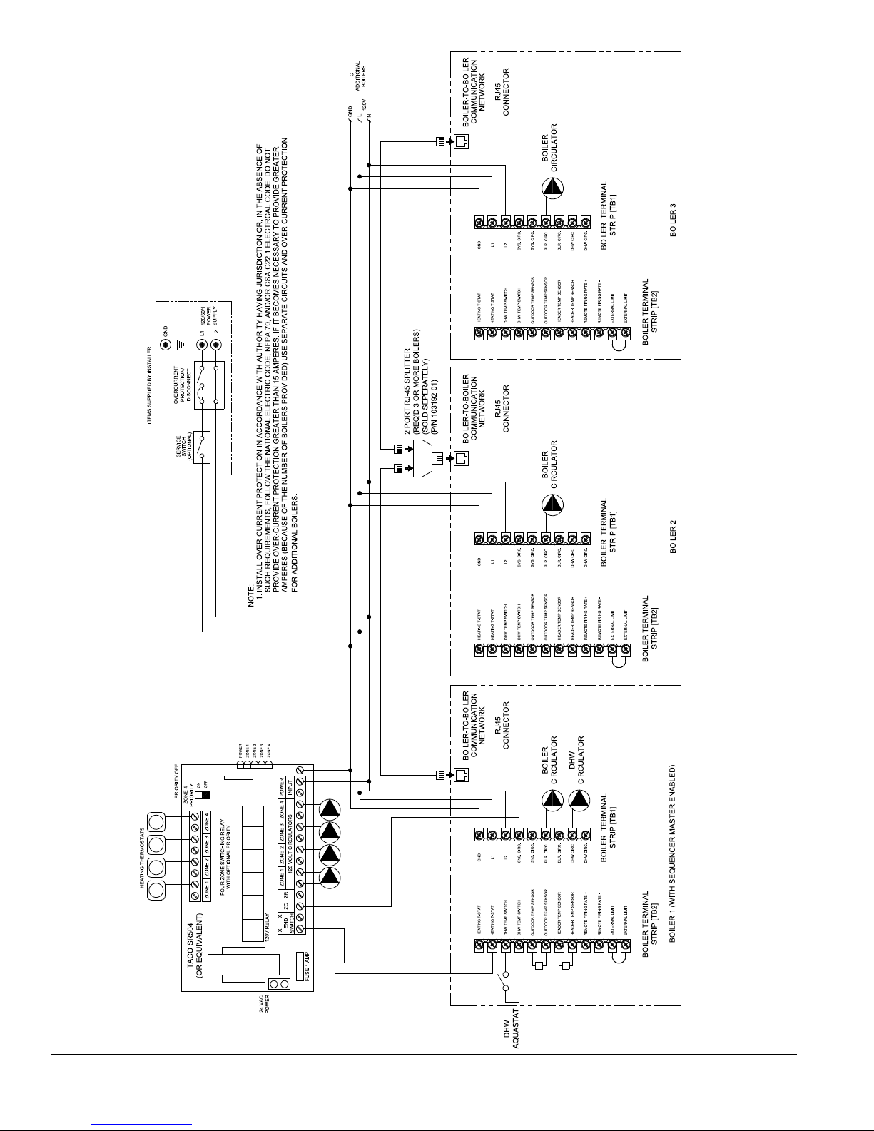
Figure 46: Multiple Boiler Wiring Diagram
Internal Sage2.1 Multiple Boiler Control Sequencer
(Three Boilers Shown, Typical Connections for up to Eight Boilers)
VIII. Electrical (continued)
78 103448-02 - 6/13
Page 79
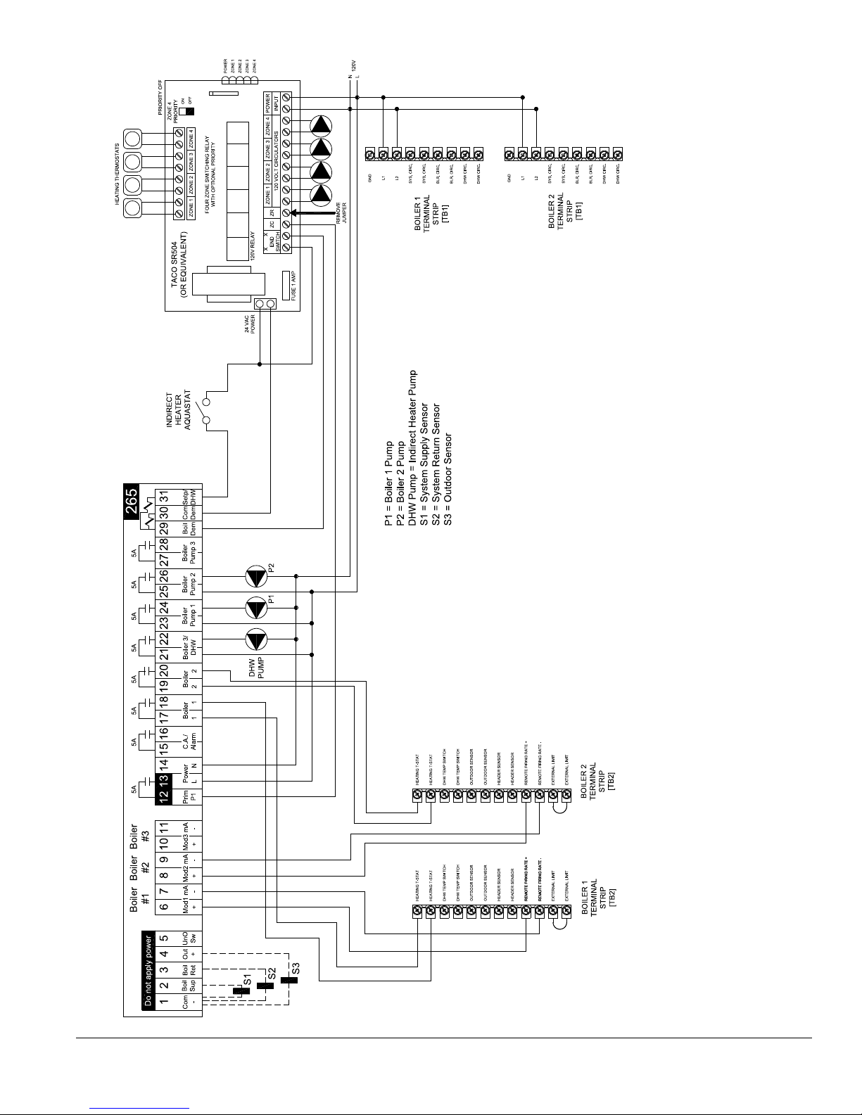
VIII. Electrical (continued)
Sequence of Operation
Tekmar 265 Based Control System (or equal)
Figure 47A: Multiple Boiler Wiring Diagram w/Tekmar 265 Control
The Tekmar 265 Control (or equal) can control up to three (3) boilers and an Indirect Water Heater. When a call for heat is received by the Tekmar 265 Control, the control
will re either one or more boilers in either parallel or sequential ring mode to establish a required reset water temperature in the system supply main based on outdoor
temperature. The boilers will modulate based on an Analog communication signal established between the Tekmar 265 Control and each boiler’s Sage2.1™ Control. The
boiler(s) and system supply water temperature will be reset together to maintain the input that is needed to the system. When a call for Indirect Hot Water is generated to the
Tekmar 265, the control will de-energize the zone pump control (ZC terminal), energize the Indirect pump and modulate the boiler ring to establish a setpoint temperature in
the main for the Indirect Heater using Priority. The Tekmar 265 also controls each boiler’s pump and a post purge of leftover temperature in the boilers will occur at the end of
the call for Indirect Hot Water.
103448-02 - 6/13 79
Page 80
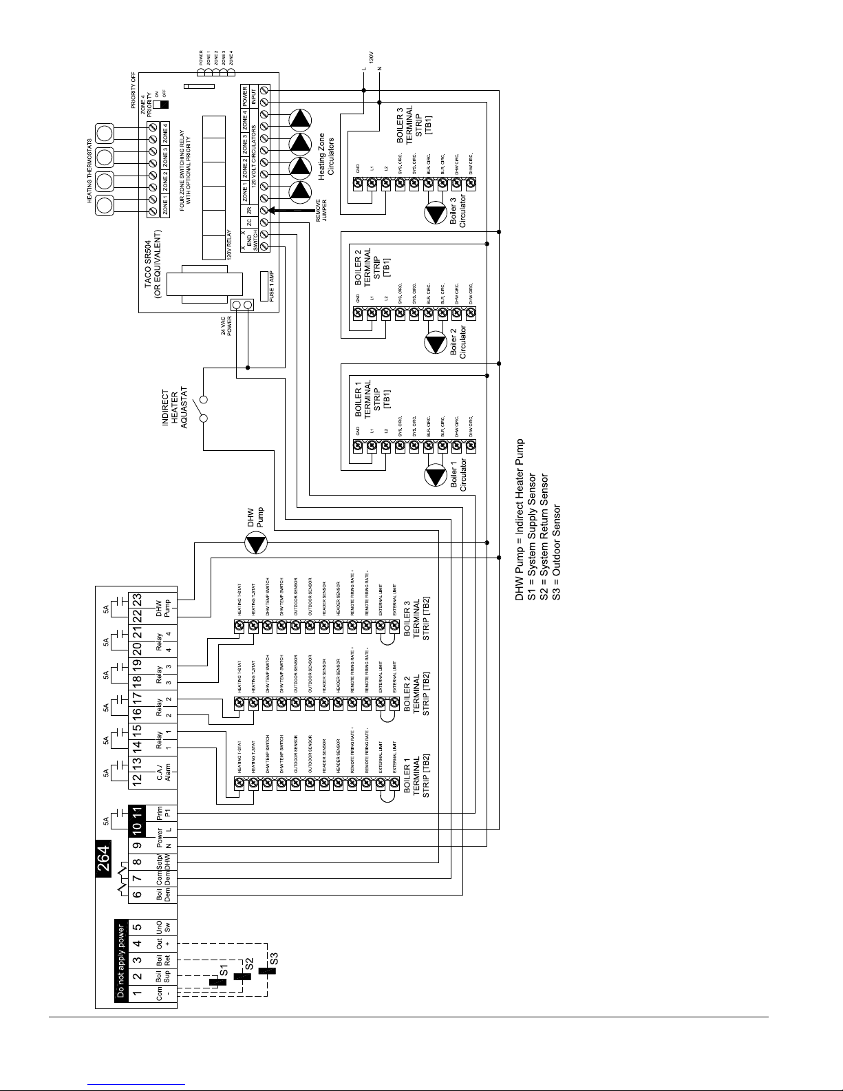
Sequence of Operation
Tekmar 264 Based Control System (or equal)
Figure 47B: Multiple Boiler Wiring Diagram w/Tekmar 264 Control
VIII. Electrical (continued)
80 103448-02 - 6/13
The Tekmar 264 Control (or equal) can control up to four (4) boilers and an Indirect Water Heater by utilizing stage ring. When a call for heat is received by the Tekmar 264
Control, the control will re either one or more boilers in sequential ring mode to establish a required reset water temperature in the system supply main based on outdoor
temperature. The boilers will modulate on their own based on each boiler’s Sage2.1™ Control and will target a setpoint temperature to supply enough input to the system
main to satisfy the desired reset water temperature in the main established by the Tekmar 264 Control. When a call for Indirect Hot Water is generated to the Tekmar 264,
the control will de-energize the zone pump control (ZC terminal), energize the Indirect pump and sequentially re the boilers to establish a setpoint temperature in the main
for the Indirect Heater using Priority. The Tekmar 264 Control will disable the stage ring and post purge the Indirect Pump to reduce the temperature in the Supply Main
near the end of the Indirect Mode to a point where it will need to be when it changes back to Space Heating Mode. The Tekmar 264 Control also has the ability to rotate the
lead-lag ring of the boilers to establish equal operating time for each boiler stage.
Page 81
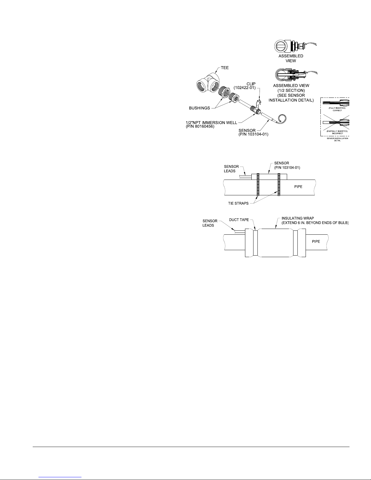
VIII. Electrical (continued)
G. Multiple Boiler Operating Information
1. Required Equipment and Setup
a. Header Sensor (p/n 103104-01)
A header sensor must be installed and wired
to the Master Sequencer “enabled” Sage2.1
Controller. The header sensor is installed on the
common system piping and provides blended
temperature information to the Sequence Master.
Refer to piping diagram Figures 40A and 41A
for installation location and Figure 48 or 49 for
installation detail.
b. RJ45 Splitters (P/N 103192-01)
RJ45 Splitters are required for installing
communications between three or more boilers.
When two boilers are connected the splitter is not
required.
c. Ethernet Cables
Ethernet cables are used to connect the boiler
network together. These are standard “straight
through” cables that can be purchased at
electrical distributors.
Alternately, the network can be wired together
by simply wiring terminal J3, Modbus 2,
terminals A, B and V- between each boiler.
Refer to Figures 43 and 44 terminal J3 for wiring
location.
Figure 48: Recommended “Immersion”
Type Header Sensor Installation Detail
Note: The “Strap-On” type sensor must be mounted to
the top side of a horizontal section of pipe as indicated in
Figures 40A and 41A.
Figure 49: Alternate “Strap-On” Type Header
Sensor Installation Detail
103448-02 - 6/13 81
Page 82
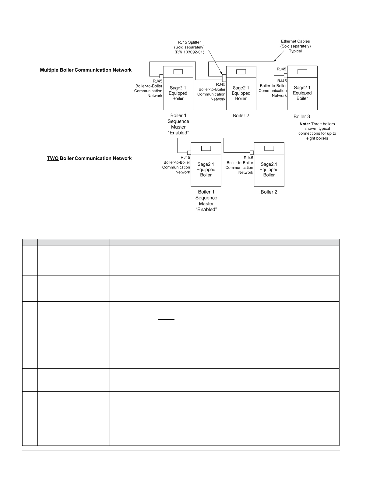
VIII. Electrical (continued)
Figure 50: RJ45 Splitter Installation Detail
d. Multiple Boiler Setup
Step Description Comments
Wire the header sensor to low voltage terminal strip terminals “Header sensor”.
Install and wire the Header
1
Sensor
Install Ethernet Cables
2
between boilers
3 Apply Power to All Boilers
Set Unique Boiler
4
Addresses
5 Enable 1 Boiler Master
6 Power Down All Boilers
Power Up Master
7
Sequencer
“Enabled” Boiler First
This step can not be skipped. The Sequence Master can not be “enabled”unless a Header
Sensor is installed.
Standard Ethernet type cables with RJ45 connectors are “plugged in” to the Boiler-to-Boiler
Communication Network connection located on the side of the boiler. When more than two
boilers are connected an RJ45 splitter may be used to connect the boilers. Refer to Figure
50.
Assign all boilers a unique Boiler Address using any number from 1 through 8.
When two boiler’s addresses are the same undesirable simultaneous operation occurs.
Enable only one Control’s Sequencer Master.
When more than one Sequencer Master is enable erratic behavior will result.
NOTE
WARNING
WARNING
8 Power Up Other Boilers
From the Home Screen of the Control with the Master Sequencer “enabled”, select the Status
button. The Sequencer display shows the boiler address of the communicating boilers.
9 Conrm Communication
Additionally, from the “Home” screen select the “Detail” button and then the “Networked
Boilers” buttons to view boiler communication status.
If a boiler is not shown, check Ethernet cable connections and conrm all boilers have unique
addresses.
82 103448-02 - 6/13
Page 83
IX. System Start-up
A. Verify that the venting, water piping, gas piping and
electrical system are installed properly. Verify that the
boiler condensate trap is lled with water. Refer to
installation instructions contained in this manual.
B. Conrm all electrical, water and gas supplies are turned
off at the source and that vent is clear of obstructions.
C. Conrm that all manual shut-off gas valves between
the boiler and gas source are closed.
WARNING
Completely read, understand and follow all
instructions in this manual before attempting
start up.
D. If not already done, ush the system to remove
sediment, ux and traces of boiler additives. This must
be done with the boiler isolated from the system. Fill
entire heating system with water meeting the following
requirements:
NOTICE
pH between 7.5 and 9.5.
If system contains aluminum components, pH
must be less than 8.5
Total Dissolved Solids - less than 2500 PPM
Hardness - 3 to 9 grains/gallon.
Pressurize the system to at least 12 PSI. Purge air from
the system.
2. Alpine gas valves have inlet and outlet pressure
taps with built-in shut off screw. Turn each
screw from fully closed position three to four
turns counterclockwise to open taps. Connect
manometers to pressure taps on gas valve.
NOTICE
If it is required to perform a long term pressure
test of the hydronic system, the boiler should
rst be isolated to avoid a pressure loss due to
the escape of air trapped in the boiler.
To perform a long term pressure test including
the boiler, ALL trapped air must rst be removed
from the boiler.
A loss of pressure during such a test, with no
visible water leakage, is an indication that the
boiler contained trapped air.
3. Temporarily turn off all other gas-red appliances.
4. Turn on gas supply to the boiler gas piping.
5. Open the eld installed manual gas shut-off valve
located upstream of the gas valve on the boiler.
6. Conrm that the supply pressure to the gas valve is
14 in. w.c. or less. Refer to Table 24 for minimum
supply pressure.
7. Using soap solution, or similar non-combustible
solution, electronic leak detector or other approved
method. Check that boiler gas piping valves, and
all other components are leak free. Eliminate any
leaks.
WARNING
The maximum operating pressure of this boiler is
30 psig, 50 psig, 80 psig or 100 psig depending
on the model and relief valve option selected.
Never exceed these pressures. Do not plug or
change safety relief valve.
E. Conrm that the boiler and system have no water
leaks.
Do not use matches, candles, open ames or
other ignition source to check for leaks.
8. Purge gas line of air.
G. Operating Instructions
Start the boiler using the lighting instructions, see
Figure 51. After the boiler is powered up, it should go
through the following sequence. Refer to Section X,
“Operation” to locate and view sequence status.
DANGER
F. Prepare to check operation.
1. Obtain gas heating value (in Btu per cubic foot)
from gas supplier.
103448-02 - 6/13 83
Page 84
IX. System Start-up (continued)
Alpine™ Series Lighting and Operating Instructions
84 103448-02 - 6/13
Figure 51: Lighting Instructions
Page 85
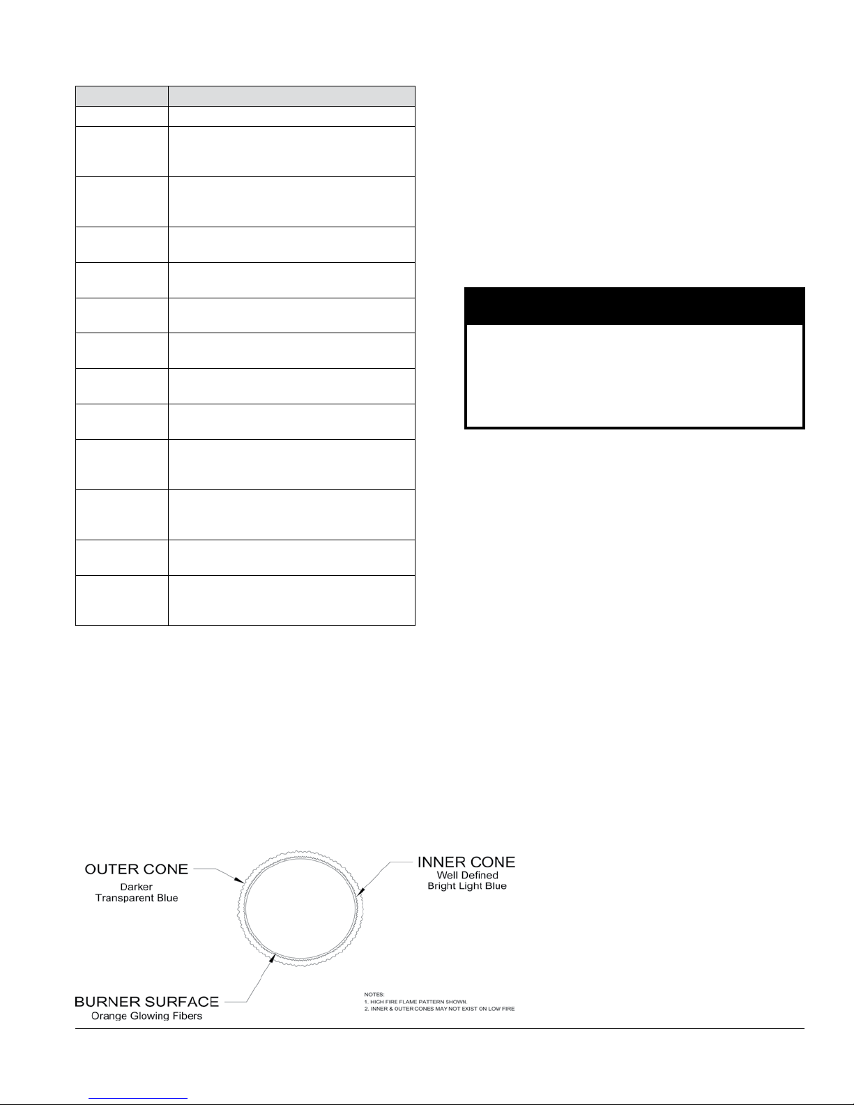
IX. System Start-up (continued)
Status Control Action
Initiate Power-up
This state is entered when a delay is
Standby Delay
Standby
Safe Startup
Drive Purge
Prepurge
Drive Light-off
Pre-ignition
Test
Pre-ignition
Direct
Ignition
Running
Postpurge
Lockout
needed before allowing the burner control
to be available and for sensor errors.
Boiler is not ring. There is no call for
heat or there is a call for heat and the
temperature is greater than setpoint.
Tests ame circuit then checks for ame
signal.
Driving blower to purge rate setting and
waiting for the proper fan feedback.
Purges the combustion chamber for the
10 second purge time.
Driving blower to light-off rate setting and
waiting for the proper fan feedback.
Tests the safety relay and veries that
downstream contacts are off.
Energizes the igniter and checks for
ame.
Opens main fuel valve and attempts
to ignite the main fuel directly from the
ignition source.
Normal boiler operation. Modulation rate
depends on temperature and setpoint
selections and modulating control action.
Purges the combustion chamber for the
30 second purge time.
Prevents system from running due to a
detected problem and records fault in
Lockout History.
H. Purge Air From Gas Train
Upon initial start-up, the gas train will be lled with air.
Even if the gas line has been completely purged of air,
it may take several tries for ignition before a ame is
established. If more than 5 tries for ignition are needed,
it will be necessary to press the reset button to restart
the boiler. Once a ame has been established for the
rst time, subsequent calls for burner operation should
result in a ame on the rst try.
I. Check Burner Flame
Inspect the ame visible through the window. On high
re the ame should be stable and mostly blue (Figure
52). No yellow tipping should be present; however,
intermittent ecks of yellow and orange in the ame are
normal.
J. Check Gas Inlet Pressure
Check the inlet pressure and adjust if necessary. Verify
that the inlet pressure is between the upper and lower
limits shown on the rating plate with all gas appliances
on and off.
WARNING
The outlet pressure for the gas valve has been
factory set and requires no eld adjustment. This
setting is satisfactory for both natural gas and
propane. Attempting to adjust the outlet pressure
may result in damage to the gas valve and cause
property damage, personal injury or loss of life.
K. For LP Gas, perform procedure as described in
Paragraph R “Field Conversion From Natural Gas to LP
Gas” before starting Paragraph L “Checking/Adjusting
Gas Input Rate”.
For natural gas, proceed to Paragraph L “Checking/
Adjusting Gas Input Rate”.
L. Checking / Adjusting Gas Input Rate
1. Turn off gas supply to all appliances other than gas-
red boiler.
2. Light main burner by adjusting thermostat to highest
setting.
3. Clock gas meter for at least two (2) revolutions
of the dial typically labeled ½ or 1 cubic foot per
revolution on a typical gas meter.
4. Determine gas ow rate in Cubic Feet per Hour
based on elapsed time for two revolutions.
Example:
Using a meter with dial labeled 1 cubic foot per
revolution, measured time is 72 Seconds for (2)
Revolutions, i.e. 36 seconds per 1 cubic foot.
Calculate hourly gas ow rate:
3600 sec/hr ÷ 36 sec/cu ft = 100 cu ft/hr
103448-02 - 6/13 85
Figure 52: Burner Flame
Page 86
IX. System Start-up (continued)
5. Obtain gas-heating value (Btu per cubic foot) from
gas supplier.
6. Multiply hourly gas ow rate by gas heating value
to determine the boiler input rate, BTU/hr
Example:
Natural gas heating value provided by local gas
utility is 1050 Btu per cubic foot.
Measured and calculated hourly gas ow rate is 100
cu ft/hr.
Measured boiler input rate is:
100 cu ft/hr x 1050 BTU/ cu ft = 105, 000 BTU/hr
7. Compare measured input rate to input rate value
stated on rating label. Strive to adjust the boiler
input rate within 88% to 100% of the value listed on
the boiler rating label.
8. If measured input is too high, reduce input rate by
rotating gas valve throttle screw clockwise (see
Figure 53) in ¼ turn increments and checking the
rate after every adjustment until the measured input
rate value falls within 88% to 100% of the value
listed on the boiler rating label.
9. If measured input is too low, increase input rate by
rotating gas valve throttle screw counterclockwise
(see Figure 53) in ¼ turn increments and checking
the rate after every adjustment until the measured
input rate value falls within 88% to 100% of the
value listed on the boiler rating label.
10. Once the boiler input rate adjusted/conrmed,
recheck main burner ame and perform combustion
test as described below (see Paragraph M “ Perform
Combustion Test”).
11. Upon completion, return other gas-red appliances
to previous condition of use.
M. Perform Combustion Test
Boilers are equipped with Flue Temperature Sensor
installed into:
• Flue sensor port of boiler CPVC/PVC two-pipe
vent system connector (oor standing build) -
See Figures 6 and 17.
• Flue sensor port of vent elbow, located inside air
box behind access panel (wall hung build) - see
Figure 7B.
• Flue sensor port of boiler concentric vent collar
(oor standing build) - see Figure 18.
Remove Flue Temperature Sensor and insert the
analyzer probe through Flue Temperature Sensor
silicon cap opening, or if required, remove also the Flue
Temperature Sensor silicon cap and insert the analyzer
probe directly into ue sensor port. Reinstall the sensor
and the cap upon combustion testing completion.
Check CO
(or O2) and CO at both high and low re.
2
The boiler may be locked into high or low re as
follows:
1. To lock the boiler in high re, enter the Manual
Control screen by rst entering the Adjust screen.
To access the Adjust screen, touch the Adjust button,
then Login using the contractor password “076”.
Press Save and then select the adjust button. Enter
the Manual Control button and select “High”.
Allow the boiler to operate for approximately 5
minutes before taking combustion readings.
2. To lock the boiler in low re select “Low” from
the Manual Control screen. Allow the boiler to
operate for approximately 5 minutes before taking
combustion readings.
3. Normal modulation of the boiler will only occur
after the “Auto” button is selected in the Manual
Control screen.
Typical CO2 values for natural gas are shown in Table
26.
Typical CO
values for LP gas are shown in Table 27.
2
If actual combustion readings are outside of typical
values shown, contact factory for assistance.
WARNING
Each Alpine Series boiler is tested at the factory
and adjustments to the air fuel mixture are
normally not necessary. Improper gas valve or
mixture adjustments could result in property
damage, personal injury, or loss of life.
Table 26: Typical Combustion Values, Natural Gas
Boiler
Model
ALP080B
ALP105B
ALP150B
ALP210B
ALP285B
ALP399
% CO
9.9 - 8.2
(High Fire)
9.9 - 7.9
(Low Fire)
Altitude Range
0 - 7000 Ft.
% O2 Range CO, PPM
2
3.5 - 6.5
(High Fire)
3.5 - 7.0
(Low Fire)
Less than
100 PPM
86 103448-02 - 6/13
Page 87
IX. System Start-up (continued)
Table 27: Typical Combustion Values, LP Gas
Boiler
Model
ALP080B
ALP105B
ALP150B
ALP210B
ALP285B
ALP399
% CO
11.4 - 9.5
(High Fire)
11.4 - 9.1
(Low Fire)
Altitude Range
0 - 7000 Ft.
% O2 Range CO, PPM
2
3.5 - 6.5
(High Fire)
3.5 - 7.0
(Low Fire)
Less than
100 PPM
WARNING
These instructions include a procedure for
adjusting the air-fuel mixture on this boiler.
This procedure requires a combustion analyzer
to measure the CO2 (or Oxygen) and Carbon
Monoxide (CO) levels in ue gas. Adjusting the
air-fuel mixture without a proper combustion
analyzer could result in unreliable boiler operation,
personal injury, or death due to carbon monoxide
poisoning.
4. While the burner is at high re adjust the throttle
as needed to obtain the CO
(or O2) settings shown
2
in the Table 26 (for natural gas) or Table 27 (for LP
gas):
• To reduce the CO2 (increase the O2) turn the
throttle clockwise
• To increase the CO2 (reduce the O2) turn the
throttle counter-clockwise
Make adjustments in increments of 1/8 to 1/4 turn
and allow the boiler at least a minute to respond to
each adjustment before making another. In general,
the CO level will be at its lowest somewhere in the
CO2 range shown in this table.
5. Verify that the gas inlet pressure is between the
upper and lower limits shown in Table 24 with all
gas appliances (including the converted boiler) both
on and off.
6. To lock the boiler in low re, select “Low” from
manual control screen. If measured % O2 on LF,
is out of spec (see Table 26 or 27), then turn offset
screw clockwise (see Figure 53) to lower % O2 or
vice versa.
WARNING
Offset screw on each Alpine Series boiler is
adjusted at the factory to the specication. DO
NOT touch the offset screw if measured 02 on Low
Fire is in the spec (see Table 26 or 27).
7. If the boiler is converted from natural to LP gas then
use a label sheet which is provided with the boiler
for conversions from natural to LP gas. Otherwise
skip this Step and proceed to Step 8. Once
conversion is completed, apply labels as follows:
• Apply the “Rating Plate Label” adjacent to the
rating plate.
• Apply the “Gas Valve Label” to a conspicuous
area on the gas valve.
• Apply the “Boiler Conversion Label” to a
conspicuous surface on, or adjacent to, the outer
boiler jacket. Fill in the date of the conversion
and the name and address of the company
making the conversion with a permanent marker.
8. Install Flue Temperature Sensor into:
• Flue sensor port of boiler CPVC/PVC two-pipe
vent system connector (oor standing build) -
See Figures 6 and 17.
• Flue sensor port of vent elbow, located inside air
box behind access panel (wall hung build) - see
Figure 7B.
• Flue sensor port of boiler concentric vent collar
(oor standing build) - see Figure 18.
9. Install Access Panel/Gasket Assembly as shown in
Figure 2E.
WARNING
Access Panel must be installed after the vent
pipe is fully secured into the vent elbow. Failure
to properly secure the vent into the elbow with
clamp, could lead to property damage, personal
injury or loss of life.
N. Test External Limits
Test any external limits or other controls in accordance
with the manufacturer’s instructions.
O. Check Thermostat Operation
Verify that the boiler starts and stops in response to
calls for heat from the heating thermostat and indirect
water heater thermostat. Make sure that the appropriate
circulators also start and stop in response to the
thermostats.
P. Adjust Supply Water Temperature
As shipped, the heating set point supply temperature is
set to 180°F and, indirect water heater set point supply
temperature is set to 170°F. If necessary, adjust these to
the appropriate settings for the type of system to which
this boiler is connected. See Section X “Operation”
(parameter Table on page 107) of this manual for
information on how to do this.
103448-02 - 6/13 87
Page 88
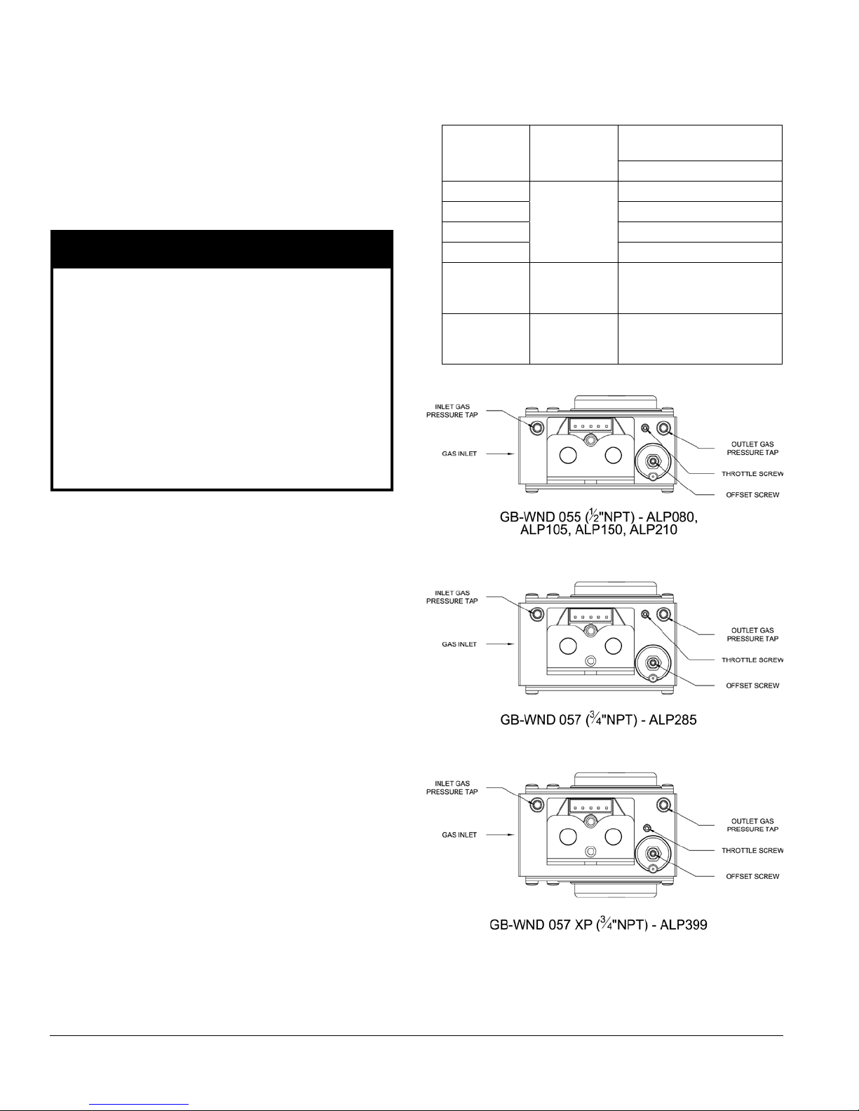
IX. System Start-up (continued)
Q. Adjust Thermostats
Adjust the heating and indirect water heater thermostats
to their nal set points.
R. Field Conversion From Natural Gas to LP Gas
Alpine Series boilers are factory shipped as Natural Gas
builds. Follow steps below for eld conversion from
Natural Gas to LP Gas.
WARNING
This conversion should be performed by a
qualied service agency in accordance with the
manufacturer’s instructions and all applicable
codes and requirements of the authority
having jurisdiction. If the information in these
instructions is not followed exactly, a re, an
explosion or production of carbon monoxide may
result causing property damage, personal injury,
or loss of life. The qualied service agency is
responsible for proper conversion of these boilers.
The conversion is not proper and complete until
the operation of the converted boiler is checked
as specied in this manual.
Table 28: Number of Clockwise Throttle Screw
Turns for LP Conversion
Throttle Screw Turns at
Boiler Model Gas Valve
ALP080B
ALP105B 4
ALP150B 3¼
ALP210B 4
ALP285B
ALP399
Dungs
GB-055
(½” NPT)
Dungs
GB-057
(¾” NPT)
Dungs
GB-057 HO
(¾” NPT)
Altitude Range
0 - 7000 Ft.
2¾
4½
1¾
1. All Alpine boiler models can be converted from
Natural Gas to LP Gas.
2. Conversion of Alpine Series boilers from one fuel
to another is accomplished using the throttle screw
on the gas valve. Figure 53 shows the location of
the throttle screw on the Dungs valve. Locate the
throttle on the boiler being converted.
3. If conversion is being made on a new installation,
install the boiler in accordance with the installation
instructions supplied with the boiler. If an installed
boiler is being converted, connect the new gas
supply to the boiler, check for gas leaks, and purge
the gas line up to the boiler in accordance with
the National Fuel Gas Code (ANSI Z223.1) or the
requirements of the authority having jurisdiction.
4. Before attempting to start the boiler, make the
number of turns to the throttle screw called for in
Table 28.
5. Attempt to start the boiler using the lighting
instructions located inside the lower front cover of
the boiler. If the boiler does not light on the rst
try for ignition, allow to boiler to make at least
four more attempts to light. If boiler still does not
light, turn the throttle counter clockwise in 1/4 turn
increments, allowing the boiler to make at least
three tries for ignition at each setting, until the boiler
lights.
Figure 53: Dungs Gas Valve Detail
6. Go back to Paragraph L “Checking/Adjusting Gas
Input Rate” and Paragraph M “Perform Combustion
Test”.
88 103448-02 - 6/13
Page 89
IX. System Start-up (continued)
WARNING
The throttle adjustments shown in Table 28 are approximate. The nal throttle setting must be found using
a combustion analyzer. Leaving the boiler in operation with a CO level in excess of the value shown in
Table 27 could result in injury or death from carbon monoxide poisoning.
NOTICE
If the throttle is very far out of adjustment on the “rich” (counter-clockwise) side, the boiler burner may be
running at 0% Excess Air or even with air deciency.
At 0% Excess Air the CO2 readings will be either 11.9% CO2 for Natural Gas or 13.8% CO2 for LP Gas (O2 will
be 0%) and CO level will be extremely high (well over 1000 PPM).
If the burner operates with air deciency, the following phenomena may be observed:
% CO2 will actually drop (% O2 will increase) as the throttle is turned counterclockwise
% CO2 will actually increase (% O2 will drop) as the throttle is turned clockwise
If the boiler appears to operate with air deciency, turn the throttle clockwise to increase the amount of
Excess Air to the burner.
As the throttle is turned clockwise, the CO2 level will rise, eventually peaking @ 11.8% or 13.8%, depending
of the type of gas being used, before falling (conversely, O2 level will drop to 0% before rising). After this
happens, continue turning the throttle clockwise, until CO2 level drops (or O2 level increases) to the values
shown in Table 26 or Table 27.
WARNING
The pressure regulator (offset screw) has been factory set using precision instruments and must never
be adjusted in the eld unnecessarily. The gas valve outlet pressure is the same for both natural gas and
propane. Make sure that all adjustments are made with the throttle, not the pressure regulator. Attempting
to adjust the pressure regulator unnecessarily, may cause property damage, personal injury or loss of life.
103448-02 - 6/13 89
Page 90
IX. System Start-up (continued)
S. Controls Startup Check List
The Control is factory programmed with default parameters. Before operating the boiler, these parameters must be checked
and adjusted as necessary to conform to the site requirements. Follow the steps below, making selections and adjustments as
necessary to ensure optimal boiler operation.
No. Title Terminal Description
1 & 2
2 & 3 Is an Indirect Water Heater (IWH) providing a boiler heat demand?
5 & 6
1
From the Home Screen press the Adjust button and login to access the adjust mode screens (if required, refer to X. Operation
Section, “Entering Adjustment Mode” Paragraph G, 1 for login instructions). The following parameters should be reviewed:
No. Menu Parameter Description
2
3
4
5
6
7
8 DHW
9
10 Sequencer Master Slave
Check
Wiring
System
Setup
Modulation
Setup
Pump
Setup
Contractor
Setup
Manual
Control
Central
Heat
Remote
4-20mA
7 & 8 Is a header sensor used? If yes, refer to step 10 below to activate this feature.
9 & 10
11 & 12 Is an External Limit used? Remember to remove factory-installed jumper.
LWCO Plug Is a LWCO required? Check installation of the LWCO.
Warm Weather
Shutdown
Warm Weather
Shutdown Setpoint
Boiler Type
System Pump
Boiler Pump
Domestic Pump
Contractor Name
Address
Phone
Manual Speed
Control
Setpoint Ensure Setpoint, (ring rate target temperature) is correct for you type of radiation.
Setback
Setpoint
Setpoint Ensure Setpoint, (ring rate target temperature) is suitable for the IWH requirements.
Setback
Setpoint
Modulation Source
Setpoint Source Set to 4-20mA when a Energy Management system is sending a “remote” setpoint.
Is the heating thermostat connected? Insure this is “dry”, non-powered input.
Is an Outdoor Air sensor used? If no, select outdoor sensor type “not installed” under
system menu.
Is a Remote 4-20mA required for a Energy Management System or external multiple
boiler control? If used see step 9 below to activate this input.
Selecting “Enable” will restrict boiler start during warm weather (only if an outdoor air
temperature sensor is installed).
Use this setting to adjust the temperature that the WWSD function will shut boiler off.
WARNING
Conrm that the correct boiler model is shown. Stop installation and contact factory if
the wrong boiler model is shown.
Ensure that the pump parameter selections are correct for your heating system. Refer
to Paragraph G. Adjusting Parameters, Pump Setup Menu for additional information.
Enter your contact information, name, address, and phone number on this screen.
In the event of a fault or the need to adjust a setting the display will direct the
homeowner to you.
Use the “High and “Low” options to force the boiler to high re and low re for
combustion testing.
Check the setting for the central heat setpoint when the T-Stat “Sleep” or “Away”
Setback mode is entered (if EnviraCOM Setback thermostat is used).
Check the setting for the DHW setpoint when the T-Stat “Sleep” or “Away” Setback
mode is entered (if EnviraCOM Setback thermostat is used).
Set to 4-20mA when an external multiple boiler controller is connected to the system.
Refer to Sequencer Master Setup Section X, G if multiple boilers are installed at this
site.
90 103448-02 - 6/13
Page 91

X. Operation (A. Overview)
180 F
Boiler 1
Energy Save On
Max Efficiency On
Standby
i
Status
Help
Adjust
Detail
A. Overview
1. Sage 2.1 Controller
The Sage 2.1 Controller (Control) contains features and
capabilities which help improve heating system operation,
efficiency and home comfort. By including unique
capabilities, the Control can do more, with less eld
wiring, and fewer aftermarket controls and components
– improving the operation of both new and replacement
boiler installations.
2. Advanced Touch Screen Display
Home Screen
Boiler status and setup selections are available from an
easy to use, dual color, LCD Touch Screen Display. Over
one hundred helpful information screens are provide to
explain status information and setup functions. In the event
of a fault condition the user is guided by “blinking” touch
buttons to Help screens that explain the problem cause and
corrective action. Operation evaluation and problem-solving
is enhanced by historical capability including graphic trends,
lockout history records as well as boiler and circulator cycle
counts and run time hours.
3. Advanced Modulating Control
The Control modulates the boiler input by varying the fan
speed. As the fan speed increases, so does the amount of
fuel gas drawn into the blower. As a result, a fairly constant
air-fuel ratio is maintained across all inputs. The Control
determines the input needed by looking at both current and
recent differences between the measured temperature and
the setpoint temperature. As the measured temperature
approaches the setpoint temperature, the fan will slow down
and the input will drop. The Control also utilizes boiler
return water and ue gas temperatures to adjust fan speed.
4. Built-in Safety Control
The Control includes safety controls designed to ensure safe
and reliable operation. In addition to ame safety controls
the Control includes supply water temperature, differential
water temperature, and stack temperature safety limits and
stepped modulation responses. Boiler modulation is adjusted
when required to help avoid loss of boiler operation due
to exceeding limits. Additionally, the Control accepts the
optional eld installation of low water cut-off and auxiliary
safety limits.
5. Outdoor Air Reset
When selected the modulation rate setpoint is automatically
adjusted based on outside air temperature, time of day and
length of demand (boost) settings. Outdoor air “reset”
setpoint saves fuel by adjusting the water temperature of a
103448-02 - 6/13 91
heating boiler lower as the outside air temperature increases.
6. Warm Weather Shutdown (WWSD)
Some boilers are used primarily for heating buildings,
and the boilers can be automatically shutdown when
the outdoor air temperature is warm. When outside air
temperature is above the WWSD setpoint, this function
will shut down the boiler, boiler pump and/or the system
pump.
7. Domestic Hot Water Priority (DHWP)
Some boilers are used primarily for building space heating,
but also provide heat for the domestic hot water users.
When the outdoor temperature is warm, the outdoor reset
setpoint may drop lower than a desirable domestic hot
water temperature. Also, often it is required to quickly
recover the indirect water heater. When DHWP is
enabled, heating circulators are stopped, the domestic
circulator is started and the domestic hot water setpoint is
established in response to a domestic hot water demand.
Priority protection is provided to allow the heating loop
to be serviced again in the event of an excessively long
domestic hot water call for heat.
8. Energy Management System (EMS) Interface
The control accepts a 4-20mAdc input from the EMS
system for either direct modulation rate or setpoint.
9. Circulator Control
The Control may be used to sequence the domestic hot
water, boiler and system circulators. Service rated relay
outputs are wired to a line voltage terminal block for easy
eld connection. Simple parameter selections allow all
three pumps to respond properly to various hydronic
piping arrangements including either a boiler or primary
piped indirect water heater. Circulators are automatically
run for a 20 second exercise period after not being used
for longer than 7 days. Circulator exercise helps prevent
pump rotor seizing.
10. Multiple Boiler Sequencer Peer-To-Peer Network
The Control includes state-of-the-art modulating lead-
lag sequencer for up to eight (8) boilers capable of auto
rotation, outdoor reset and peer-to-peer communication.
The peer-peer network is truly “plug and play”.
Communication is activated by simply connecting a RJ45
ethernet cable between boilers. The Control provides
precise boiler coordination by sequencing boilers based
on both header water temperature and boiler modulation
rate. For example, the lead boiler can be congured to
start a lag boiler after operating at 50% modulation rate for
longer than an adjustable time. The boilers are modulated
in “unison” (parallel) modulation rate to ensure even heat
distribution
11. Modbus Communication Interface
A factory congured RS485 Modbus interface is available
for Energy Management System (EMS)monitoring when
not used for Multiple Boiler Sequencer Peer-To-Peer
Network. Consult factory if this interface must be used
in addition to the boiler Peer-to-Peer Network.
Page 92
X. Operation B. Supply Water Temperature Regulation (continued)
B. Supply Water Temperature Regulation
1. Priority Demand
The Control accepts a call for heat (demand) from
multiple places and responds according to it’s “Priority”.
When more than 1 demand is present the higher priority
demand is used to determine active boiler settings.
For example, when Domestic Hot Water (DHW) has
priority the setpoint, “Diff Above”, “Diff Below” and
pump settings are taken from DHW selections. Active
“Priority” is displayed on the “Boiler Status” screen.
Table 29: Priority
Status
Priority
1st Sequencer
2nd Domestic Hot
3rd Central Heat Central Heat call for heat is on and
4th Frost
5th Warm
6th Standby There is no demand detected.
2. Setpoint Purpose
The Control starts and stops the boiler and modulates
3. Central Heat Setpoint
Upon a Central Heat call for heat the setpoint is either
Screen
Display
Control
Water
Protection
Weather
Shutdown
(WWSD)
Boiler Responding to:
The boiler is connected to the peerto-peer network. The boiler accepts
demand from the Sequencer Master.
DHW call for heat is on and selected
as the priority demand. DHW is
always higher priority than Central
Heat. It also has higher priority than
the Sequencer Control when DHW
priority is “enabled” and “Boiler Piped”
IWH is selected.
there is no DHW demand or DHW
priority time has expired.
Frost Protection is active and there is
no other call for heat. Frost protection
will be a higher priority than Sequencer
Control if the Sequence Master has
no active call for heat.
WWSD is active and the boiler will
not respond to central heat demands.
DHW demand is not blocked by
WWSD.
the boiler input from minimum (MBH) to maximum
(MBH) in order to heat water up to the active setpoint.
The setpoint is determined by the priority (Central Heat
or Domestic Hot Water) and as described in the following
paragraphs.
the user entered Central Heat Setpoint or is automatically
adjusted by a thermostat’s “Sleep” or “Away” modes and/
or Outdoor Air Reset or a Energy Management System
(EMS) supplied 4-20mAdc setpoint.
4. Outdoor Air Reset
If an outdoor temperature sensor is connected to the boiler
and Outdoor Reset is enabled, the Central Heat setpoint
will automatically adjust downwards as the outdoor
temperature increases. When the water temperature is
properly matched to home heating needs there is minimal
chance of room air temperature overshoot. Excessive heat
is not sent to the room heating elements by “overheated”
(supply water temperature maintained too high a setting)
water. Reset control saves energy by reducing room
over heating, reducing boiler temperature & increasing
combustion efciency and reducing standby losses as a
boiler and system piping cool down to ambient following
room over heating.
5. Boost Time
When the Central Heat Setpoint is decreased by Outdoor
Air Reset settings the Boost function can be enabled to
increase the setpoint in the event that central heat demand
is not satised for longer than the Boost Time minutes.
The Boost feature increases the operating temperature
setpoint by 10°F every 20 minutes (eld adjustable) the
central heat demand is not satised. This process will
continue until heat demand is satised (indoor air is at
desired temperature). Once the heat demand is satised,
the operating setpoint reverts to the value determined by
the Outdoor Air Reset settings. If Boost Time is zero,
then the boost function is not used.
6. Domestic Hot Water (DHW) Setpoint
Upon a DHW call for heat the setpoint is either the user
entered DHW setpoint or the Thermostat’s “Sleep” or
“Away” DHW setpoint. The optimal value of this setpoint
is established based on the requirements of the indirect
water heater.
7. Domestic Hot Water Priority (DHWP)
When domestic hot water priority is selected and there
is a DHW call for heat, the system pump will be turned
off (when system pump parameter is set for “Central
Heat Optional Priority”) and the DHW pump will be
turned on. Additionally, if outdoor reset is active, the
active setpoint is adjusted to the DHW Setpoint. Priority
protection is provided to ensure central heat supply in
the case of excessively long DHW call for heat.
8. “Setback” Setpoints
User adjustable Thermostat “Sleep” or “Away” Setback
Setpoints are provided for both Central Heat and
DHW demands. The Setback setpoint is used when the
EnviraCOM thermostat is in “leave” or “sleep” modes.
When setback is “on” the thermostat setback setpoint
shifts the reset curve to save energy while the home is
in reduced room temperature mode. The Honeywell
VisionPro IAQ (part number TH9421C1004) is a
“setback” EnviraCOM enabled thermostat.
92 103448-02 - 6/13
Page 93

X. Operation C. Boiler Protection Features (continued)
C. Boiler Protection Features
1. Supply Water Temperature High Limit
The boiler is equipped with independent automatic reset
and a manual reset High Limit devices. The automatic
reset high limit is provided by a supply manifold mounted
Limit Device. The automatic high limit is set to 200°F.
The Control monitors a supply water temperature sensor
that is also mounted in the supply water manifold and
supplies an internal, manual reset high limit. If supply
water temperature exceeds 190°F, the control begins
to reduce the blower maximum speed setting. If the
temperature exceeds 200°F, a forced recycle results.
If the temperature exceeds 210°F, a manual reset hard
lockout results. Additionally, if the supply temperature
rises faster than the degrees Fahrenheit per second limit
a soft lockout is activated.
2. High Differential Temperature Limit
The Control monitors the temperature difference between
the return and supply sensors. If this difference exceeds
43°F the control begins to reduce the maximum blower
speed. If temperature difference exceeds 53°F a forced
boiler recycle results. If the temperature difference
exceeds 63°F the control will shut the unit down. The
unit will restart automatically once the temperature
difference has decreased and the minimum off time has
expired.
3. Low Water Cut Off (LWCO)
The Control shuts down the boiler when either the
supply water temperature is too high or supply to return
temperature differential temperature is too high. This
ensures the boiler is shutdown in the event of a low water
level or low water ow condition.
Some codes and jurisdiction may accept these integral
features instead of requiring a low water cutoff. ADHERE
TO ALL LOCAL CODE REQUIREMENTS. Contact
your local code inspector prior to installation. If required, a
LWCO four-position wire harness connection is provided
for an external LWCO kit (p/n 102097-01) to be added.
If the LWCO opens, the boiler will shut down and an
open limit indication and error code is provided. If the
limit installed is a manual reset type, it will need to be
reset before the boiler will operate.
4. Return Temperature Higher Than Supply Temperature
(Inversion Limit)
The Control monitors the supply and return temperature
sensors. If the return water temperature exceeds the
supply water temperature for longer than a limit time
delay the Control shuts down the boiler and delays
restart. If the inverted temperature is detected more than
ve times the boiler manual reset Hard Lockout is set.
This condition is the result of incorrectly attaching the
supply and return piping.
5. External Limit
An external limit control can be installed between
terminals 11 and 12 on the low voltage terminal strip.
Be sure to remove the jumper when adding an external
limit control to the system. If the external limit opens, the
boiler will shut down and an open limit indication and
error code is provided. If the limit installed is a manual
reset type, it will need to be reset before the boiler will
operate.
6. Boiler Mounted Limit Devices
The Control monitors individual limit devices: pressure
switch, high limit device, condensate level switch,
Thermal Link (ALP285 and ALP399), Burner Door
Thermostat with manual reset (ALP285 and ALP399),
low water cutoff (optional), fuel gas pressure switches
(optional) and external limit (optional). If any of these
limits opens, the boiler will shut down and an individual
open limit indication is provided.
7. Stack High Limit
The Control monitors the ue gas temperature sensor
located in the vent connector. If the ue temperature
exceeds 184°F, the control begins to reduce the maximum
blower speed. If the ue temperature exceeds 194°F, a
forced boiler recycle results. If the ue temperature
exceeds 204°F, the control activates a manual reset Hard
Lockout.
8. Ignition Failure
The Control monitors ignition using a burner mounted
ame sensor. In the event of an ignition failure, the
control retries (ALP080B through ALP399) 5 times and
then goes into soft lockout for one hour.
9. Central Heating System Frost Protection
When enabled, Frost Protection starts the boiler and
system pump and res the boiler when low outside air
and low supply water temperatures are sensed. The
Control provides the following control action when frost
protection is enabled:
Table 30: Frost Protection
Device
Started
Boiler &
System Pump
Boiler Supply Water < 38°F Supply Water > 50°F
Supply Water < 45°F
Start
Temperatures
Outside Air < 0°F
Stop
Temperatures
Outside Air > 4°F
Supply Water > 50°F
FROST PROTECTION NOTE
The Control helps provide freeze protection for the boiler
water. Boiler ue gas condensate drain is not protected from
freezing. Since the Control only controls the system and
boiler circulators individual zones are not protected. It is
recommended that the boiler be installed in a location that is
not exposed to freezing temperatures.
103448-02 - 6/13 93
Page 94

X. Operation D. Multiple Boiler Control Sequencer (continued)
D. Multiple Boiler Control Sequencer
1. “Plug & Play” Multiple Boiler Control Sequencer
When multiple boilers are installed, the Control’s
Sequencer may be used to coordinate and optimize the
operation of up to eight (8) boilers. Boilers are connected
into a “network” by simply “plugging in” standard
ethernet cables into each boiler’s “Boiler-To-Boiler
Communication” RJ45 connection.
2. Sequencer Master
A single Control is parameter selected to be the Sequencer
Master. The call for heat, outdoor and header sensors,
and common pumps are wired to the Sequencer Master
“enabled” Control.
3. Lead/Lag Sequencing & Equalized Run Time
One boiler is a “Lead” boiler . When demand is increasing,
the Lead boiler is the rst to start and the remaining
boilers are started in sequential order (1,2,3,…) until
the demand is satised. When demand is decreasing,
the boilers are stopped in reverse order with the Lead
boiler stopped last (…,3,2,1). To equalize the run time
the sequencer automatically rotates the Lead boiler after
24 hours of run time.
4. Improved Availability
The following features help improve the heat availability:
a. Backup Header Sensor: In the event of a header sensor
failure the lead boiler’s supply sensor is used by the
Sequence Master to control ring rate. This feature
allows continued coordinated sequencer control even
after a header sensor failure.
b. “Stand Alone” Operation Upon Sequence Master
Failure: If the Sequence Master Control is powered
down or disabled or if communication is lost
between boilers, individual boilers may be setup to
automatically resume control as a “stand alone” boiler.
c. Boiler Rate Adjustment: Each boiler continues to
monitor supply, return and ue gas temperatures and
modies the Sequence Master’s ring rate demand to
help avoid individual boiler faults, minimize boiler
cycling and provide heat to the building efciently.
d. Boiler Status Monitoring: The Sequence Master
monitors boiler lockout status and automatically skip
over disabled boilers when starting a new boiler.
5. Customized Sequences
Normally, boilers are started and stopped in numerical
order. However, custom sequences may be established
to optimize the heat delivery. For example, in order to
minimize boiler cycling, a large boiler may be selected
to run rst during winter months and then selected to
run last for the remainder of the year.
6. Multiple Demands
The Sequence Master responds to Central Heat, DHW
and frost protection demands similar to the stand alone
boiler. For example, when selected and DHW priority
is active, the sequence master uses DHW setpoint, “Diff
Above”, “Diff Below” and pump settings.
7. Shared or Isolated DHW Demand
When the Indirect Water Heater (IWH) parameter is set
to “Primary Piped” the Sequence Master sequences all
required boilers to satisfy the DHW setpoint (default 180
F). When “Boiler Piped” is selected only the individual
boiler, with the wired DHW demand and pump, res to
satisfy the DHW setpoint.
8. DHW Two boiler Start
When the Indirect Water Heater (IWH) parameter is set
to “Primary Piped” and the “DHW Two Boiler Start”
parameter is set to “Enabled” two boilers are started
without delay in response to a DHW call for heat. This
feature allows rapid recovery of large IWH’s and multiple
IWH’s.
9. Optimized Boiler Modulation
Boiler ring rate is managed to increase smoothly as
boilers are started. For example, when a second boiler is
started the initial ring rate is 100%/2 or 50%, when the
third boiler is started the ring rate starts at 200%/3 or
66%. After the initial start, the Sequence Master develops
a unison ring rate demand based on it’s setpoint and
sensed header temperature.
10. Innovative Condensing Boiler Control
During low loads, the Sequence Master limits ring rates
to a ‘Base Load Common Rate” to ensure peak operating
efciency. Lower ring rates boost efciency by helping
increase the amount of ue gas water vapor condensation.
The Control maintains a “Base Load Common Rate” until
the last lag boiler is started. At this point, the “Base Load
Common Rate” is released to allow boilers to modulated
as required to meet heat load.
11. Advanced Boiler Sequencing
After there is a Call For Heat input, both header water
temperature and boiler ring rate percent are used to start
and stop the networked boilers. The control starts and
stops boilers when the water temperature is outside the
user selected “Diff Above” and “Diff Below” settings.
Also, in order to minimize temperature deviations, the
control adjusts the number of boilers running based on
the ring rate. This combination allows the boilers to
anticipate slow load changes before they disrupt water
temperature yet still respond quickly to sudden load
changes. These special sequencer features help reduce
energy wasting system temperature swings and the
resulting unnecessary boiler cycling.
12. Stop All Boilers
All boilers are stopped without delay if the Call for Heat
input is removed or if the header temperature is higher
than 195°F (eld adjustable).
94 103448-02 - 6/13
Page 95
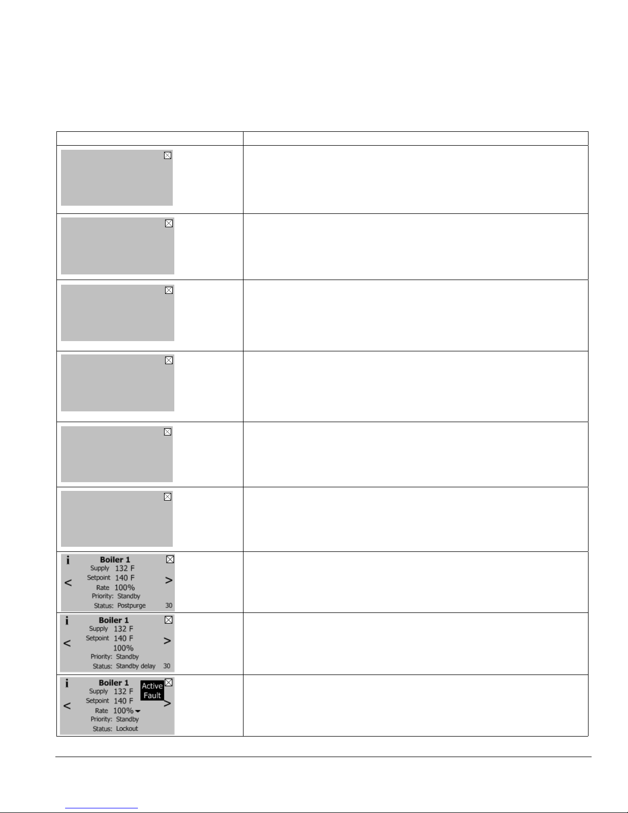
X. Operation E. Boiler Sequence Of Operation (continued)
i
i
i
i
i
i
E. Boiler Sequence of Operation
1. Normal Operation
Table 31: Boiler Sequence of Operation
Status Screen Display Description
Boiler 1
Supply
140 F
Setpoint
<
Rate
Priority:
Status:
140 F
0%
Standby
Standby
>
Priority:
Standby
Status:
Standby
(burner Off, circulator(s) Off)
Boiler is not ring and there is no call for heat, priority equals standby. The boiler
is ready to respond to a call for heat.
Boiler 1
Supply
140 F
Setpoint
<
<
Rate
Priority:
Status:
Boiler 1
Supply
Setpoint
Rate
Priority:
Status:
140 F
0%
Central Heat
Standby
132 F
140 F
98%
Central Heat
Prepurge 10
>
>
Priority:
Central Heat
Status:
Standby
Priority:
Central Heat
Status:
Prepurge
(burner Off, circulator(s) On)
Boiler is not ring. There is a Central Heat call for heat and the Supply temperature
is greater than setpoint minus the “Diff Below”.
When supply temperature drops burner demand continues with following Status
shown:
Safe Startup: Flame circuit is tested.
Drive purge: The blower is driven to the fan purge speed.
Prepurge: After the blower reaches the fan purge speed setting the 10
second combustion chamber purge is conducted.
Boiler 1
Supply
132 F
Setpoint
<
<
<
Rate
Priority:
Status:
Boiler 1
Supply
Setpoint
Rate
Priority:
Status:
Boiler 1
Supply
Setpoint
Rate
Priority:
Status:
140 F
89%
Central Heat
Direct Ignition
132 F
140 F
100%
Central Heat
Running
132 F
180 F
100%
Domestic Hot Water
Running
>
>
>
Priority:
Central Heat
Status:
Direct
ignition
Priority:
Central Heat
Status:
Running
Priority:
Domestic
Hot Water
Status:
Running
After purge time is complete the following Status is shown:
Drive light-off: The blower is driven to light-off rate.
Pre-Ignition Test: After the blower reaches light-off rate a safety relay test is
conducted.
Pre-ignition: Spark is energized and it is conrmed that no ame is present
Direct Ignition: Spark and Main fuel valve are energized.
(burner On, circulator(s) On)
After ame is proven normal boiler operation begins. Modulation rate depending
on temperature and setpoint selections and modulating control action.
If the Central Heat call for heat is active and a Domestic Hot Water (DHW) call for
heat received the DHW demand becomes the “priority” and the modulation rate,
setpoint, “Diff Above” and “Diff Below” are based on DHW settings.
Priority:
Standby
Status:
Post-purge
Priority:
Standby
Status:
Standby
Delay
Priority:
Standby
Status:
Lockout
103448-02 - 6/13 95
(burner Off, circulator(s) Off)
If there is no call for heat the main fuel valve is closed and the blower is driven
to the fan post-purge speed. After the blower reaches the fan post-purge speed
setting the 30 second combustion chamber purge is conducted.
This state is entered when a delay is needed before allowing the burner control to
be available. For example, when Anti-Short Cycle time is selected Standby delay
is entered after the Central Heat call for heat ends. Select “Help” button from the
“Home Screen” to determine the cause of the Standby Delay.
A lockout Status is entered to prevent the boiler from running due to a detected
problem. Select “Help” button from the “Home Screen” to determine the cause of
the Lockout. The last 10 Lockouts are recorded in the Lockout History.
Page 96
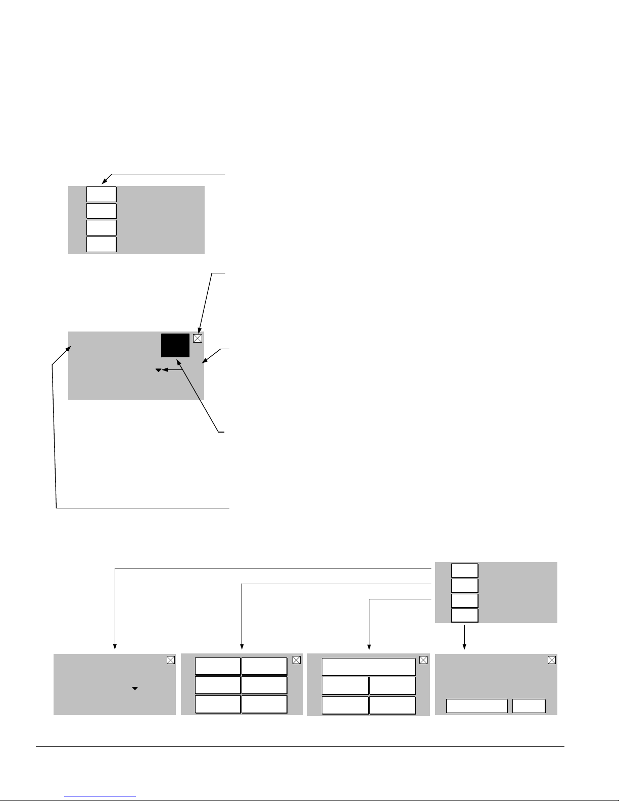
X. Operation E. Boiler Sequence Of Operation (continued)
2. Using The Display
The Control includes a touch screen LCD display. The user monitors and adjusts boiler operation by selecting screen
navigation “buttons” and symbols. The “Home Screen” and menu selections are shown below. When no selection is
made, while viewing any screen, the display reverts to the “Home Screen” after 4 minutes. The “Home Screen” displays
boiler temperature, boiler status and Efciency Information. “Energy Save On” indication appears when the outdoor reset
or setback features have lowered the Central Heat Setpoint based on outside air temperature measurement or time of day.
“Max Efciency On” appears when the boiler return temperature has been reduced low enough to cause energy saving
ue gas condensation.
Menu Button
Status
i
Detail
Help
Adjust
Boiler 1
180 F
Standby
Energy Save On
Max Efficiency On
Home Screen
The Home Screen Menu Buttons connect the displays four main display
groups; Status, Detail, Help and Adjustment Screens.
Close Symbol
The “Close” symbol returns to the display to previous menu or screen.
Repeatedly pressing the “Close” symbol will always return the display to the
“Home” screen.
i Active
<
Boiler 1
Supply
180 F
Setpoint
180 F
Rate
Priority:
Central Heat
Status: Standby
Fault
0%
Status Screen
>
Arrow Symbol
The “Arrow” symbol links together all screens in the selected group. For
example, repeated pressing the right “Arrow” symbol will rotate the display
around all the screens in the Status group. Using this feature the user can
review all the boiler status and adjustment mode screens.
Fault Symbols
“Active Fault” and “Rate Limit” symbols provide a link to the cause of a boiler
fault or firing rate limit. The first boiler status screen provides an overview of
boiler operation including fault status.
Information Symbol
“Information” symbol links most screens to screen content explanations. New
terminology used in status and adjustment screens are explained in plain words.
Home Screen
Status
i
Detail
Help
Adjust
Boiler 1
180 F
Standby
Energy Save On
Max Efficiency On
i
<
Boiler 1
Supply
Setpoint
180 F
180 F
0%
Rate
Priority:
Status: Standby
Status Screens
(see Figure 54)
Central Heat
>
Central Heat
Domestic
Hot Water
96 103448-02 - 6/13
Outdoor
Reset Curve
Detail Menu
(see Figure 55)
i
Active Faults
Lockout
History
Service
Contract
Help Menu
(see Figure 60)
Sequencer
Setup
Boiler Size
Setup
Warning! Only Qualified Technicians
Should Adjust Controls, Contact Your
Qualified Heating Professional
Improper settings or service create risk of
property damage, injury, or death.
Service Contact Adjust
Adjust Mode Screens
(see Figure 56)
Page 97
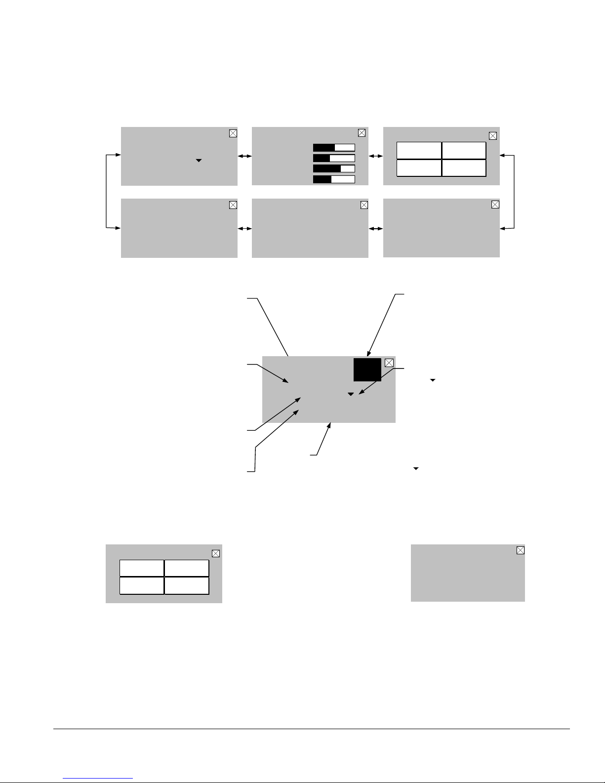
X. Operation F. Viewing Boiler Status (continued)
F. Viewing Boiler Status
1. Status Screens
Boiler Status screens are the primary boiler monitoring screens. The user may simply “walk” though boiler
operation by repeatedly selecting the right or left “arrow” symbol. These screens are accessed by selected the
“Status” button from the “Home” screen.
i
i
Boiler 1
Supply
Setpoint
Domestic Hot Water Off
180 F
180 F
0%
Rate
Priority:
Status: Standby
Heat Demand
Sequence Master Off
Frost Protection Off
Central Heat
Central Heat On
><
><
Supply:
measured supply water temperature. This is the
temperature being used to start/stop and fire boiler
when there is a call-for- heat.
Setpoint:
this is the active setpoint. This temperature is the
result of Outdoor Air Reset, Setback and Domestic
Hot Water (DHW) selections.
Rate:
The rate % value is equal to the actual fan speed
divided by the maximum fan speed.
Priority:
The selected Priority is shown. Available Priorities
are: Standby (no call for heat is present), Sequencer
Control, Central Heat, Domestic HW, Frost
Protection or Warm Weather Shutdown.
i
Pump Status/Cycles
i
Frost Protection On Exercise On
Status
Supply
180 F
Return
160 F
Stack
147 F
Rate
40 %
System On 98
Boiler On 23
DHW Off 0
><
><
Figure 54: Status Screens
i Active
<
Status:
Information found at the
bottom of the Status screen
and on the Home screen.
Table 31 shows each status
and the action the control
takes during the condition.
Boiler 1
Supply
180 F
Setpoint
180 F
Rate
Priority:
Central Heat
Status: Standby
Fault
0%
Trends
Flame
2.5 hour trend
Flame
5 minute trend
Boiler Cycles/Hours
i
Boiler Cycles
Run Time Hours
Supply / Return
Firing Rate
2000
800
><
><
Active fault:
A hard lockout will cause the active
fault indication to appear. When
visible the text becomes a screen link
to the “Help” Menu.
Rate Limit:
The “
>
of the Rate % when firing rate is
” symbol appears to the right
limited or overridden in any way.
During the start-up and shutdown
sequence it is normal for the rate to be
overridden by the purge and light-off
requirements. When a rate limit is the
result of boiler protection logic the
“
” symbol blinks and becomes a
screen link
Trends
Flame
2.5 hour trend
Flame
5 minute trend
Supply / Return
Firing Rate
Data Logging
Real time graphic trends allow users to observe process
changes over time providing valuable diagnostic information.
For example, ame current performance over start up
periods and varying loads can be an indication of gas supply
issues. Additionally, supply and return temperature dual
pen trends brings a focused look at heat exchanger and
pump performance. For example, studying a differential
temperature trend may indicate pump speed settings need
to be changed.
103448-02 - 6/13 97
Boiler Cycles/Hours
i
><
Boiler Cycles
Run Time Hours
2000
800
><
Cycles and Hours
Boiler cycles and hours are used to monitor the boilers
overall compatibility to the heating load. Excessive
cycling compared to run time hours may be an
indication of pumping, boiler sizing or adjustment
issues.
Page 98
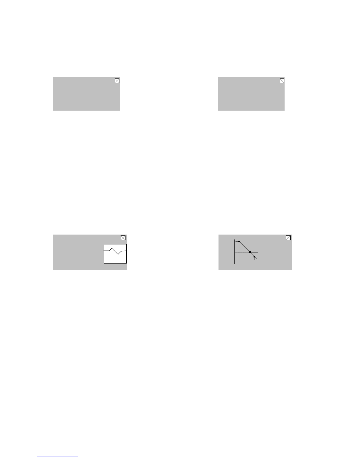
X. Operation F. Viewing Boiler Status (continued)
Central Heat
On Point - 7 F
Setpoint
Off Point +
5 F
Firing Rate 22%
Setpoint: Outdoor Reset
i
180 F
180 F
Supply
Outdoor Reset
Outside Air
W
a
t
e
r
180
130
110
0 70
i
Setpoint 164 F
Outside Air 16 F
Status: Enabled
1. Status Screens (continued)
Pump Status/Cycles
i
System On 98
Boiler On 23
DHW Off 0
Frost Protection On Exercise On
><
Pumping is a major part of any hydronic system. This
screen provides the status of the boiler’s demand to
connected pumps as well as the status of Frost Protection
and pump Exercise functions.
2. Detail Screens
Detail screens are accessed by selected the “Detail”
button from the “Home” screen and provide in depth
operating parameter status such as “On Point”, “Off
Point” and Setpoint Source information.
Heat Demand
i
Central Heat On
Domestic Hot Water Off
Sequence Master Off
Frost Protection Off
><
This screen provides the status of the boiler’s 4 possible
heat demands. When demand is off the Control has
not detected the call-for-heat.
Demand detail screens are provided for Central Heat
(shown), DHW and Sequencer demands.
98 103448-02 - 6/13
Outdoor Reset saves energy and improves home
comfort by adjusting boiler water temperature . This
screen presents the active reset curve. The curve shows
the relationship between outside air and outdoor reset
setpoint. The curve shown is adjustable by entering the
display’s adjust mode.
Figure 55: Detail Screens
Page 99
X. Operation F. Viewing Boiler Status (continued)
3. Multiple Boiler Sequencer Screens
When the Sequence Master is enabled the following screens are available:
The Sequencer Status screen is selected by “pressing” “Status” button from the “Home” screen when Sequence Master is enabled.
Header:
measured header water temperature.
This is the temperature being used to
start, stop and fire boiler when there is
a call-for-heat.
i
<
Setpoint:
this is the active setpoint. This
temperature is the result of Outdoor
Air Reset, Setback and Domestic Hot
Water (DHW) selections.
Networked Boiler Status:
Provides connected, start sequence and firing rate status information for all connected boiler addresses. The boiler number is
underlined if the boiler is running and blinks if the boiler has the start sequence in progress. For example the status for boiler
address 1 is provided as follows:
1 - Boiler 1 is connected to the network
1 - “Blinking underline” - boiler 1 is starting
1 - “Solid underline” - boiler 1 is running
The “Networked Boilers” screen is selected by “pressing” the “Detail” button from the “Home” screens and “pressing” Networked
Boilers” from the “Detail” screen.
Networked Boilers:
Sequencer
Header
Setpoint
Rate
Priority:
132 F
180 F
100%
>
Domestic Hot Water
1 ,2 ,3 ,4 ,5 ,6 ,7 ,8
Rate:
The rate % value is equal to the
Sequence Master demand to the
individual boiler. Actual boiler firing
rate is found on the individual boiler
status pages.
Priority:
The selected Sequencer Priority is
shown. Available Priorities are:
Standby (no call for heat is present),
Central Heat, Domestic Hot Water,
Frost Protection or Warm Weather
Shutdown.
Boiler Number:
Up to eight (8) boiler’s status is
shown
Lead Boiler:
Upon power up the lowest numbered
boiler becomes the lead boiler. The
lead boiler is the first to start and last
to stop. The lead boiler is
automatically rotated after 24 hours of
run time. Additionally, the lead is
rotated if there is a lead boiler fault.
Networked Boilers
i
Boiler 1 Lead 50% Firing
Boiler 2 50% Firing
Boiler 3 0 % Available
Boiler 4 0 % Available
Sequence Status:
Slave boiler status is provide as follows:
Available:
Add Stage:
Running:
On Leave:
Recovering:
Disabled:
Boiler is ready and waiting to be started by the Sequencer Master.
Boiler has begun the start sequence but has not yet reached the boiler
running status.
Boiler is running.
Boiler has left the network to service a DHW demand.
Boiler is in the process of returning to the network. For example, the
slave boiler is in the Postpurge state.
Note: The recovery time is normally 30 seconds. However, if the
slave boiler fails to start the recovery time increases from 30 seconds
to 5, 10 and 15 minutes.
Boiler has a lockout condition and is unable to become available to
the Sequencer Master.
Firing Rate:
Demanded firing rate is
provided.
103448-02 - 6/13 99
Page 100
X. Operation G. Changing Adjustable Parameters (continued)
Active
Fault
Login to Access
Adjustment Mode
For Service Contact:
CONTRACTOR NAME
ADDRESS LINE 1
ADDRESS LINE 2
PHONE NUMBER
Access Level: Installer
Password required
Installer Password = 76
Warning! Only Qualified
Technicians Should Adjust
Controls, Contact Your
Qualified Heating Professional
i
Press 5-digit display to
Input Password
Press Save to enter password
i
000
1
CLRES
C
5432
6
B
S
0
987
Press 5-digit display to
Input Password
i
076
After inputting the
password press
to enter password
After password is Saved
These buttons access
Adjust mode screens
Service Contact Adjust
Login Adjust
Save Adjust
Adjust
G. Changing Adjustable Parameters
1. Entering Adjust Mode
The Control is factory programmed
to include basic modulating boiler
functionality. These settings are password
protected to discourage unauthorized or
accidental changes to settings. User login is
required to view or adjust these settings:
- Press the “Adjust” button on the “Home”
screen.
- Press the “Adjust” button on the Adjust
Mode screen or Press Contractor for
service provider contact information.
- Press “Login” button to access password
screen.
- Press 5-digit display to open a keypad.
Enter the password (Installer Password
is 76) and press the return arrow to close
the keypad. Press the “Save” button.
- Press the “Adjust” button to enter
Adjustment mode.
2. Adjusting Parameters
Editing parameters is accomplished as follows:
Accept Value
Press the button to confirm
newly edited value.
The value modified with the
increase and decrease buttons is
not accepted unless this button is
also pressed
Figure 56: Adjust Mode Screens
i
<
Central Heat
CH Setpoint
F
180
>
Value to be edited
(blinks while editing)
Cancel edit
Edit Value
Press the button to cancel
newly edited value and go back
to the original
Press the buttons to edit a
value. While editing a value it will blink
until it has been accepted or cancelled. A
value is also cancelled by leaving the
screen without accepting the value.
100 103448-02 - 6/13
 Loading...