

Energy Saving Products Hi-Velocity RCM-I Series, Hi-Velocity RCM-I-70, Hi-Velocity RCM-I-100 Installation Manual
Small Duct High Velocity Heating, Cooling and Home Comfort Systems
RCM-I Refrigerant Module
Installation Manual
For use with HVS-36 & HVS-60 Variable Speed Heat Pumps
Includes:
Service/Access Ports
L-Mounting Brackets
Double Sided Mounting Tape
Carry-Over Screen
RCM-I-70 (2.5-3 Tons)
RCM-I-100 (3.5-5 Tons)
Manufactured By
Module-RCM-I-Refrigerant-Module-Installation-050519
www.hi-velocity.com
Module RCM-I
RCM-I Installation
Refrigerant Modules (RCM-I)
The RCM-I cooling coil comes as a module and must be
installed in the horizontal position on the return air side of the
fan coil. RCM-I modules come with two L mounting brackets,
two access ports, carry-over screen and additional components
for air sealing.
RCM-I modules can be used on any R-410A condenser if
R-410A refrigerant components are used. All Energy Saving
Products R-Series modules come standard with R-410A
refrigerant components.
This module is for use with HVS-36 and HVS-60 Inverter
Heat Pump Condensing Units. It does not come with thermal
expansion valve, as there are internal EXVs inside the Heat
Pump. When installing the RCM-I Modules, DO NOT INSTALL
WITH TXVs.
The module will come with access ports that will need to
be installed to read refrigerant pressures/temperatures at the
Evaporator (RCM-I). Fig. 01 shows approximate installation
locations for these components.
RCM-I Modules were designed to be used with the HVS36 and HVS-60 Heat Pumps but can be used on any R-410A
Condensing Unit, as long as a TXV is installed as well. All Energy
Saving Products cooling modules come standard with R-410A
refrigerant components.
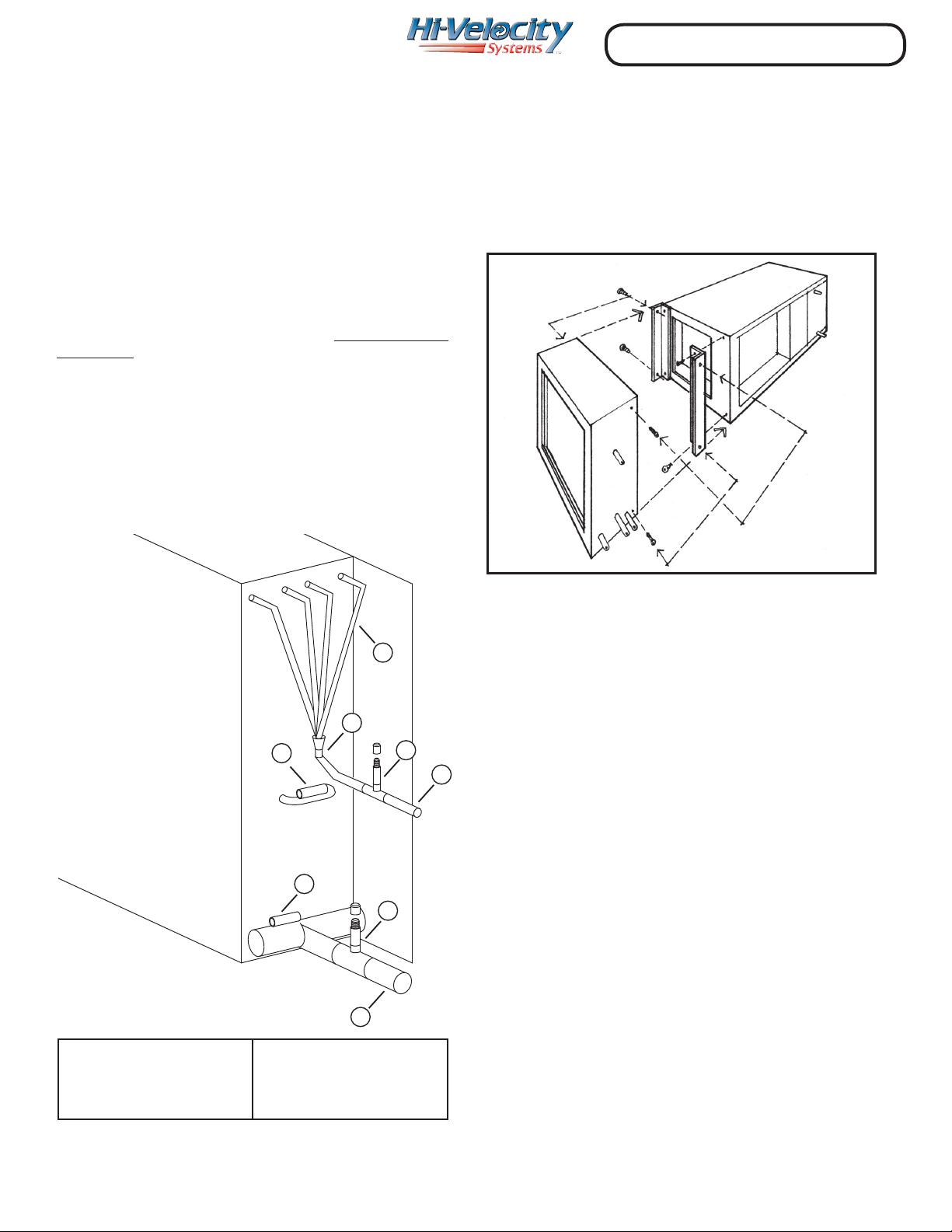
Mounting Brackets
Mounting the cooling coil to the fan coil can be done with
the L brackets supplied (Fig. 02), ensure that no screws puncture
the drain pan or coil. Page 8 has the dimensions of the cooling
modules.
Fig. 02 - Mounting brackets
Fig. 01 - Coil Assembly
1) Liquid line
2) High side access port
3) Refrigerant distributor
4) Distributor tubes
4
3
7
7
5) Suction line
6) Low side access port
7) Suction line temperature port
8) Middle coil temperature port
2
6
5
Access Ports
When refrigerant lines are connected to the RCM-I coil, high
and low side access ports must be connected as well. (Fig. 01 reference 2 & 6) With the use of a tee and reducer this process is
simplied. The access ports are required for system startup and
for future trouble shooting or service. When reading refrigerant
pressures/temperatures, always read them at the evaporator
1
access ports.
Note: 7 & 8 coil temperature ports are explained in Module HVS - Heat Pump Manual
Module RCM-I - RCM-I Coil Installation (2/8)
www.hi-velocity.com
Module RCM-I
RCM-I Installation
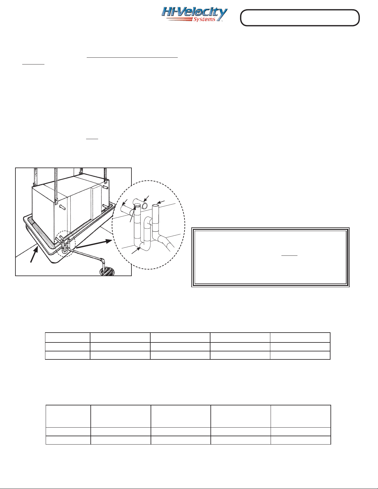
P - Trap
The condensate drain must have a minimum 3” P-Trap
installed (Fig. 03), and run at a slope of ¼” per foot in the
direction of the drain. All RCM-I modules come with a ¾” male
CPVC primary outlet and a ¾” secondary outlet. When installing
the P-Trap it must be installed on the primary outlet. It is good
practice to install a tee and a cap right above the P-Trap to act as
a clean out, in the event of the drain line being plugged. If a vent
is to be installed, it must be on the drain side of the P-Trap, and
must comply with all local building code requirements. If code
requires a secondary drain line, run the secondary line using the
same method. Otherwise, having it drain into a secondary drain
pan is acceptable. If the coil is located above a nished area,
a secondary drain pan must be installed. An equipment
stand/riser or rubber equipment mat may be necessary to
elevate the module o of the ground to allow for the P-Trap.
Secondary
Drain
Vent
Clean
Out
Primary
Drain
Pipe Sizing
Refer to charts below and Module HVS - Variable Speed Heat
Pump Manual for pipe sizing.
Piping the RCM-I
Only refrigerant grade pipe and ttings are to be used with
the RCM-I Module. Plumbing ttings may contain wax or other
contaminants which are detrimental to the proper operation of
the system. Insulate the suction line with a minumum of 3/8”
insulation. For inverter heat pump applications, insulating both
suction and liquid lines is mandatory. In high heat areas, a
minimum of 1/2” insulation may be needed. Support the pipe
every 5 feet, or whatever local code states.
Run the pipes in the most direct route possible, taking into
account structural integrity, building details and local building
codes. Minimum refrigerant pipe length is 16ft (6m). If going less
than 16 ft, coil the additional copper pipe up in horizontal loops
to ensure proper oil return. If the evaporator is located above
the condenser, slope any horizontal runs toward the condenser.
If the condenser is located above the evaporator, a P-trap must
be installed at the bottom of the vertical riser. For long vertical
risers, additional P-traps must be installed for every twenty feet.
Lines running over 213’ (65m) are not recommended.
Secondary Drain Pan
Table 02 - Minimum pipe sizes (up to 98’), factory charge and additional refrigerant required
P-Trap
Important: Return Air must be ltered
before entering the cooling module.
Fig. 03 - P-Trap, Secondary Drain Pan
Pipe Sizing
Table 01 - Minimum pipe sizes, maximum length and maximum lift
Model Liquid Line Suction Line Maximum Length Maximum Lift
HVS-36 3/8” (9.5 mm) 5/8” (15.9 mm) 213.25’ (65 m) 98.4’ (30 m)
HVS-60 3/8” (9.5 mm) 3/4” (19 mm) 213.25’ (65 m) 98.4’ (30 m)
The HVS Variable Speed Heat Pump comes with a factory charge. Additional charge will only be needed on line sets
longer than 49 ft. (See Table 02 below)
Add extra refrigerant
Model Liquid Line Suction Line Factory Charge (kg)
HVS-36 3/8” (9.5 mm) 5/8” (15.9 mm) 6.75 lbs (3.06 kg) 1 oz/ 3.3 ft
HVS-60 3/8” (9.5 mm) 3/4” (19 mm) 10.15 lbs (4.6 kg) 1 oz/ 3.3 ft
for line sets
over 49 ft (15 m)
Module RCM-I - RCM-I Coil Installation (3/8)
 Loading...